Thingiverse
CR10 All-In-One by Jan_P
by Thingiverse
Last crawled date: 3 years ago
UPDATE 21. Sep 2018
I love how this is turning into a team effort.
Janis Rocans was so kind as to share his update to the electronics cover that fit the newer boards for the 10S. He also included a picture and the actual Fusion file as well.
He also has a very interesting case/stand for a raspberry PI with 5 inch touch screen. Check it out here
UPDATE 16. Sep 2018
Many thanks to Scott Lahteine for remixing and sharing parts to support the 10S display. Check out his other models here.
Scott has some really interesting designs, and great updates to both the Creality and Prusa I3 printers.
NOTE It's been reported that my design may not fit newer CR10 control boards and displayes, but is reported to work with CR10 mini.
See comments for feedback.
To that end, I've added the Fusion360 design files, so that you can update and modify the design to fit your specific CR10 model.
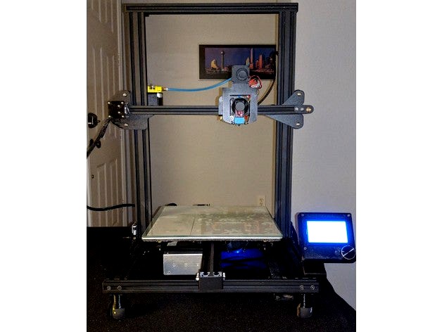
Inspired by https://www.thingiverse.com/thing:2747280, I set out to make my own version of integrating the control box electronics and power supply.
This kit includes:
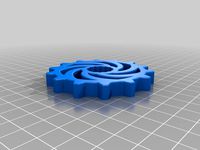
remodeled feet with integrated power connector and mount for squash ball for vibration dampening
mounting plate for power supply and mosfet with cooling fan
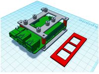
mounting plate for Melzi control board with integrated wire management and cooling fan
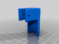
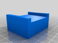
mount for navigator plugs from the stock wire harness
SD card slot moved to the front of the printer just below the control panel, and features a full size SD Card Reader, readily available from Amazon.
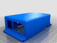
case and mount for the control display, and new display cable from Amazon
(update April 1, 2018)
Added STL for spool holder.
(update April 13, 2018)
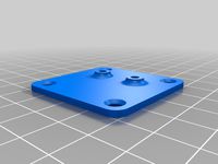
Adding cover plate for the remaining area of the printer, which includes:
a cover plate with integrated mount for power supply
a cover plate for mounting an Raspberry PI
blank cover plate to cover the remaining area
Total cost of conversion is about $20 plus filament.
Original wires are used except for wires from the switch and power receptacle to the power supply. The ribbon cable to the display was also replaced. I re-purposed the original connectors from the ribbon cable, simply transferred them over to a new and longer ribbon cable.
You may need to lengthen the wires to the fans as well.
The stock wire harness that originally connected the control box to the printer is unchanged. The extra length of some of the wires are managed by the integrated wire management loops below the Melzi board.
The Melzi board is raised off the mounting plate allowing routing of wires underneath the Melzi board. Making a cleaner looking implementation, and free airflow over the stepper drivers.
I designed the cover plates to primary use M3 hardware for mounting the boards, and M5 for mounting the plates to the extrusion.
M3 x 8 for the mosfet
M3 x 12 for the control board
M3 x 10 for the raspberry PI (yes, I enlarged the M2.5 holes in Raspberry PI to M3)
M5 x 10 for mounting the cover plates to the extrusion
The end product is a nice, clean looking, and fully integrated printer. Gone is the umbilical cord, and the clunky control box.
This change could expose live mains voltage wires and terminals.
While the leg with integrated power connections have some shielding, it will not prevent users from reaching and touching wire terminals.
Should someone reach underneath the printer, it is conceivable that they could access live mains voltage terminals.
It is recommended to take additional safety measures.
I love how this is turning into a team effort.
Janis Rocans was so kind as to share his update to the electronics cover that fit the newer boards for the 10S. He also included a picture and the actual Fusion file as well.
He also has a very interesting case/stand for a raspberry PI with 5 inch touch screen. Check it out here
UPDATE 16. Sep 2018
Many thanks to Scott Lahteine for remixing and sharing parts to support the 10S display. Check out his other models here.
Scott has some really interesting designs, and great updates to both the Creality and Prusa I3 printers.
NOTE It's been reported that my design may not fit newer CR10 control boards and displayes, but is reported to work with CR10 mini.
See comments for feedback.
To that end, I've added the Fusion360 design files, so that you can update and modify the design to fit your specific CR10 model.
Inspired by https://www.thingiverse.com/thing:2747280, I set out to make my own version of integrating the control box electronics and power supply.
This kit includes:
remodeled feet with integrated power connector and mount for squash ball for vibration dampening
mounting plate for power supply and mosfet with cooling fan
mounting plate for Melzi control board with integrated wire management and cooling fan
mount for navigator plugs from the stock wire harness
SD card slot moved to the front of the printer just below the control panel, and features a full size SD Card Reader, readily available from Amazon.
case and mount for the control display, and new display cable from Amazon
(update April 1, 2018)
Added STL for spool holder.
(update April 13, 2018)
Adding cover plate for the remaining area of the printer, which includes:
a cover plate with integrated mount for power supply
a cover plate for mounting an Raspberry PI
blank cover plate to cover the remaining area
Total cost of conversion is about $20 plus filament.
Original wires are used except for wires from the switch and power receptacle to the power supply. The ribbon cable to the display was also replaced. I re-purposed the original connectors from the ribbon cable, simply transferred them over to a new and longer ribbon cable.
You may need to lengthen the wires to the fans as well.
The stock wire harness that originally connected the control box to the printer is unchanged. The extra length of some of the wires are managed by the integrated wire management loops below the Melzi board.
The Melzi board is raised off the mounting plate allowing routing of wires underneath the Melzi board. Making a cleaner looking implementation, and free airflow over the stepper drivers.
I designed the cover plates to primary use M3 hardware for mounting the boards, and M5 for mounting the plates to the extrusion.
M3 x 8 for the mosfet
M3 x 12 for the control board
M3 x 10 for the raspberry PI (yes, I enlarged the M2.5 holes in Raspberry PI to M3)
M5 x 10 for mounting the cover plates to the extrusion
The end product is a nice, clean looking, and fully integrated printer. Gone is the umbilical cord, and the clunky control box.
This change could expose live mains voltage wires and terminals.
While the leg with integrated power connections have some shielding, it will not prevent users from reaching and touching wire terminals.
Should someone reach underneath the printer, it is conceivable that they could access live mains voltage terminals.
It is recommended to take additional safety measures.
Similar models
thingiverse
free

Raspberry Pi CR10 V3 Mount by randomdude
...hingiverse
this is a raspberry pi 3 mount for attaching to the power supply of a creality cr-10 v3. attaches with two m3 bolts.
thingiverse
free

K8400 VERTEX Upgrade With Raspberry Pi and Fish Eye Camera by Bo_Ris
...u will need two m5x30mm screws.
update 2-feb-2017: added video streaming script. the description is on the bottom of this page.
thingiverse
free
CR-10 Raspberry Pi Integration by michaeldeberry
...haust fan to mount everything as they were the perfect length. to mount the new fan i used some m3x12mm screws that i had around.
thingiverse
free

Crealtiy CR-10 Raspberry Pi Tray With RAMPS to Replace Power Supply!
...reality case and uses m4 captive nuts. the sections and boards mount with m3 sized self threading screws. i use these.
thank you!
thingiverse
free
CR10V2 Pi Cam Mount by JarneMeylemans007
...erry pi camera mount for cr10 v2 3d printer
it mounts on the rods from the cr10 v2
its designed with a m3 hole for a nut and bold
thingiverse
free

Rapsberry Pi mount for Prusa i3 6mm Aluminium plate version by markbenson
...h a raspberry pi and octoprint and a suitable 5v power supply. i added an l78s05cv 2a 5v fixed regulator to the ramps 12v supply.
thingiverse
free

CR10S Mod Standalone Melzi Board V2.0 by kervehrt
... mounts to support creality board v2.0 which comes with stock cr10s. also adapted the slot for the dual cable to the display ...
thingiverse
free

NZXT H1 Power Supply 3.5 Inch Pi Display Cover by rashbalash
...h pi display cover by rashbalash
thingiverse
just my design of an nzxt h1 power supply cover for a 3.5 inch raspberry pi display
thingiverse
free
Raspberry Pi Cover for RPI DSI Touchscreen by prushik
... most of the wires. it also allows usb, ethernet, audio, and power to be connected.
it's not perfect, but good enough for me.
thingiverse
free

Case for Raspberry Pi with 4-Relay Board ks0212 by hdiessner
...s://astrohd.de
update: july, 5th 2018: added a tray for geeetech i3 / prusa to mount the case atop an i3 printer without screws.
Cr10
3d_export
$21

Hall tree and Clothing Rack CR10
... real object. 3. lights and cameras are included in the scenes renders using vray * renders are made in 3ds max 2018 using vray 5
thingiverse
free

Clips for Ender 3, CR10, CR10S
.... maybe others, but only been tested with these.
these clips makes a tight fit, so that the cable and bowden tube stays in place.
thingiverse
free
X-axis endstop offset for cr10 cr10s Ender 3
...x-axis endstop offset for cr10 cr10s ender 3
thingiverse
x-axis endstop offset for cr10 cr10s ender 3
thingiverse
free

Filament Sensor CR10
...or cr10
thingiverse
remix of the sensor with fixation in order to face directly the extruder and ptfe tube
cr10, cr10s ender3...
thingiverse
free

Fan V4 CR10/CR10S Ender3 Versione 4 by creativesolutions-lab
...fan v4 cr10/cr10s ender3 versione 4 by creativesolutions-lab
thingiverse
fan v4 cr10/cr10s versione 4
thingiverse
free
CR10 Feet by Leighton417
...cr10 feet by leighton417
thingiverse
this is a cr10 feet for people who have short table width.
thingiverse
free

Dremel Attachment for CR10, Ender 3, Cr10s by Conn22_43
...verse
a bracket to hold a dremel onto any ender 3, cr10 bracket. i printed it in petg, but it can be made in any rigid material.
thingiverse
free

CR10S-Plus Hotend by scorpio_man30ro
...cr10s-plus hotend by scorpio_man30ro
thingiverse
cr10s-plus hotend
thingiverse
free
Leveling knob CR10 by JMJacques
...leveling knob cr10 by jmjacques
thingiverse
leveling knob cr10
thingiverse
free

Soporte Superior sensor filamento CR10 v2 - CR10 v3 by Guimir
...3 by guimir
thingiverse
soporte sensor de filamento guia superiror tipo cr10 v3 para convertir la cr10 v2 en extrusión directa.
Jan
turbosquid
$40

jan
... available on turbo squid, the world's leading provider of digital 3d models for visualization, films, television, and games.
3ddd
$1

Milano Bedding Jan
...диван , milano bedding , jan
milano bedding jan
design_connected
$29
Jan 350
...jan 350
designconnected
linteloo jan 350 computer generated 3d model. designed by navone, paola.
turbosquid
$9

Jan Robot
...rbosquid
royalty free 3d model jan robot for download as max on turbosquid: 3d models for games, architecture, videos. (1280124)
3d_export
$6

In-Jan 3D Model
...el
3dexport
in-jan logo ring pendent
in-jan 3d model download .c4d .max .obj .fbx .ma .lwo .3ds .3dm .stl dekasin 108971 3dexport
3ddd
$1

Jan Showers - Sarah
...jan showers - sarah
3ddd
скамья
модель скамейки jan showers - sarah bench no 415
мультисаб-материал, fbx + obj + 3ds
3d_export
$100

Jan 3D Model
...people human character teeth sexy sex jeans t-shirt shirt suit pant underware dress realistic
jan 3d model mrpanda 77564 3dexport
3d_export
$45

Jan 3D Model
...export
asian woman girl nude female character beauty angel realistic lowpoly low poly textures 3d
jan 3d model bzq 11388 3dexport
turbosquid
$25

Art jan design
... available on turbo squid, the world's leading provider of digital 3d models for visualization, films, television, and games.
3d_export
$32

etcetera low chair by jan ekselius
...etcetera low chair by jan ekselius
3dexport
etcetera low chair by jan ekselius
P
turbosquid
$9
Z i p p o
...lty free 3d model z i p p o for download as max, fbx, and obj on turbosquid: 3d models for games, architecture, videos. (1607301)
3ddd
$1
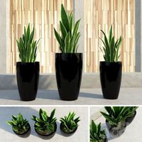
Triple P!
...iple p!
3ddd
горшок , цветок , листья
triple p!
3ddd
free
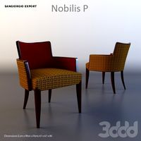
Nobilis P
... sangiorgio export
nobilis phttp://www.sangiorgioexport.com/nobilis.html#p
san giorgio export
design_connected
$16
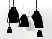
Caravaggio P
...caravaggio p
designconnected
lightyears caravaggio p computer generated 3d model. designed by manz , cecilie .
design_connected
$16
Lady P
...lady p
designconnected
origlia lady p computer generated 3d model. designed by origlia, sviluppo.
design_connected
$16
Anfora P
...anfora p
designconnected
lzf anfora p computer generated 3d model. designed by herranz, miguel.
design_connected
$13
Tri-p
...tri-p
designconnected
foscarini tri-p computer generated 3d model. designed by diesel creative team.
turbosquid
$8
Z i p p o Lighter
... 3d model z i p p o lighter for download as max, fbx, and obj on turbosquid: 3d models for games, architecture, videos. (1617079)
3ddd
$1
Carlesso Pliet P
...carlesso pliet p
3ddd
carlesso , pliet p
carlesso pliet p
design_connected
$9
LC11-P
...lc11-p
designconnected
cassina lc11-p dining tables computer generated 3d model. designed by le corbusier.
One
turbosquid
$2
one plus one
... available on turbo squid, the world's leading provider of digital 3d models for visualization, films, television, and games.
3ddd
$1
One
...one
3ddd
стул
офисный стул one
3ddd
free

one
...
palazetti one ,http://palazzetti.ca/index.php/component/virtuemart/seating/armchairs-lounges/one-chair-detail?itemid=0
turbosquid
$35

One A
... available on turbo squid, the world's leading provider of digital 3d models for visualization, films, television, and games.
turbosquid
free
One
... available on turbo squid, the world's leading provider of digital 3d models for visualization, films, television, and games.
3ddd
$1
Стул One
...стул one
3ddd
one , magis
кресло magis s.p.a , one
3ddd
$1
Стул One
...стул one
3ddd
one , magis
кресло one chair (4star), magis s.p.a.
3d_export
$20

xbox one
...xbox one
3dexport
xbox one
3ddd
$1

xbox one
... консоль , джойстик
xbox one + kinect + gamepad
3ddd
free
One
...nstantin grcic
артикул ct-284 (cosmorelax.ru)
размер l36xw41xh82.5, sh 77cm
цвет черный, красный
материал алюминий
вес 2,5 кг
All
turbosquid
$20

all
... available on turbo squid, the world's leading provider of digital 3d models for visualization, films, television, and games.
turbosquid
$5
all
... available on turbo squid, the world's leading provider of digital 3d models for visualization, films, television, and games.
design_connected
$29

All-Two
...all-two
designconnected
bonaldo all-two computer generated 3d model. designed by bicego, sergio.
design_connected
$29

All-One
...all-one
designconnected
bonaldo all-one computer generated 3d model. designed by bicego, sergio.
design_connected
$16

Holly All
...holly all
designconnected
serralunga holly all computer generated 3d model. designed by starck, philippe.
3d_export
$15

all terrain
...all terrain
3dexport
turbosquid
$29

Holly All
... available on turbo squid, the world's leading provider of digital 3d models for visualization, films, television, and games.
turbosquid
$19
Fireplace (All)
... available on turbo squid, the world's leading provider of digital 3d models for visualization, films, television, and games.
turbosquid
$19

Fireplace (All)
... available on turbo squid, the world's leading provider of digital 3d models for visualization, films, television, and games.
turbosquid
$19

Fireplace (All)
... available on turbo squid, the world's leading provider of digital 3d models for visualization, films, television, and games.