Thingiverse
CR-10 Dual Z with top mounted stepper by StvPtrsn
by Thingiverse
Last crawled date: 3 years, 1 month ago
Last Fall I purchased and installed the dual Z upgrade for my regular CR-10. For weeks I fought bed leveling with the steppers going out of alignment for whatever reason. Drawing inspiration from Caster's Youtube video (thing 2569379) I set out to design my own belt driven dual Z setup. I completed it and published it as thing 2628377. Having used it for the past 4+ months I have to say this is the best modification I've done to my CR-10. Where I used to re-level the bed after almost every print, now I only do it when I change build surfaces.
One of the problems with the previous design was that it over constrained the left side lead screw. I spent a lot of time with a set of calipers and a straight edge making sure the z stepper and the upper bearing mounts were lined up perfectly with the lead screw nut so this wouldn't actually cause print problems.
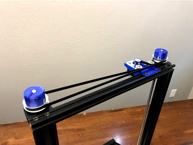
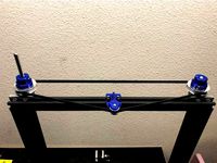
My new design is an attempt to resolve that problem. With this setup the Z stepper is relocated to the top of the frame and the lead screws are allowed to float at the bottom. As before I do not like driving set screws into the threads of the lead screws so I spent the effort designing alternative ways to attach the pulleys :)
I secured the wiring extension with 1" lengths cut from the extrusion inserts that came with the printer. If you split them down the back side they will wrap around the wiring and allow you to secure it in the frame slots. There is plenty of room to run this down the right extrusion and the X carriage bracket clears it without problem.
Parts list (for CR-10S):
BIQU GT2 Synchronous Wheel 60 Teeth 8mm Bore Aluminum Timing Pulley for 3D Printer 6mm Width Belt (Pack of 2pcs)
Link: http://a.co/eORAb49
BIQU GT2 5mm Bore Aluminum Toothless Timing Belt Idler Pulley for 3D Printer 6mm Width Timing Belt (Pack of 5pcs)
Link: http://a.co/2LMLfJs
BEMONOC Pack of 2pcs GT2 Driver Belt 900-2GT-6 Timing Belt in Closed Loop Rubber L=900mm W=6mm 450 Teeth
Link: http://a.co/1px2mDt
Qunqi 5PCS Aluminum GT2 Timing Belt Pulley 20 Teeth Bore 5mm Width 6mm and Wrench for RepRap 3D Printer Prusa i3
Link: http://a.co/hLGLZjm
20-Pack 608 ZZ Ball Bearings , 608zz Metal Double Shielded Miniature Deep Groove Skateboard Ball Bearings (8mm x 22mm x 7mm)
Link: http://a.co/6dibLpCAny 608 bearing should work since we are not putting a heavy axial load on these. The ones linked above specify "deep groove", I'm not sure if all 608s have the same groove or not. The bearings I used I bought for fidget spinners and did not specify they were deep groove.
You'll also need some way to extend the stepper wiring. I have a CR-10 harness extension kit so I just used the Z wire out of that.
*in addition to these parts a standard CR-10 will require a second lead screw and right side bracket. Since I bought the dual Z upgrade I have not needed to model the right side bracket.
Hardware:
(2) M5x20 screws for the stepper mount idlers. Just thread them into the plastic.
(2) M5 washers for under the stepper idlers to keep them from rubbing on the mount
(4) M5x8 screws with t-nuts to attach the stepper mount to the frame
(4) M4x20 screws with t-nuts for mounting the bearing brackets to the frame
(4) M4x6 button head cap screws with the head filed down to about 6.5mm diameter (chuck it up in a drill and run it over a file) These are only if you are using the 60T pulley adapters provided. Alternatively just use the set screws.
(4) M3 locknuts for Below_Bearing_Clamp_x2 and 8mm_60T_GT2_Clamp_x2
(4) M3x10 for Z_Bearing_Mount_x2. They screw into the sides to lock the bearing in place.
(4) M3x10 to attach the stepper motor
(4) M3 washers for the stepper motor screws
(2) M3x12 for Below_Bearing_Clamp_x2
(2) M3x20 for 8mm_60T_GT2_Clamp_x2
Firmware changes are required. You can do this at least two ways.
Edit Marlin 1.1.8 line 532
define DEFAULT_AXIS_STEPS_PER_UNIT { 80, 80, 400, 101 }
Change the 400 to 1200
or
From a terminal send commands:
M92 Z1200 to set the Z steps/mm then M500 to save the setting
Note: You will likely lose some Z height with this modification depending on how your x carriage wiring is set up.
Please let me know if you build this. I'd like to hear how it works out.
One of the problems with the previous design was that it over constrained the left side lead screw. I spent a lot of time with a set of calipers and a straight edge making sure the z stepper and the upper bearing mounts were lined up perfectly with the lead screw nut so this wouldn't actually cause print problems.
My new design is an attempt to resolve that problem. With this setup the Z stepper is relocated to the top of the frame and the lead screws are allowed to float at the bottom. As before I do not like driving set screws into the threads of the lead screws so I spent the effort designing alternative ways to attach the pulleys :)
I secured the wiring extension with 1" lengths cut from the extrusion inserts that came with the printer. If you split them down the back side they will wrap around the wiring and allow you to secure it in the frame slots. There is plenty of room to run this down the right extrusion and the X carriage bracket clears it without problem.
Parts list (for CR-10S):
BIQU GT2 Synchronous Wheel 60 Teeth 8mm Bore Aluminum Timing Pulley for 3D Printer 6mm Width Belt (Pack of 2pcs)
Link: http://a.co/eORAb49
BIQU GT2 5mm Bore Aluminum Toothless Timing Belt Idler Pulley for 3D Printer 6mm Width Timing Belt (Pack of 5pcs)
Link: http://a.co/2LMLfJs
BEMONOC Pack of 2pcs GT2 Driver Belt 900-2GT-6 Timing Belt in Closed Loop Rubber L=900mm W=6mm 450 Teeth
Link: http://a.co/1px2mDt
Qunqi 5PCS Aluminum GT2 Timing Belt Pulley 20 Teeth Bore 5mm Width 6mm and Wrench for RepRap 3D Printer Prusa i3
Link: http://a.co/hLGLZjm
20-Pack 608 ZZ Ball Bearings , 608zz Metal Double Shielded Miniature Deep Groove Skateboard Ball Bearings (8mm x 22mm x 7mm)
Link: http://a.co/6dibLpCAny 608 bearing should work since we are not putting a heavy axial load on these. The ones linked above specify "deep groove", I'm not sure if all 608s have the same groove or not. The bearings I used I bought for fidget spinners and did not specify they were deep groove.
You'll also need some way to extend the stepper wiring. I have a CR-10 harness extension kit so I just used the Z wire out of that.
*in addition to these parts a standard CR-10 will require a second lead screw and right side bracket. Since I bought the dual Z upgrade I have not needed to model the right side bracket.
Hardware:
(2) M5x20 screws for the stepper mount idlers. Just thread them into the plastic.
(2) M5 washers for under the stepper idlers to keep them from rubbing on the mount
(4) M5x8 screws with t-nuts to attach the stepper mount to the frame
(4) M4x20 screws with t-nuts for mounting the bearing brackets to the frame
(4) M4x6 button head cap screws with the head filed down to about 6.5mm diameter (chuck it up in a drill and run it over a file) These are only if you are using the 60T pulley adapters provided. Alternatively just use the set screws.
(4) M3 locknuts for Below_Bearing_Clamp_x2 and 8mm_60T_GT2_Clamp_x2
(4) M3x10 for Z_Bearing_Mount_x2. They screw into the sides to lock the bearing in place.
(4) M3x10 to attach the stepper motor
(4) M3 washers for the stepper motor screws
(2) M3x12 for Below_Bearing_Clamp_x2
(2) M3x20 for 8mm_60T_GT2_Clamp_x2
Firmware changes are required. You can do this at least two ways.
Edit Marlin 1.1.8 line 532
define DEFAULT_AXIS_STEPS_PER_UNIT { 80, 80, 400, 101 }
Change the 400 to 1200
or
From a terminal send commands:
M92 Z1200 to set the Z steps/mm then M500 to save the setting
Note: You will likely lose some Z height with this modification depending on how your x carriage wiring is set up.
Please let me know if you build this. I'd like to hear how it works out.
Similar models
thingiverse
free
CR-10 Dual Z Pulley Setup by StvPtrsn
...uxcell a16031400ux0530 3d printer 2gt-6 ring closure timing belt closed 852mm circumference, hss
uxcell
link: http://a.co/bhjz4wh
thingiverse
free

GT2 idler for 608 bearing M3 NEMA 17 stepper
...
idler for 6mm gt2 belt, designed to mount onto a nema 17 stepper motor and leave room for a 16 tooth pulley
step files included
thingiverse
free

Idler pulley for 6mm GT2 timing belt with one 624ZZ ball bearing by hlavaatch
...iverse
idler pulley for a 6mm gt2 timing belt.
comes with two spacers for 10mm wide mount slot to keep the pulley in the middle.
thingiverse
free
CR-10s Pro Z Belt Tensioner
...for the belt sync or an actual idler of similar size. on tinkercad: z belt tensioner updated with yet...
thingiverse
free

TRONXY X5S - Z motor sync by WT1704
...e platform on the stepper and 3 * m5 screws and nuts for the pulley
1 * m3 screw and nut to hold the tension stick with the block
thingiverse
free

Belt driven Z pulley mount w/ GT2 6mm belt 5mm bore 20t idler by Evilkoal
...e idler mount to fit the idlers i have.
gt2 20t 6mm belt, 5mm bore idler.
printed with 50% "archimedian chords" infill.
thingiverse
free

GT2 2mm Idler Pully by Timelord83
...gt2 2mm idler pully by timelord83
thingiverse
40 tooth idler 608 pulley for gt2 2mm x 6mm wide gt2 belts
grabcad
free

GT2-6mm Pulleys and Idlers
...gt2-6mm pulleys and idlers
grabcad
some of the most used pulleys and idlers for gt2-6mm timing belts.
created with freecad 0.18
thingiverse
free
Internal NEMA17 Timing Belt reduction by gouldpa
...
2xhttps://3dprintingperth.com/collections/stepper-motors/products/20-teeth-6mm-width-3mm-inner-18mm-outer-gt2-idler-pulley-wheel
thingiverse
free

Idler 6mm GT2 6mm timing belt by Vandalisimo
....alicdn.com/kf/htb1mtv5ipxxxxalxfxxq6xxfxxx2/hot-10pcs-lot-624zz-ball-bearing-4-13-5-mm-chrome-steel-bearing-deep-groove-ball.jpg
Stvptrsn
thingiverse
free
Bin Dividers for Harbor Freight 40 Bin Organizer by StvPtrsn
... let me know if you make this and find it useful.
update: i ended up needing 4 and 5 compartment bin inserts so i uploaded them.
thingiverse
free

MMU2 Amazon "Festo" Holder by StvPtrsn
...r in or it will not snap onto the spool holder stand. step file included. original fusion360 file included in the source thing.
thingiverse
free

OpenRC F1 2017 Update - 1pc Chassis, Dual Ext Lid by StvPtrsn
...e 300x300mm cr-10 build plate.
second i spliced the 2017 updated lid onto the dual extrusion original lid to accommodate the fin.
thingiverse
free

CR-10 30mm Spool Holder by StvPtrsn
...rger than stock diameter nut. it fits nicely behind the spool holder bracket so it doesn't need to be held while tightening.
thingiverse
free

Prusa MK3 Spool Holder for 30mm Spools by StvPtrsn
... maximum 95mm width.
update:
uploaded step files and added a shorter version of the mount for narrower spools (up to 70mm width).
thingiverse
free

Sterilite 20qt Filament Storage System by StvPtrsn
...uwpnbb
1x new and improved eva-dry e-333 renewable mini dehumidifier
by eva-dry
link: http://a.co/fqjpxtf
4x lengths of ptfe tube
thingiverse
free

Bin Dividers for Akro-Mils Small Parts Organizers by StvPtrsn
...and/or remix.
if you have a specific divider configuration request leave it in the comments. it doesn't take long to create.
thingiverse
free
CR-10 Dual Z Pulley Setup by StvPtrsn
...uxcell a16031400ux0530 3d printer 2gt-6 ring closure timing belt closed 852mm circumference, hss
uxcell
link: http://a.co/bhjz4wh
thingiverse
free

Folgertech FT-5 R2 Assembly Aids by StvPtrsn
...ossbars made it much easier than using the spool holder as a spacer. the stl should be both parts in one so just print one pair.
thingiverse
free

Hypercube Evolution, My Parts and Remixes - No inserts by StvPtrsn
...d models. they are not exact duplicates (though the y carriage is close to exact), i made changes where i thought it made sense.
Cr
turbosquid
$15
Creazioni CR-673 CR-4461
... available on turbo squid, the world's leading provider of digital 3d models for visualization, films, television, and games.
3ddd
$1
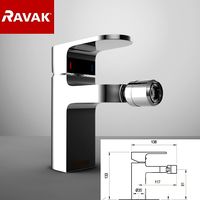
Ravak CR 055.00
...ravak cr 055.00
3ddd
ravak , смеситель
ravak cr 055.00
turbosquid
$100

CR-002
...
turbosquid
royalty free 3d model cr-002 for download as stl on turbosquid: 3d models for games, architecture, videos. (1686037)
3ddd
$1

Ravak CR 012.00
...ravak cr 012.00
3ddd
ravak , смеситель
смеситель ravak cr 012.00
3ddd
free
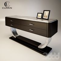
Консоль CR Currin
...ь , cr currin
консоль cr currin
ширина - 1675 мм
глубина - 510 мм
общая высота - 810 мм
3ddd
$1
CR 39444
...0
диаметр: 100
тип патрона: gu5,3 gu10
количество ламп: 1
мощность: 35w
цвет: золото хрусталь
материал: металл хрусталь exclusive
3d_ocean
$89

Honda CR-Z
...www.youtube.com/watch?v=rrbb4d4lypk ` he honda cr-z‘s exterior styling is formed around a “one-motion wedge” concept with a lo...
3ddd
$1

Creazoni / STEFY CR-8901
...creazoni / stefy cr-8901
3ddd
creazoni
creazioni stefy cr-8901
turbosquid
$60

Chain-CR-001
...squid
royalty free 3d model chain-cr-001 for download as stl on turbosquid: 3d models for games, architecture, videos. (1680536)
turbosquid
$99

Honda CR-Z
... available on turbo squid, the world's leading provider of digital 3d models for visualization, films, television, and games.
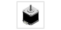
Stepper
turbosquid
$85

Stepper
... available on turbo squid, the world's leading provider of digital 3d models for visualization, films, television, and games.
3d_ocean
$22
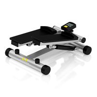
Mini Stepper
...gymnastic indoor legs machine mini silver sport stepper trainer workout
3d model of silver and black mini stepper with a counter.
turbosquid
$3

stepper deluxe
...osquid
royalty free 3d model stepper deluxe for download as on turbosquid: 3d models for games, architecture, videos. (1284335)
turbosquid
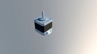
$49
Stepper Motor
... available on turbo squid, the world's leading provider of digital 3d models for visualization, films, television, and games.
turbosquid
$5
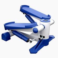
Fitness Stepper
... available on turbo squid, the world's leading provider of digital 3d models for visualization, films, television, and games.
turbosquid
$1

stepper motor driver
...stepper motor driver for download as , fbx, dae, obj, and stl on turbosquid: 3d models for games, architecture, videos. (1688860)
turbosquid
$1

Stepper motor driver
... model stepper motor driver for download as obj, stl, and ige on turbosquid: 3d models for games, architecture, videos. (1577811)
3d_export
$5
Stepper motor Nema17 17HS4401
...stepper motor nema17 17hs4401
3dexport
turbosquid
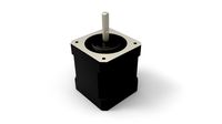
$1
Nema 17 Stepper motor
... available on turbo squid, the world's leading provider of digital 3d models for visualization, films, television, and games.
turbosquid
$1
Nema 17 Stepper Motor 59Nm
... available on turbo squid, the world's leading provider of digital 3d models for visualization, films, television, and games.
Dual
turbosquid
free

Dual Pistols
...ls
turbosquid
free 3d model dual pistols for download as fbx on turbosquid: 3d models for games, architecture, videos. (1320360)
turbosquid
$2
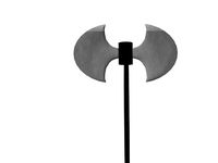
Dual Axe
...urbosquid
royalty free 3d model dual axe for download as fbx on turbosquid: 3d models for games, architecture, videos. (1332372)
turbosquid
$10
Dual Lesaths
... available on turbo squid, the world's leading provider of digital 3d models for visualization, films, television, and games.
3ddd
$1
плитка Dual Bianco (Испания)
...й плитки venis dual (испания). технические качества: устойчивость к стирания, отличная геометрия, отсутствие проблем при укладке.
turbosquid
$35

Dual Mesh Fonts
...ree 3d model dual mesh fonts for download as ma, obj, and fbx on turbosquid: 3d models for games, architecture, videos. (1352989)
turbosquid
$29

Dual Flask with Bungs
...del dual flask with bungs for download as obj, fbx, and blend on turbosquid: 3d models for games, architecture, videos. (1210512)
turbosquid
$19
Dual Socket Plug
...3d model dual socket plug for download as obj, fbx, and blend on turbosquid: 3d models for games, architecture, videos. (1303912)
turbosquid
$13
Dual Adjustable Pulley
... available on turbo squid, the world's leading provider of digital 3d models for visualization, films, television, and games.
turbosquid
$10

Amoi N809 Dual
... available on turbo squid, the world's leading provider of digital 3d models for visualization, films, television, and games.
turbosquid
$5
Dual Turret Tank
... available on turbo squid, the world's leading provider of digital 3d models for visualization, films, television, and games.
Z
3d_export
$5
nissan z
...nissan z
3dexport
nissan z
3ddd
$1

Vase Z
...vase z
3ddd
vase z
3ddd
$1
полотенцесушить Z
...полотенцесушить z
3ddd
полотенцесушитель
полотенцесушить z
design_connected
free
Z-Chair
...z-chair
designconnected
free 3d model of z-chair designed by karman, aleksei.
design_connected
$11

Z Lamp
...z lamp
designconnected
phillips z lamp computer generated 3d model. designed by kalff, louis.
3d_export
$5
Dragon balls z
...dragon balls z
3dexport
dragon ball z
turbosquid
$20

Fighter Z
...
turbosquid
royalty free 3d model fighter z for download as on turbosquid: 3d models for games, architecture, videos. (1292563)
turbosquid
$9

Pen Z
...pen z
turbosquid
free 3d model pen z for download as obj on turbosquid: 3d models for games, architecture, videos. (1686775)
turbosquid
free
z chair
...z chair
turbosquid
free 3d model z chair for download as max on turbosquid: 3d models for games, architecture, videos. (1410230)
turbosquid
$5

Letter Z
...urbosquid
royalty free 3d model letter z for download as max on turbosquid: 3d models for games, architecture, videos. (1408540)
10
turbosquid
$25

10
... available on turbo squid, the world's leading provider of digital 3d models for visualization, films, television, and games.
turbosquid
$10
a-10
... available on turbo squid, the world's leading provider of digital 3d models for visualization, films, television, and games.
3ddd
$1

EX 10
...ex 10
3ddd
samsung , фотоаппарат
ex 10
3ddd
$1

Bed 10
...bed 10
3ddd
постельное белье
bed 10
evermotion
$25

Scene 10 Archinteriors vol. 10
...dering design interior
take a look at textured and shadered visualization scene ready to be rendered.. evermotion 3d models shop.
3ddd
$1

Curtains 10
...curtains 10
3ddd
curtains 10
3ds max 2011,fbx + textures
polys: 100355
3ddd
free

PLANTS 10
...plants 10
3ddd
цветок , горшок
plants 10,, with 3 different color planter boxes
turbosquid
$24

Chandelier MD 89310-10+10 Osgona
... chandelier md 89310-10+10 osgona for download as max and fbx on turbosquid: 3d models for games, architecture, videos. (1218762)
design_connected
$29
Nuvola 10
...nuvola 10
designconnected
gervasoni nuvola 10 computer generated 3d model. designed by navone, paola.
design_connected
$22

Kilt 10
...kilt 10
designconnected
zanotta kilt 10 computer generated 3d model. designed by progetti, emaf.
Top
archibase_planet
free
Top
...top
archibase planet
top
top - 3d model (*.gsm+*.3ds) for interior 3d visualization.
3ddd
free
Range Top V36C top
...range top v36c top
3ddd
гриль
проф. гриль range top v36c top
archibase_planet
free
Top
...top
archibase planet
dresser kitchen furniture
top - 3d model (*.gsm+*.3ds) for interior 3d visualization.
archibase_planet
free
Top
...top
archibase planet
bracket bar furniture
bar top - 3d model (*.gsm+*.3ds) for interior 3d visualization.
turbosquid
$5

Top
...lty free 3d model top for download as ma, max, blend, and obj on turbosquid: 3d models for games, architecture, videos. (1579951)
turbosquid
$39
Top
... available on turbo squid, the world's leading provider of digital 3d models for visualization, films, television, and games.
turbosquid
$30
Top
... available on turbo squid, the world's leading provider of digital 3d models for visualization, films, television, and games.
3d_export
$15

top knifle
...top knifle
3dexport
top knifle
design_connected
$11

Drop Top
...drop top
designconnected
plumen drop top computer generated 3d model.
3d_export
$245

top of the material
...top of the material
3dexport
top of the material,commercial ceiling ceiling material, metal material
Mounted
3d_export
free

mounting bracket
...mounting plate is the portion of a hinge that attaches to the wood. mounting plates can be used indoors, cabinetry and furniture.
turbosquid
$2

MOUNTING
... available on turbo squid, the world's leading provider of digital 3d models for visualization, films, television, and games.
turbosquid
free

Mounts
... available on turbo squid, the world's leading provider of digital 3d models for visualization, films, television, and games.
turbosquid
free

Mount Fuji
...fuji
turbosquid
free 3d model mount fuji for download as obj on turbosquid: 3d models for games, architecture, videos. (1579977)
3d_export
$5

Headphone mount LR
...headphone mount lr
3dexport
headphone mount l+r
turbosquid
$39

Mount rainier
...quid
royalty free 3d model mount rainier for download as fbx on turbosquid: 3d models for games, architecture, videos. (1492586)
turbosquid
$5

pipe mounting
...quid
royalty free 3d model pipe mounting for download as obj on turbosquid: 3d models for games, architecture, videos. (1293744)
turbosquid
$3

Mounting Tires
...uid
royalty free 3d model mounting tires for download as fbx on turbosquid: 3d models for games, architecture, videos. (1708511)
3d_export
$5

Magnetic GoPro Mount
...pro mount
3dexport
cool magnetic mount for gopro. allows you to mount the camera on flat metal surfaces and get exclusive shots.
turbosquid
$5

Stone Mount
...ty free 3d model stone mount for download as ma, obj, and fbx on turbosquid: 3d models for games, architecture, videos. (1370306)