Thingiverse
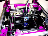
Corexy plasma cutter by Stoney
by Thingiverse
Last crawled date: 3 years ago
Firstly, feel free to advise or comment, this is my first XY build and first corexy.
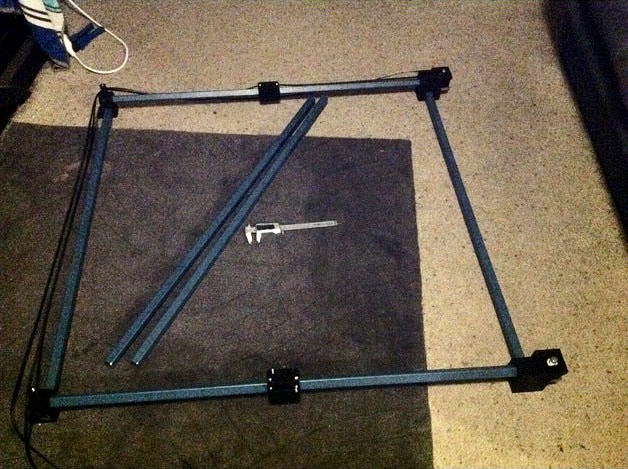
I bought a small plasma cutter (<8mm cut) last year and have found it quite useful, made myself stencils to cut things like stepper motor mounts etc but it needs to be CNC'ed, start price in stores is crazy (like $20,000) I am in australia and I decided I wanted a budget of $100 on top of motor and a controller, little more expensive to get parts and part of the idea was to see if I could make it with things I had in my top parts drawer, avoiding large bearings and carriages and rails etc. Also wanted it to be around 1metre a side so needed to be stiff.
I wanted motors and controller well away from plasma so I figured corexy was good for this as both motors are rear mounted and cables are short and can be inflexible and heavily shielded if required.
An easy steel to get is 20mm square tube with 1.6mm walls, bought a 6m length for $15 (cost $2.50 metre .. cut to 1m lengths if required).
The holes in the end_brace and ider_brace are 20.2mm on a side, I need to hammer the steel into place, it is quite stiff with my printer settings.
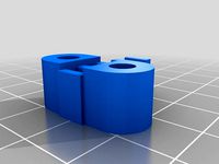
The 4 bearings in the Y carriages are the cheapest V groove (aliexpress "V624ZZ V624 624VV 4x13x6mm V Groove Carbon Steel Deep Groove Ball Bearing" <$7AU for 20.
change: added idler624zz part. These and the spacers are designed to printed at 0.3mm layer height, all vertical dimensions are integers of 0.3mm.
These are not internally flanged to retain bearing and the inner hole is 7mm but I found I needed to bash the bearings into place with a suitable socket, they are not falling out for me, ymmv, top is slightly tapered to assist seating.
You need 8 of the idler624zz part and probably 4 spacers (yet to be determined), I used 4x35mm socket head bolts with 2 nuts on each and since nearly 10mm was unthreaded made a spacer part 4x8.1_spacer that holds the idlers in the correct position, 2 of these assemblies screw into the 10mm deep holes in the front idler_brace part. total cost blew out here, 20x35mm, 20x30mm and 50 4mm nuts was $25, I am starting to see where that $20,000 pricetag for a commercial unit comes from.
(deleted: and the idler bearings are currently cheap 4x13x5 versions, hence flange parts to hold belt in place, will likely add some nice idlers here or maybe 3d print something suitable.)
So far the end_brace which holds the stepper motors is the only part that needs reversing and printed twice, it has blind ends, later realised that was limiting adjustability so designed the idler_brace part so both pieces of steel slide all the way through, I can drill a hole or several through the steel to retain the brace if a grub screw is insufficient.
The bearing runner has some springs to pull the slot closed and keep the little bearings on the corners, movement feels quite good with very little slop.
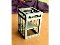
Full accuracy of a 3D printer etc is not required or stiffness since this thing can move at 5mm/sec max and it will do the job.
Plan is to make a wooden square frame to bolt the chassis too and then fit a steel mesh in place as a base, maybe add a water table underneath if required, this is for light use though so I will probably just keep an eye on it.
Runs a simple 2 axis grbl controller operated from a 20V tool battery, no mains connection, only connection to plasma cutter will be a relay across the trigger to fire the plasma. Project files stored on SD card. This is to reduce mains interference as much as possible.
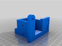
Added: y_idler_bracket, bolts to the top inside edge of the v_quad_bear_brace (photo attached) with 3x10-15mm bolts through the top and 4mmx10 through the side into the blank ends of the bearing holes. Holds the 2 X carriage beams and 2 idlers.
A single low one on diagonal corners and a single high one on the other corners, see the corexy_option_2 image, the numbers indicate the height of each pulley, the 2 top pulleys are on the same axle, this way there is no need to cross over the belts at any point.
For 1000mm end beams my X carriage beams needed to be cut to 965mm using 1000mm side lengths (X beams are shorter as belt runs past each end), total cutting area ended up at X:800mm. Y: 750mm.
I ended up doing a redesign of the idler_brace part and called it idler_brace_destrain after having one shatter trying to hammer it into position, the later version has 0.5mm gaps clamping the steel that can be tightened with a 3mm bolt if required, need to adjust the vertical side Y frame parts so you have exactly the same distance top and bottom obviously or the v_quad_bear_brace parts will not slide smoothly
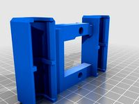
The x_carriage part, need 2 of these, they run on the 2 X beams and have 2 slots on each side to clamp the belt ends in place with 3mm bolts. Axles are 4x30mm or 35mm bolts from the sides for top bearings, 2 parts connect these together, tool_holder_minimum bolts above the 2 x carriage parts and x_carriage lower bolts underneath and holds the 4 lower bearings, 4x20mm bolts hold the lower on, 6x3mm bolts go through all 3 pieces for rigidity.
belt clamps bolt onto the sides of the X carriage parts and retain the belts, need 4 of these and 8 off M3x12.
Added a basic tool holder, really only a placer to bolt the 2 X carriage parts together at the moment
Fitted the electronics I bought months ago for this job, Mega2560, Ramps 1.4 and smart adapter (graphic LCD, encoder and SD card) some time ago, only the X and Y stepper drivers installed, removed D1 (as per ramps schematic https://reprap.org/mediawiki/images/3/3f/Arduinomegapololushieldschematic.png) so the 18-20V motor voltage is not zapping the arduino regulator, fitted a BMS set to 8.5V and feeding this to the cathode pin of D1 to supply the mega, fitted a lolin esp8266 board running esp-link to the serial and i now have wifi serial to the board, installed tcpserial so I can create a virtual serial port if required.
Firmware installed currently is repetier with homing switches disabled, I tried Marlin but its insistence on end stops is a buzz kill, I compiled repetier to allow both laser and CNC modes so I see which is best suited, I imagine laser mode should be fairly ideal for what I want to accomplish.
SD card reader works, so thats great. I wish there was a mega2560/smart adapter GRBL port but I am yet to find one.
Decided to add homing switches, since i had spares, seeing as I have a display and want to keep wires short then I will be using motors at the front of the machine, the switches are mounted on the angled part of the end_brace part, the x_switch_tag mounts on the bottom unused hole of the belt tensioner on the front left of carriage.
Total useable size now calibrated (200 steps/mm) is Y = 750mm and X = 800mm
added pen_holder for a whiteboard marker as used in second video, 16.5mm diameter.
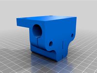
main_cable_egress bolts to one of the Y carriage top 2 bearing axle holes and lifts the plasma cable above the belts. The torch_clamp parts hold the handle of the plasma torch (22.8mm? I think diameter), I had some long 3/16 buttonhead bolts, the head of the bolt sits in the top portion of the torch_holder, the square nut presses into the x_carriage_lower and the torch_knob parts thread onto the top end of the bolt and are the fine height and angle adjustment for the plasma torch.
Couple of videos of testing.. (earlier X carriage design that was sloppier than the current version)
https://youtu.be/11hIlgczhxIhttps://youtu.be/BUYwdXEGoV0
Deleted all the rsdoc files and uploaded them all in one zip, this also has assembly models that do not have stl's. Added some screencaps as they may come in handy if anyone ever builds on :)
added electronics to trigger the plasma cutter, I used a TLP222G-2 opto mosfet with a series 2.2k resistor and 3mm LED, attached it to the heatbed mosfet output (D10) on the ramps board, I have not checked to see what the plasma needs to trigger yet but I expect the 1A capability and 3500V isolation should do the trick, also found a 2 pin DIN connector so I can plug the controller directly into the front of the plasma cutter instead of tampering with the trigger switch, saves running any wires from controller to cutting torch.
I left the wires to the ramps board short and long wires on the plasma side so any induced noise will be minimal, the plasma cutter already is designed to cope with it since it has a long trigger wire.
Attached photos of the air wired electronics and hot melt glued into the little case, front hole is for the indicator LED.
Attached a couple more photos of unit, and ramps_case dxf and gcode files, hopefully the first thing I will cut is a steel case for the ramps/arduino and breakout for the graphic LCD.
gcode was created by drawing a 2D image in designspark with inner elements in green and outer border in red, this determines the order they will be cut, import dxf into T2laser, making sure dxf option for sequential colour is enabled, export gcode .. then edit it to turn it from GRBL compatible to repetier firmware.
issues are that a single G1 does not work, it needs one per line.
an M03 S255 in a line is ignored, needs to be on its own line.
an M03 S0 I am not sure is dealt with the same as a M05 (I have 750mS warmup delay added)
problem with warm up delay is it is only on the first laser on, I was hoping to use it to delay till the plasma punched through, other mods are ..
search and replace M03 S255 and replace with nothing
with every line with M03 S0 in it, add a line above it with M5
with every line with M03 S0 in it, add a line below it with M3 S255
search and replace M03 S0 and replace with nothing
search and replace X and replace with G01 X
if required replace Fxxxx with Fyyyy to change feed speed.
currently using F2000 for moves and F700 for cutting, will see how that turns out, .nc file can be loaded on SD card and off it goes, where ever the carriage was at turn on is 0,0
I bought a small plasma cutter (<8mm cut) last year and have found it quite useful, made myself stencils to cut things like stepper motor mounts etc but it needs to be CNC'ed, start price in stores is crazy (like $20,000) I am in australia and I decided I wanted a budget of $100 on top of motor and a controller, little more expensive to get parts and part of the idea was to see if I could make it with things I had in my top parts drawer, avoiding large bearings and carriages and rails etc. Also wanted it to be around 1metre a side so needed to be stiff.
I wanted motors and controller well away from plasma so I figured corexy was good for this as both motors are rear mounted and cables are short and can be inflexible and heavily shielded if required.
An easy steel to get is 20mm square tube with 1.6mm walls, bought a 6m length for $15 (cost $2.50 metre .. cut to 1m lengths if required).
The holes in the end_brace and ider_brace are 20.2mm on a side, I need to hammer the steel into place, it is quite stiff with my printer settings.
The 4 bearings in the Y carriages are the cheapest V groove (aliexpress "V624ZZ V624 624VV 4x13x6mm V Groove Carbon Steel Deep Groove Ball Bearing" <$7AU for 20.
change: added idler624zz part. These and the spacers are designed to printed at 0.3mm layer height, all vertical dimensions are integers of 0.3mm.
These are not internally flanged to retain bearing and the inner hole is 7mm but I found I needed to bash the bearings into place with a suitable socket, they are not falling out for me, ymmv, top is slightly tapered to assist seating.
You need 8 of the idler624zz part and probably 4 spacers (yet to be determined), I used 4x35mm socket head bolts with 2 nuts on each and since nearly 10mm was unthreaded made a spacer part 4x8.1_spacer that holds the idlers in the correct position, 2 of these assemblies screw into the 10mm deep holes in the front idler_brace part. total cost blew out here, 20x35mm, 20x30mm and 50 4mm nuts was $25, I am starting to see where that $20,000 pricetag for a commercial unit comes from.
(deleted: and the idler bearings are currently cheap 4x13x5 versions, hence flange parts to hold belt in place, will likely add some nice idlers here or maybe 3d print something suitable.)
So far the end_brace which holds the stepper motors is the only part that needs reversing and printed twice, it has blind ends, later realised that was limiting adjustability so designed the idler_brace part so both pieces of steel slide all the way through, I can drill a hole or several through the steel to retain the brace if a grub screw is insufficient.
The bearing runner has some springs to pull the slot closed and keep the little bearings on the corners, movement feels quite good with very little slop.
Full accuracy of a 3D printer etc is not required or stiffness since this thing can move at 5mm/sec max and it will do the job.
Plan is to make a wooden square frame to bolt the chassis too and then fit a steel mesh in place as a base, maybe add a water table underneath if required, this is for light use though so I will probably just keep an eye on it.
Runs a simple 2 axis grbl controller operated from a 20V tool battery, no mains connection, only connection to plasma cutter will be a relay across the trigger to fire the plasma. Project files stored on SD card. This is to reduce mains interference as much as possible.
Added: y_idler_bracket, bolts to the top inside edge of the v_quad_bear_brace (photo attached) with 3x10-15mm bolts through the top and 4mmx10 through the side into the blank ends of the bearing holes. Holds the 2 X carriage beams and 2 idlers.
A single low one on diagonal corners and a single high one on the other corners, see the corexy_option_2 image, the numbers indicate the height of each pulley, the 2 top pulleys are on the same axle, this way there is no need to cross over the belts at any point.
For 1000mm end beams my X carriage beams needed to be cut to 965mm using 1000mm side lengths (X beams are shorter as belt runs past each end), total cutting area ended up at X:800mm. Y: 750mm.
I ended up doing a redesign of the idler_brace part and called it idler_brace_destrain after having one shatter trying to hammer it into position, the later version has 0.5mm gaps clamping the steel that can be tightened with a 3mm bolt if required, need to adjust the vertical side Y frame parts so you have exactly the same distance top and bottom obviously or the v_quad_bear_brace parts will not slide smoothly
The x_carriage part, need 2 of these, they run on the 2 X beams and have 2 slots on each side to clamp the belt ends in place with 3mm bolts. Axles are 4x30mm or 35mm bolts from the sides for top bearings, 2 parts connect these together, tool_holder_minimum bolts above the 2 x carriage parts and x_carriage lower bolts underneath and holds the 4 lower bearings, 4x20mm bolts hold the lower on, 6x3mm bolts go through all 3 pieces for rigidity.
belt clamps bolt onto the sides of the X carriage parts and retain the belts, need 4 of these and 8 off M3x12.
Added a basic tool holder, really only a placer to bolt the 2 X carriage parts together at the moment
Fitted the electronics I bought months ago for this job, Mega2560, Ramps 1.4 and smart adapter (graphic LCD, encoder and SD card) some time ago, only the X and Y stepper drivers installed, removed D1 (as per ramps schematic https://reprap.org/mediawiki/images/3/3f/Arduinomegapololushieldschematic.png) so the 18-20V motor voltage is not zapping the arduino regulator, fitted a BMS set to 8.5V and feeding this to the cathode pin of D1 to supply the mega, fitted a lolin esp8266 board running esp-link to the serial and i now have wifi serial to the board, installed tcpserial so I can create a virtual serial port if required.
Firmware installed currently is repetier with homing switches disabled, I tried Marlin but its insistence on end stops is a buzz kill, I compiled repetier to allow both laser and CNC modes so I see which is best suited, I imagine laser mode should be fairly ideal for what I want to accomplish.
SD card reader works, so thats great. I wish there was a mega2560/smart adapter GRBL port but I am yet to find one.
Decided to add homing switches, since i had spares, seeing as I have a display and want to keep wires short then I will be using motors at the front of the machine, the switches are mounted on the angled part of the end_brace part, the x_switch_tag mounts on the bottom unused hole of the belt tensioner on the front left of carriage.
Total useable size now calibrated (200 steps/mm) is Y = 750mm and X = 800mm
added pen_holder for a whiteboard marker as used in second video, 16.5mm diameter.
main_cable_egress bolts to one of the Y carriage top 2 bearing axle holes and lifts the plasma cable above the belts. The torch_clamp parts hold the handle of the plasma torch (22.8mm? I think diameter), I had some long 3/16 buttonhead bolts, the head of the bolt sits in the top portion of the torch_holder, the square nut presses into the x_carriage_lower and the torch_knob parts thread onto the top end of the bolt and are the fine height and angle adjustment for the plasma torch.
Couple of videos of testing.. (earlier X carriage design that was sloppier than the current version)
https://youtu.be/11hIlgczhxIhttps://youtu.be/BUYwdXEGoV0
Deleted all the rsdoc files and uploaded them all in one zip, this also has assembly models that do not have stl's. Added some screencaps as they may come in handy if anyone ever builds on :)
added electronics to trigger the plasma cutter, I used a TLP222G-2 opto mosfet with a series 2.2k resistor and 3mm LED, attached it to the heatbed mosfet output (D10) on the ramps board, I have not checked to see what the plasma needs to trigger yet but I expect the 1A capability and 3500V isolation should do the trick, also found a 2 pin DIN connector so I can plug the controller directly into the front of the plasma cutter instead of tampering with the trigger switch, saves running any wires from controller to cutting torch.
I left the wires to the ramps board short and long wires on the plasma side so any induced noise will be minimal, the plasma cutter already is designed to cope with it since it has a long trigger wire.
Attached photos of the air wired electronics and hot melt glued into the little case, front hole is for the indicator LED.
Attached a couple more photos of unit, and ramps_case dxf and gcode files, hopefully the first thing I will cut is a steel case for the ramps/arduino and breakout for the graphic LCD.
gcode was created by drawing a 2D image in designspark with inner elements in green and outer border in red, this determines the order they will be cut, import dxf into T2laser, making sure dxf option for sequential colour is enabled, export gcode .. then edit it to turn it from GRBL compatible to repetier firmware.
issues are that a single G1 does not work, it needs one per line.
an M03 S255 in a line is ignored, needs to be on its own line.
an M03 S0 I am not sure is dealt with the same as a M05 (I have 750mS warmup delay added)
problem with warm up delay is it is only on the first laser on, I was hoping to use it to delay till the plasma punched through, other mods are ..
search and replace M03 S255 and replace with nothing
with every line with M03 S0 in it, add a line above it with M5
with every line with M03 S0 in it, add a line below it with M3 S255
search and replace M03 S0 and replace with nothing
search and replace X and replace with G01 X
if required replace Fxxxx with Fyyyy to change feed speed.
currently using F2000 for moves and F700 for cutting, will see how that turns out, .nc file can be loaded on SD card and off it goes, where ever the carriage was at turn on is 0,0
Similar models
thingiverse
free

Modified x-carriage and Nozzle-mounting by yzorg
...r to the parts later... or maybe i design airchannels to reuse the air from the active-cold-end directing it to the print surface
thingiverse
free
K8200 X-belt holder (motor side of carriage) by BY_CRC
...dy of my thing is a derivative of this.
the belt plate was made with chowderhead's great timing belt cogs 'n dogs thingy.
thingiverse
free

Da Vinci Y-Axis Carriage by mfink70
.... pictures are shown above.
added an additional version (motor side y-carriage) with hole to access rear upper motor mount screw.
thingiverse
free

Wilson 2 X Carriage Bearing Retainer by k_b
...xisting attachment holes. you will need to replace two of the m4 25mm screws with longer m4 30mm screws to install this retainer.
thingiverse
free

Creality/Ender 3 belt shim for X carriage
...a shim for the right side so i uploaded a mirror part too.
no supports needed, print in the orientation as they are in the files.
thingiverse
free
X axis carriage (single and dual) replacement for Replicator 1, 2 or clones (lm8suu and lm8uu) by VVilhelnn
...aking some space on the left side, the carriage doesn't use any more space then original design (carriage + filament blower).
thingiverse
free

Modified parts for LULZBOT TAZ4 by rvasilchenko
...t heat-inserts.
on x-motor-mount and x-bearing-mount added through holes for bolts.
on x-carriage added holes to hide bolt heads.
thingiverse
free

OB1.4 open beam single z motor by Pixhawk
...te made to lock bottom bearing in place. place on top of z_bottom_bearing.stl and bolt down. i'll upload a picture shortly.
thingiverse
free

Drill Master Carriage
...ointing up. then seating the tool end of the drill into the carriage then bolting both together with 4 20mm m3 screws with nuts.
thingiverse
free

Hypertherm Plasma Cutter Offset Guide by mklange
...art you want is on the straight-edge side), wide end is for cut to the inside of the line (part you want will be the offcut side.
Stoney
thingiverse
free

Selfie_dawg by Stoney
...oc file for designspark mechanical if chanegs required.
it was a 5 minute design just to see what the dogs thought. they like it.
thingiverse
free

USB-RS232 dongle cover by Stoney
...all case for pl2303 based usb dongles with either straight or bent header pins.
small hole allows led visibility.
glues together.
thingiverse
free

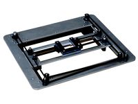
Smart Clip by Stoney by stoney2759
...starter project. http://www.kickstarter.com/projects/257195260/smarter-stand-for-ipad?ref=search
full credit to original designer
thingiverse
free

Wild Bills benbox mounts by Stoney
....
i have not made this either, i have the newer machine with the aluminium mount, scad file included if you need to make changes.
thingiverse
free

Stanley knife blade holder by Stoney
...s 2 of the bolts are through the slots in the blade.
need to run a tap through the smaller holes.
hole for additional use is 5mm.
thingiverse
free

istack ipad and iphone wall mount (parametric) by Stoney
...r can be charged hence the groove in the phone section.
included the scad file so it can be modified for other phones or tablets.
thingiverse
free

Cornelius keg ball lock hose flusher by Stoney
...ach)for my keg transfer lines with an inlet or outlet both ends.
the black version is 15.5mm diameter body and the white is 16mm.
thingiverse
free

Iphone Headphone cord holder by Stoney
...and glue them together back to back, each part is 5mm thick.
included the designspark model file if you want to change anything..
thingiverse
free

MIG spool brake by Stoney
...d before was more of a retainer with minimal tension and no adjustment. tap the 2 holes and add 15mmx3mm bolts to adjust tension.
thingiverse
free

PSVR Spectacle shield by Stoney
...it does not affect visibility or come near the face, at least not mine, so it can be left fitted for users with no specs as well.
Corexy
thingiverse
free
CoreXY by Kaz_tech
...corexy by kaz_tech
thingiverse
this is the model of corexy platform. i separately put the parts on this place.
thingiverse
free

corexy plotter by tjwan
...corexy plotter by tjwan
thingiverse
parts for corexy mill inspired by http://der-frickler.net/technik/corexyportal
thingiverse
free
ScribbleJ CoreXY Beta by ScribbleJ
...j/corexy-v1https://github.com/scribblej/corexy-v1#corexy-beta
full gallery of development photos here: http://imgur.com/a/donun
thingiverse
free
CoreXY Emblem by emkajot
...by emkajot
thingiverse
an emblem for your corexy printer.
size: 100mm x 38mm x 2mm.
update: added a version with a proper mount.
thingiverse
free

SolidCore CoreXY Carriage by shanehooper
...olidcore 3d printer. this design could be used in other corexy 3d printers.
also see:https://3ddistributed.com/corexy-3d-printer/
thingiverse
free
CoreXY 3D Printer Model by ReginaFabricam
...bricam
thingiverse
this is an original design of a corexy printer.https://www.tinkercad.com/things/jggr9qk4s4p-3d-printer-corexy
thingiverse
free

coreXY Upper structure Left
...corexy upper structure left
thingiverse
my customized corexy 3d printer upper left parts
thingiverse
free
CoreXY by frankie
...ing machines, etc. the design is described in greater detail at http://www.corexy.com . a video is at http://vimeo.com/40914530 .
thingiverse
free

Endstop block for CoreXY carriage by svkeulen
...endstop block for corexy carriage by svkeulen
thingiverse
endstop for corexy carriage
thingiverse
free
X carriage for the CoreXY MGN12 by hackerbijay
...x carriage for the corexy mgn12 by hackerbijay
thingiverse
x carriage for the corexy frame
Plasma
3d_ocean
$25
Plasma Cannon, Plasma Turret
...ily be used in any sf type of game, especially in tower defense games. - plasma cannon: 4462 polygons - textures: 6000...
3d_ocean
$19
Plasma Turret
... be used in any sf type of game, especially in tower defense games. - plasma turret: 6239 polygons - props: 522 polygons - tex...
turbosquid
$10

Plasma
... available on turbo squid, the world's leading provider of digital 3d models for visualization, films, television, and games.
3d_export
$5

plasma lamp
...plasma lamp
3dexport
detailed normal scale plasma lamp used indoors as a decorative object
turbosquid
$3

Plasma drone
...rbosquid
royalty free 3d model plasma drone for download as on turbosquid: 3d models for games, architecture, videos. (1337186)
turbosquid
$15
plasma gun
...bosquid
royalty free 3d model plasma gun for download as fbx on turbosquid: 3d models for games, architecture, videos. (1324248)
turbosquid
$12

Plasma Corvette
...id
royalty free 3d model plasma corvette for download as obj on turbosquid: 3d models for games, architecture, videos. (1442325)
turbosquid
$1
Plasma Rifle
...squid
royalty free 3d model plasma rifle for download as obj on turbosquid: 3d models for games, architecture, videos. (1485980)
turbosquid
$25

Plasma Pistol
...free 3d model plasma pistol for download as max, fbx, and obj on turbosquid: 3d models for games, architecture, videos. (1559545)
turbosquid
$50

Plasma Gun
... available on turbo squid, the world's leading provider of digital 3d models for visualization, films, television, and games.
Cutter
archibase_planet
free
Cutter
...cutter
archibase planet
cutter mill milling cutter
cutter 2 n050712 - 3d model (*.gsm+*.3ds) for interior 3d visualization.
3d_export
$10
pipe cutter
...pipe cutter
3dexport
pipe cutter
3d_export
$8
Grass Cutter
...grass cutter
3dexport
grass cutter
turbosquid
$5

Cutter
...alty free 3d model cutter for download as ige, stl, and sldpr on turbosquid: 3d models for games, architecture, videos. (1505202)
turbosquid
$29
Cutter
... available on turbo squid, the world's leading provider of digital 3d models for visualization, films, television, and games.
turbosquid
$9
Cutter
... available on turbo squid, the world's leading provider of digital 3d models for visualization, films, television, and games.
turbosquid
$3
cutter
... available on turbo squid, the world's leading provider of digital 3d models for visualization, films, television, and games.
turbosquid
$1
cutter
... available on turbo squid, the world's leading provider of digital 3d models for visualization, films, television, and games.
3d_export
free
unicorn cookie cutter
...unicorn cookie cutter
3dexport
unicorn cookie cutter, more cookie cutters here:
archive3d
free

Cutter 3D Model
...r mill milling cutter
cutter 2 n050712 - 3d model (*.gsm+*.3ds) for interior 3d visualization.