Thingiverse
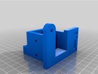
CoreXY Laser engraver by nagilum
by Thingiverse
Last crawled date: 3 years ago
Update
Check out my update/remix that adds a Z axis and further improvements to this engraver!https://www.thingiverse.com/thing:3123030
Introduction
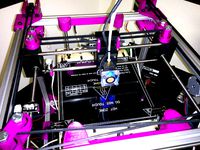
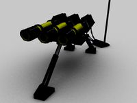
Some time ago I built a small DVD-Laser engraver but it wasn't really usable. Now this new one became reality by chance. When I upgraded my 3D printer Prusa i3 MK2 to the newer MK2S version I had a few spare parts, namely linear rods and bearings. Additionally, a 1 W blue laser from eBay was lying around unused... this is the result. ;-)
Disclaimer
This is the obligatory warning. Lasers with such high powers are dangerous and can burn or blind you, even from reflections. Don't attempt to build this if you are not familiar with high power lasers.
Good quality laser protection goggles are a must! Don't use cheap ones. And always wear them! Beware that the laser might turn on unexpectedly when the Arduino is booting (it shouldn't, but don't rely on it).
Design specs
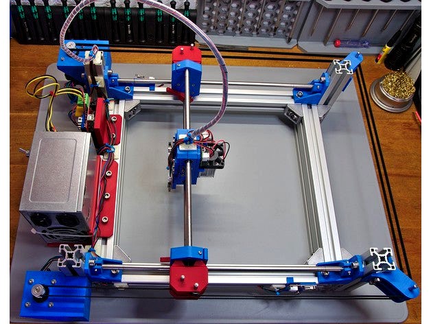
With the spare Prusa linear rods (370 mm and 330 mm) this engraver has a usable work area of 210x220 mm. You might even be able to get a few millimetres more.
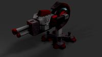
The CoreXY system is loosely inspired by other systems, especially the excellent 3D printers Hypercube by Tech2C and Hypercube Evolution by SCOTT_3D. Some other details are also modeled after these printers, such as the belt spanner system on the X carriage.
While these two systems guide their belt on the inside of the printer I decided to move the belts on the outside to get the most usable area. Instead of proper belt pulleys or idlers I used 625 ZZ ball bearings to divert the belt. For now this is working fine.
The limit switches on the X carriage were originally supposed to be triggered by the Y carriage itself. However, when the switches finally arrived they differed from the my 3D model so the additional switch activators were added... it's not elegant, but works. ;-)
Firmware
The engraver is controlled by an Arduino Mega + Ramps 1.4 board running GRBL 1.1f. These were spare parts I had in my drawer and I wasn't aware of the Arduino CNC shield when I began this build. Plus, the Ramps board seemed like an excellent choice. However, in retrospect, I would not use this board for GRBL again. There are several drawbacks compared the regular CNC shield.
no Hardware limits (the limit switches are placed on pins that are not available for external interrupts)
the spindle PWM defaults to a 12 V output. The laser driver however expects a 5 V TTL signal for power control (solved with a small GRBL patch)
Be aware that the GRBL version for the Arduino Mega has an issue when homing a CoreXY machine. It's axis locking mechanism prevents both motors to be moved at the same time when homing, i.e. the machine will move diagonally. There's a quick-fix available.
The modifications I made to GRBL are available in this fork on GitHub:GRBL CoreXY Laser engraver
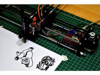
Software
To actually use the engraver you'll need to generate the proper GCode somehow. So far I've found the following tools quite useful.
JTech Inkscape Laser Plugin (contour-engraving only)
LaserWeb4 (any type of engraving)
Universal GCode Sender
Parts list
In addition to the printed parts you'll need the following parts, too. If anything is missing please let me know.
Electronics:
1x Arduino Mega / Uno
1x Ramps / Arduino CNC Shield
2x Pololu Stepper driver (A4498, DRV8825, SilentStepStick)
4x Endstops (Makerbot)
1x Laser with TTL driver
1x Power supply (e.g. old ATX)
1x Fan 12V (for the laser)
2x Nema 17 stepper motor
Mechanics:
2x 8mm Rod, 370 mm (Y axis)
2x 8mm Rod, 330 mm (X axis)
8x LM8UU linear bearing
16x Ball bearing 625 ZZ
6x 5mm steel rod, 40 mm
2x GT2 Pulley, 20 teeth
ca. 4m GT2 belt
2x Aluminum profile, 30x30 B (8 mm slot), 325 mm (parallel to Y axis)
4x Aluminum profile, 30x30 B (8 mm slot), 150 mm (for the corners)
2x Aluminum profile, 30x60 B (8 mm slot), 360 mm (parallel to X axis)
12x Corner mounting brackets 30x30
M6 T-slot nuts
M6x12 screws
M3x16 countersunk head
M3x16 head cap screw
M3x20 head cap screw
M3x25 head cap screw
TP screws, 2.5 mm (endstops, Arduino mounting, 2.5W laser driver)
M3 square nuts
M3 hex nuts
Note: The 5 mm linear rods I bought from eBay to mount the bearings had to be sanded down a bit to fit. Your mileage might vary.
Summary
After about a month of testing and tinkering I am quite satisfied with how this thing turned out. There are however a few changes / modifications I will probably implement some time in the future.
Larger working distance
The laser is placed quite close to the workpiece. This is not bad as such but unfortunately I have to move the lens so far out that it sits quite loose, probably does not capture the whole beam anymore and one cannot engrave larger objects.
Better end-stop placement
I really should have incorporated them at an earlier stage in the design process... ;-)
Motorized Z-axis
I did not implement it in this design because it would have reduced the work area. Manually adjusting the lens works fine, however, a motorized z axis will make it a lot easier.
Cable chains
While these were initially planned I chose to drop it in order to get the engraver done quicker.
ChangeLog
2019-09-21
Changed license to GPLv3.
2018-03-29
Uploaded a new laser tool mount for the common 2.5 W blue laser module.
2018-02-24
Initial upload
Check out my update/remix that adds a Z axis and further improvements to this engraver!https://www.thingiverse.com/thing:3123030
Introduction
Some time ago I built a small DVD-Laser engraver but it wasn't really usable. Now this new one became reality by chance. When I upgraded my 3D printer Prusa i3 MK2 to the newer MK2S version I had a few spare parts, namely linear rods and bearings. Additionally, a 1 W blue laser from eBay was lying around unused... this is the result. ;-)
Disclaimer
This is the obligatory warning. Lasers with such high powers are dangerous and can burn or blind you, even from reflections. Don't attempt to build this if you are not familiar with high power lasers.
Good quality laser protection goggles are a must! Don't use cheap ones. And always wear them! Beware that the laser might turn on unexpectedly when the Arduino is booting (it shouldn't, but don't rely on it).
Design specs
With the spare Prusa linear rods (370 mm and 330 mm) this engraver has a usable work area of 210x220 mm. You might even be able to get a few millimetres more.
The CoreXY system is loosely inspired by other systems, especially the excellent 3D printers Hypercube by Tech2C and Hypercube Evolution by SCOTT_3D. Some other details are also modeled after these printers, such as the belt spanner system on the X carriage.
While these two systems guide their belt on the inside of the printer I decided to move the belts on the outside to get the most usable area. Instead of proper belt pulleys or idlers I used 625 ZZ ball bearings to divert the belt. For now this is working fine.
The limit switches on the X carriage were originally supposed to be triggered by the Y carriage itself. However, when the switches finally arrived they differed from the my 3D model so the additional switch activators were added... it's not elegant, but works. ;-)
Firmware
The engraver is controlled by an Arduino Mega + Ramps 1.4 board running GRBL 1.1f. These were spare parts I had in my drawer and I wasn't aware of the Arduino CNC shield when I began this build. Plus, the Ramps board seemed like an excellent choice. However, in retrospect, I would not use this board for GRBL again. There are several drawbacks compared the regular CNC shield.
no Hardware limits (the limit switches are placed on pins that are not available for external interrupts)
the spindle PWM defaults to a 12 V output. The laser driver however expects a 5 V TTL signal for power control (solved with a small GRBL patch)
Be aware that the GRBL version for the Arduino Mega has an issue when homing a CoreXY machine. It's axis locking mechanism prevents both motors to be moved at the same time when homing, i.e. the machine will move diagonally. There's a quick-fix available.
The modifications I made to GRBL are available in this fork on GitHub:GRBL CoreXY Laser engraver
Software
To actually use the engraver you'll need to generate the proper GCode somehow. So far I've found the following tools quite useful.
JTech Inkscape Laser Plugin (contour-engraving only)
LaserWeb4 (any type of engraving)
Universal GCode Sender
Parts list
In addition to the printed parts you'll need the following parts, too. If anything is missing please let me know.
Electronics:
1x Arduino Mega / Uno
1x Ramps / Arduino CNC Shield
2x Pololu Stepper driver (A4498, DRV8825, SilentStepStick)
4x Endstops (Makerbot)
1x Laser with TTL driver
1x Power supply (e.g. old ATX)
1x Fan 12V (for the laser)
2x Nema 17 stepper motor
Mechanics:
2x 8mm Rod, 370 mm (Y axis)
2x 8mm Rod, 330 mm (X axis)
8x LM8UU linear bearing
16x Ball bearing 625 ZZ
6x 5mm steel rod, 40 mm
2x GT2 Pulley, 20 teeth
ca. 4m GT2 belt
2x Aluminum profile, 30x30 B (8 mm slot), 325 mm (parallel to Y axis)
4x Aluminum profile, 30x30 B (8 mm slot), 150 mm (for the corners)
2x Aluminum profile, 30x60 B (8 mm slot), 360 mm (parallel to X axis)
12x Corner mounting brackets 30x30
M6 T-slot nuts
M6x12 screws
M3x16 countersunk head
M3x16 head cap screw
M3x20 head cap screw
M3x25 head cap screw
TP screws, 2.5 mm (endstops, Arduino mounting, 2.5W laser driver)
M3 square nuts
M3 hex nuts
Note: The 5 mm linear rods I bought from eBay to mount the bearings had to be sanded down a bit to fit. Your mileage might vary.
Summary
After about a month of testing and tinkering I am quite satisfied with how this thing turned out. There are however a few changes / modifications I will probably implement some time in the future.
Larger working distance
The laser is placed quite close to the workpiece. This is not bad as such but unfortunately I have to move the lens so far out that it sits quite loose, probably does not capture the whole beam anymore and one cannot engrave larger objects.
Better end-stop placement
I really should have incorporated them at an earlier stage in the design process... ;-)
Motorized Z-axis
I did not implement it in this design because it would have reduced the work area. Manually adjusting the lens works fine, however, a motorized z axis will make it a lot easier.
Cable chains
While these were initially planned I chose to drop it in order to get the engraver done quicker.
ChangeLog
2019-09-21
Changed license to GPLv3.
2018-03-29
Uploaded a new laser tool mount for the common 2.5 W blue laser module.
2018-02-24
Initial upload
Similar models
thingiverse
free

3D printed for plotter or laser engraver. by tomil1
...hen you working with laser laser diode is very dangerous for eye ! always wear goggles in an adequate to laser diode wavelength !
thingiverse
free

Laserplotter Laserengraver by froetz
...4x matching toothwheels ~16x16cm tile of alloy or something similar arduino uno 9v power supply 8x lmu8 linear bearings...
thingiverse
free

XY_Plotter by modelatolyesi
...
1x ball-pen spring.
electronics:
arduino uno
cnc shield.
2x a4988 stepper driver.
9g. servo.
4x micro switch.
extension cables.
thingiverse
free

j1 CNC Laser Cutter Engraver by JeanT
...ts,
8mm polished rods, lm8uu bearings, al perforated sheet metal for table,
plastic tapes, rubber stands, jumpers, some cords,...
thingiverse
free
CoreXY_Plotter by modelatolyesi
...ap clone.)
cnc shield.
2x a4988 stepper driver.
9g servo
servo extension cable.
stepper motor cables.
12v2a adapter.
usb-b cable.
thingiverse
free

Adjustable bearing Z axis screw by zargo83
...earing for the t8 8mm z-axis screw
materials needed:
2x m3 30mm
2x m3 20mm
2x m3 nut
2x m3 t-slot nut
1x mini 608zz ball bearings
thingiverse
free

CoreXY for LM6UU and Linear Rail 6mm by nntuan
...
firmware
gnea grbl
improvement
todo: improvement to plotter: coming soon...updating...
demo
corexy test with grbl shield v3
thingiverse
free

LaCu - The fully printable CNC by Robolab
...re rigid design ;-)
the lm8uu holders and the belt clips haven´t been done by me ^^
youtube video: https://youtu.be/shcpyi8kbey
thingiverse
free

Lasercutter by Shelduck
...c related controllers should work)
and the wires to feed the stepper drivers, the controller-board, power-supply and a usb cable.
thingiverse
free

Manual CoreXY Mechanism
...ill but use 65% to be sure, it doesn't take much longer to print.
here is a video of it working: https://youtu.be/telmscfxdcs
Nagilum
thingiverse
free

Subgear XP10 Bungeemount by nagilum
...erse
a simple bungeemount for the subgear xp10 dive computer. print, clip in and insert 4 mm bungee cords at the desired length.
thingiverse
free

Spool holder - 6001 bearings by nagilum
...k of the original tush spool holder for 6001 ball bearings.
see https://www.thingiverse.com/thing:2047554 for the original thing.
thingiverse
free

Goodman handle by nagilum
...nd washers and it's good to go.
you have five m4 countersunk through-holes to attach a mounting plate for your specific lamp.
thingiverse
free

QuickConnector cap by nagilum
...sn't come out as nice as the caps. works fine nevertheless.
add an o-ring of 7.5x1.6 mm, or, alternatively, the us size #011.
thingiverse
free

Brompton wall mount by nagilum
...(note that it's a full redesign from scratch, so technically not a remix. nevertheless, credit where credits's due. :-) )
thingiverse
free
GoPro flat mount with M6 hole by nagilum
...at mount and thickened the base by a few millimetres. with this the gopro can be easily mounted to an aluminum extrusion profile.
thingiverse
free

Wine bottle lamp by nagilum
...ne bottle. the cable clamp requires 2.5 mm tp-screws, the case 3 mm tp-screws.
the led bulb is a regular e27 drop-in replacement.
thingiverse
free

Walimex videolight mount by nagilum
...le as the original part, if not more.
the original fixation screw on the side is kept and countered with an m5 nut on the inside.
thingiverse
free

Little Masterspool with filament holes by nagilum
...hen the spool rotates. to fix this i added some holes to one of the parts, two for 1.75 mm and two for 2.85 mm filament diameter.
thingiverse
free

Wire spool organizer by nagilum
...mped to any 50 mm board, like the ikea lack wall shelves.
the two parts of each organizer are simply press fitted, nothing fancy.
Corexy
thingiverse
free
CoreXY by Kaz_tech
...corexy by kaz_tech
thingiverse
this is the model of corexy platform. i separately put the parts on this place.
thingiverse
free

corexy plotter by tjwan
...corexy plotter by tjwan
thingiverse
parts for corexy mill inspired by http://der-frickler.net/technik/corexyportal
thingiverse
free
ScribbleJ CoreXY Beta by ScribbleJ
...j/corexy-v1https://github.com/scribblej/corexy-v1#corexy-beta
full gallery of development photos here: http://imgur.com/a/donun
thingiverse
free
CoreXY Emblem by emkajot
...by emkajot
thingiverse
an emblem for your corexy printer.
size: 100mm x 38mm x 2mm.
update: added a version with a proper mount.
thingiverse
free

SolidCore CoreXY Carriage by shanehooper
...olidcore 3d printer. this design could be used in other corexy 3d printers.
also see:https://3ddistributed.com/corexy-3d-printer/
thingiverse
free
CoreXY 3D Printer Model by ReginaFabricam
...bricam
thingiverse
this is an original design of a corexy printer.https://www.tinkercad.com/things/jggr9qk4s4p-3d-printer-corexy
thingiverse
free

coreXY Upper structure Left
...corexy upper structure left
thingiverse
my customized corexy 3d printer upper left parts
thingiverse
free
CoreXY by frankie
...ing machines, etc. the design is described in greater detail at http://www.corexy.com . a video is at http://vimeo.com/40914530 .
thingiverse
free

Endstop block for CoreXY carriage by svkeulen
...endstop block for corexy carriage by svkeulen
thingiverse
endstop for corexy carriage
thingiverse
free
X carriage for the CoreXY MGN12 by hackerbijay
...x carriage for the corexy mgn12 by hackerbijay
thingiverse
x carriage for the corexy frame
Engraver
turbosquid
$8
Engraved Sword
...alty free 3d model engraved sword for download as max and fbx on turbosquid: 3d models for games, architecture, videos. (1168563)
turbosquid
$10
Engraved tiger
...ree 3d model engraved tiger for download as max, obj, and fbx on turbosquid: 3d models for games, architecture, videos. (1298214)
turbosquid
$1

Engraver(General)
... available on turbo squid, the world's leading provider of digital 3d models for visualization, films, television, and games.
turbosquid
$19
Seax Knife Engraved
...model seax knife engraved for download as blend, fbx, and obj on turbosquid: 3d models for games, architecture, videos. (1497294)
3d_export
$5
scary monster engraving
...nal engraving for 3d printing will give your environment an exotic look! it will look great if you paint it in the color of stone
turbosquid
$59
Emerald Engraving Ring
... available on turbo squid, the world's leading provider of digital 3d models for visualization, films, television, and games.
turbosquid
$23
Runes Engraving Set
... available on turbo squid, the world's leading provider of digital 3d models for visualization, films, television, and games.
turbosquid
$15
Decoration Engraved table
... available on turbo squid, the world's leading provider of digital 3d models for visualization, films, television, and games.
turbosquid
$8
Viking helmet with engraved
...met with engraved for download as c4d, 3ds, dxf, fbx, and obj on turbosquid: 3d models for games, architecture, videos. (1618783)
turbosquid
$5

Engraved coffee cup
...ved coffee cup for download as blend, dae, fbx, obj, and gltf on turbosquid: 3d models for games, architecture, videos. (1713648)
Laser
3d_export
$5
laser
...laser
3dexport
a 3d laser
3d_export
free
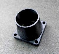
cnc 3dp laser nozzle for 2w laser opt lasers
...logy that gave birth to cutting and engraving laser heads this laser nozzle was designed for, read the article in the link below:
3d_export
free
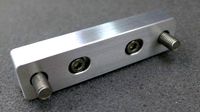
cnc laser mount opt lasers
...eive the engraving and cutting laser heads this cnc machine laser mount was designed for, read the article on the following page:
turbosquid
$20

Laser
... available on turbo squid, the world's leading provider of digital 3d models for visualization, films, television, and games.
turbosquid
$15
Laser
... available on turbo squid, the world's leading provider of digital 3d models for visualization, films, television, and games.
turbosquid
$3
Laser
... available on turbo squid, the world's leading provider of digital 3d models for visualization, films, television, and games.
3d_export
$5

laser sword
...laser sword
3dexport
it is a blue laser sword with a metal frame
3d_ocean
$19
Laser Turret
...be used in any sf type of game, especially in tower defense games. - laser turret: 3025 polygons - props: 270 polygons - textu...
3d_export
free
workbee cnc laser mount for opt lasers
...the specifications of engraving and cutting laser heads this mount was designed for, please take a look at the following website:
3d_export
free

shapeoko cnc laser mount for opt lasers
...ind out the opportunities that adding a cutting and engraving laser head to your cnc can bring, take a look at the website below: