Thingiverse
Control MOSFET module directly from Arduino output pin by Paran0ic
by Thingiverse
Last crawled date: 4 years, 7 months ago
How to modify MOSFET module (http://s.click.aliexpress.com/e/I2FMBU7) to control from 5V digital output?
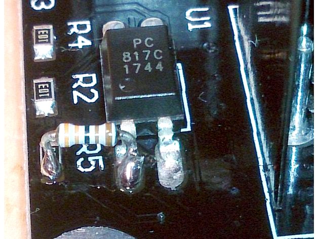
You need to change R5 value from 10k ohm to about 2.5k ohm. I soldered additional 3.3k ohm resistor parallel to R5.
Parts:
MOSFET module: http://s.click.aliexpress.com/e/I2FMBU7
Resistor 3.3k ohm (maybe 2.7 or 3.9 k ohm)
And pillar washer M3*15 for MOSFET board support.
Why?
The input of MOSFET module must be connected to RAMPS (or another 3D printer motherboard) power output. It is no problem on simple config (bed, fan, extruder). But if you want to control additional controller fan, or two extruders, fan and hot bed, you need 4 or more power outputs.
RAMPS have a lot of free digital output, but MOSFET boards needs 12V (above 8V) in control input to switch on. MOSFET modules uses photocoupler PC817 (http://akizukidenshi.com/download/PC817C.pdf - lose about 1.2V) to isolate input and output circuits. Additionally it uses rectifiers (diode bridge, lose about 1.2V) to not to pay attention to the polarity of the input.
At the end, 5V from digital output is too small to control optocupler through 10k resistor. You need to modify value R5, to obtain sufficient current for optocoupler.
Modified MOSFET module works with 5V inputs and it is safe to control it with 12V inputs.