Thingiverse
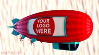
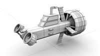
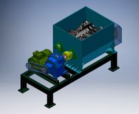
CONCEPTUAL DESIGN OF A HYBRID ELECTRIC BLIMP WITH COMPRESSED AIR SYSTEM by Isarts3d
by Thingiverse
Last crawled date: 2 years, 11 months ago
01- Introduction- CONCEPTUAL DESIGN OF A HYBRID ELECTRIC BLIMP WITH COMPRESSED AIR SYSTEM
Currently with the growing demand for energy, but with pespectivas of declining fossil fuels, the world turns to alternative renewable sources, mainly derived from sunlight, both in the use of wind technologies, and photovoltaic cells or tidal waves.
It comes to concern for the environment, constantentemente deteriorating due to the use of energy derived from fossil sources like oil and coal.
In the area of air transport, where the predominant use of fossil fuels used in aircraft, there is a tendency for the world to turn to old technologies that utizam less fossil fuel and hence less polluting, airships.
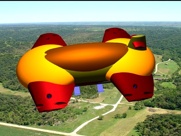
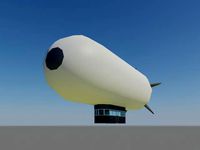
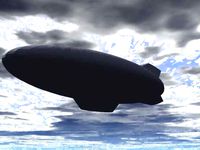
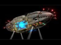
In this sense, I developed a conceptual design of an airship with an innovative propulsion system, combining compressed air with normal temperature with hot air, and the use of two types of gas: helium and hot air.
It is a hybrid airship for several reasons: First, because it uses two kinds of gases helium and hot air. Second, because the engine has to be hybrid, conventional and electric. Also the design of the airship, as it has wings, like an airplane.
Is therefore a conceptual design, drawings were made freely without calculations or detailing. Only the exposure of an idea in 3D drawings, to be examined for their viability.
In addition, other innovations have been incorporated as a system of maneuverability, allowing the airship back, move forward or laterally, turning on itself horizontally.
For the production of compressed air, has a main hybrid engine that captures the air through an opening on the front of the ship.
The wings are located electric motors that produce hot and turbines, horizontal and vertical air.
The intention is to coat the top of the plates photovoltaic flexible nature in order to produce electrical energy to power the engines, and wings at the top, to produce hot air to be mixed with air at normal temperature in the turbines.
The load module, located on the underside of the ship, has four ramps that also function as complementary lower wings, which theoretically help stabilize the ship. Moreover, they have the function of fixing the airship on track.
This module may have the option to passengers, like a flying bus.
Images its shape can be seen in figures 1 to 4.
02-Overview of the distribution of gases in the hybrid airship (Image5-CorteGeral)
Are two types of gases used in drigível: Helium and hot air.
Helium gas is distributed think-and four pockets: In front, behind, above and below the body of the ship. Already warm air located in a pocket in the center of the nave.
Helium always keep the amount constant, while the hot air temperature would vary according to the convenience.
For example: being empty the load module, the air would have to room temperature, and when the load module, the pocket would with lighter warm air, contributing to the ship rise more easily.
03- Scheme of the main module (Image6-General Scheme) compressed air - The main system air intake located on the front of the ship (01). Inside is a chamber (05) where there are two sets of systems so as to produce the compressed air for heating the air, which feed the central pocket of warm air (02) located over the load module (03).
04- Scheme of distribution of the compressed air chamber for the wings (Image7-Scheme-General Picture1)
Main motor hybrid (conventional fuel and electric) (06) follows the compressed air for the four wings (04) where there are the vertical (09) and horizontal (10) turbines.
05-General view of the distribution of compressed air and hot air (Image7-Scheme-General Picture1) schemes
From the central cabin (05), the compressed air goes to the wings (04), front, and rear wings, the pipe (13).
The wings (04) are other systems such as hot air to produce (08) and the other for maneuvering the ship (12). It is also lying on the vertical (09) and horizontal turbine (10) receiving the compressed air passing through another discharge through the system (11).
06- central hall of the main processing systems for air (05) - (Image8-Camara-Picture1)
It is located on the front of the ship, and is divided into two parts: At the bottom are the two compressed air cylinders (6.6), and on the upper floor, hybrid electric and (6.1) engines, in addition to the system heating of air (07).
Access to this cubicle is through an opening in the floor (6.9) via a cage (6.10).
6.1-The main engine of the hybrid nature (6.1) - It finds itself coupled centrifugal pump (6.2) that sucks air atravéz channel (6.3) connecting the front of the ship.
The air is directed to two cylinders (6.6), sendos before last for a settlement through an auxiliary electric boma (6.4). Hence the first cylinder distributes compressed air to the two front wings, and the second to rear (6.7).
07- Heating the air that feeds the central pocket (02). (Image8-Camara-Picture2)
Is located on the second floor level of the chamber.
It consists of an electric pump (07) coupled to a centrifugal pump (7.1) sucking air from the chamber (05) and also from engine exhaust (6.10).
The hot air from the engine passes through a filter cleaning (6.9) before entering the centrifugal pump.
This mixture of air still passes through a heater (7.2) and then proceed to the pocket of warm air (02) located in the center of the nave.
08- Systems located in asas- (Image9-EsquemaAsa)
Discharge system primarily The compressed air coming from the engine (6.7.1) follows the central air system to another booster (11) before reaching the vertical (09) and horizontal (10) turbines.
- Systems of production of hot-air (08)
Produces hot air to blend the compressed air in the turbines.
- System for maneuvering the ship (12), rotating the ends of the beaks.
System 09- the main air discharge (11) (image10-BombaRecalque-Picture1)
The compressed air that comes from the core engine passes through another booster before entering the air cylinder (11.2), produced by an electric motor (11), in order to further increase the pressure inside it.
Hence, it follows both the horizontal turbines (9.10), as vertical, the hoses (11.4,11.5)
divided by fork (11.3).
10-production system for hot air (image11-SistemaArQuente-Picture1)
Through an electric motor (08) coupled in a centrifugal pump (8.1), the heated air is withdrawn from the hot air pocket (4.1) of the upper wing (04) and thus driven to the air cylinder (8.5) . Before that passes through a junction (8.4) which, connected to an auxiliary electric motor (8.3), air is repressed to give the pressure inside the cylinder.
The cylinder (8.5), the compressed air passes through a heater (8.6), raising the temperature further, and is then divided into two parts through the bifurcation Y (8.7) and following the hoses (8.8, 8.9) to the horizontal and vertical turbines, where it mixes with the compressed air from the main engine.
10.1- pocket of hot air on the wings (image11-SistemaArQuente-Picture2) - This illustration shows another more clearly the air pocket (4.1), situated on top of the wing (04), which is metal, and so the air is heated by the sun.
11-pressurization system for air nozzles to maneuver the airship híbrido- (Image12-Bicomp-Picture1)
A specific system to maneuver the airship finds itself installed in the wing of the ship. It consists of an electric motor (12) coupled to a centrifugal pump captures the hot air from the top of the wing where no hot air pocket (4.1).
This captured air hot air pocket (4.1) of the wing repressed by the electric motor for compressed air (12.3) cylinder, goes directly to the nozzle actuator (12.1), by means of a sleeve (12.4) which passes underneath the horizontal turbine (10).
Besides the captured air pocket Wing also brings another source - the pocket of the center of the nave, through a pipe that comes from the pocket of the main body of the ship (12.5) (Image12-Bicomp-Picture2).
The idea is that when there is need to exchange air in this pocket for a change in temperature according to convenience, this system also works accordingly.
11.1- Nozzle maneuver (12.1) - It is located at the wing, and can rotate 360 degrees.
Is this atravéz swivel spout that the ship can maneuver forward, backward, and to turn on itself, and around laterally (image13-Maneuver-Picture1).
12-Maneuverability of aeronave- (image13-Maneuver)
One of the features that stand out in the hybrid airship is its maneuverability.
By design, it is capable of maneuvers that have no existing aircraft, whether plane or helicopter drones:
This is possible thanks to the maneuvering system composed of compressed air, with movable nozzles installed at the end of the four wings.
To facilitate visibility of nozzles deliberately upped its dimensions in relation to the ship, to explain their functions.
Maneuvering of the airship consists of:
Back slowly (1) - All four nozzles directed forward (2), as shown in the next image (image13-Maneuver-Picture2)
Next lentamente- All nozzles directed back to the ship recedes.
Around laterally (1), for both left and right
With all nozzles (2) facing the left direction, the ship will move laterally to the right side (image13-Maneuver-Picture3)
Reversing the direction of the nozzles, the ship will shift to the left
Turn on itself (image13-Maneuver-Picture4)
With the tips of the two wings (2), right side facing forward, and the left side facing back, the ship will rotate in the opposite direction (1) of the output of compressed air jet coming out of the nozzles.
Reversing the position of all nozzles, the ship will rotate in the opposite direction.
13-Camera access the main processing systems ar- (image14-AcessoCamara-Picture1)
Access to the chamber (05) is through an opening in the floor (6:12), in the center, which lies between the two compressed air cylinders (6.6).
14-cage transport (6:13) - (image14-AcessoCamara-Picture2)
To gain access to the chamber of engines (5), instead of a door, the access is on the ground (6:12).
It is necessary to make use of a cage (6:13) who falls for an opening that also passes on housing ship, on its bottom.
To support this cage, there will be a lift system by means of two steel cables, not shown in the drawing.
This cage will pass right in front of the cockpit of the load module.
15-Turbine System comprimido- air (Image15-turbines-Picture1)
The assembly of the turbine compressed air is formed by four basic elements: a turbine (9,10) itself, the bifunctional helix (9.4), the support (9.1) in a ring shape to set the turbine in the wing (4.3 ) and the bearing (9.5) that holds the propeller.
Functioning of turbina- Compressed air coming from the main engine by hose (11.4) enters the turbine at the opening at the top, and just below, the heated air enters the hose (8.9).
This mixture of compressed air at different temperatures, plus the added volume will cause a greater pressure on the turbine by the expansion of hot air. Thus power will be greater thrust of the turbine.
The air expelled from the exit of the turbine in circular (9.2) form is still harnessed to move a set of propellers.
15.1- Propellers of bifunctional turbinas- (Image15-turbines-Picture2)
These propellers are of two types: The inner part (9.3), helical shape, is receiving the blow jet of compressed air leaving the turbine, causing it to rotate, and also rotates consequenteme outside (9.4) of propeller sucking air from the top of the vertical turbine, or horizontally in front of the turbine.
Thus, besides the buoyancy caused by the jet of compressed air leaving the turbine, the propeller also contributes to raise the ship.
The turbine is fixed to the cylindrical opening by means of a ring (9.1) in both the top and the bottom of this support.
The set of blades (9.3, 9.4) rotates freely in the bearing (9.5) which is fixed in the cylindrical opening of the wing (4.3).
16-System repression of auxiliary pump (image10-BombaRecalque-Picture2)
Typical air discharge system, consisting of an auxiliary electric pump (1), the helical screw (3) and fork side tube (2).
The compressed air enters the input side of the junction (2), and the passage for the pipe, is repressed by the electric pump (1) through the helix coil in the straight part for joining the compressed air cylinder (4).
The intention of this system is to strengthen further the compressed air in the cylinder, and consequently increasing the power of your action.
This system has been implanted in all cylinders of the compressed air in the ship.
Created this way to boost the compressed air, and therefore may be questionable efficiency. There may be more efficient ways to accomplish this function.
Deploy a system with pistons, like a conventional compressor, I thought that would result in additional weight, hence why I thought this simplest form.
17-module load-(Image16-MóduloCarga-Picture1)
The load module (02) finds itself attached to the bottom of the hybrid airship (01), and has two doors (05) large enough to allow a forklift to load.
17.1- Ramps For access-entry module, such as forklifts or persons, if the module is for people, there are four ramps (06) which actually also has other functions. They serve as landing gear, and set the ship on track through the holes (07) at their ends, where locks can be placed.
Moreover, these ramps also act as auxiliary wings, which can help with stability during flight.
17.2- Cabin pilot-course Located on the front of the ship, a higher load compared to the sector, and side windows and central heating.
17.3- Interior of charge- (Image16-MóduloCarga-Picture2) module
Has ample internal space, sufficient for entry and maneuvering of forklifts with load.
The entrance to the cockpit is done using a ladder (08), as his floor is higher than in the cargo sector.
17.4- Cutaway view of the load-(Image16-VistaemCortes-Picture2) module
The sectional view of the load (02) module and the main part (01) is displayed clearly the sloping floor of the cockpit (09) with the floor of the loading dock and the placement of the front and side windows (03).
There are also the visualization of the position of the load in relation to the camera module of the engines of the ship, as well as access to it.
18-Final considerations:
As pointed out in the introduction, this is a conceptual design, where ideas were introduced freely, without any calculation or steeper deepening components. Only indication of the main elements, with representation in them, similar to 3D designs that are truly.
What needs to be analyzed are systems developed to see if they are viable or not, such as:
- System turbina- are mixed with normal compressed air hot to give greater pressure inside the bifunctional helix, where the compressed air expelled by the output from the turbine directly affects internal helical propellers, air and with it, the external propellers, to internal solidarity, moves in order to suck air from the top, and thereby helping the thrust of the turbine.
So would two systems working simultaneously on the buoyancy of the ship: the thrust of the turbine and the movement of the outer propellers.
- The auxilidar recalque- pump system there also to check their efficiency, in order to further increase the pressure in the compressed air cylinders.
- Combination of two types of gases- Another factor to be checked is the combination that suggest the project with respect to the gases responsible for the elevation of the airship. The helium gas with hot air.
In the design set helium four pockets of the main body of the spacecraft, and also in the wings, and the warm air would occupy the central part thereof. The helium gas to remain constant amount, while the hot air temperature vary depending on the convenience. The hot air also occupy a pocket on top of the wings, collected to blend with compressed air at normal temperature in the turbines.
However, there may be no advantage to justify this system. Then, another suggestion is to leave only the helium gas and thus eliminate the hot air system.
- System maneuverability of navigable Another system to be analyzed.
I created a rotary nozzles located at the ends of the wing, powered tablet, which according to their direction, the ship can move slowly back, move laterally either to the right and to the left, and turn on itself.
- System of production of solar-energy for power all the electric motors of the airship, suggested installing on top of the main body of the airship, flexible photovoltaic plates, with the exception of the wings, where the upper part of this would have to be metal to air heating in the pocket of her part.
- Landing gear shaped rampa- Another innovation being examined: I designed the gear-shaped ramp, so that it has multiple uses.
As landing gear, the airship can be stuck in the track surface, pass through latches that the holes at the ends.
Works as ramp passage of forklifts to load the load module.
Can aid in flight stability of the ship, as these ramps can make the function of additional wings.
- Finally, the design of the aircraft itself may be challenged by their aerodynamics.
I am not an engineer or expert in this field and not have higher education. I am a self-taught designer who designs as ideas emerge only.
I wish this conceptual design of this hybrid airship was analyzed by experts to verify the feasibility of all the ideas presented in it.
If companies also interested in continuing the development of this project, please contact me.
For English, the text is automatically translated by google translator. So it may be that many words slipped out of context.
This description of the project, with a wealth of illustrations, is available for download in pdf, in both Portuguese and English.
Project- Conceptual design of a hybrid electric and compressed air airship
Author of Project- Issamu Aono Ichiya
Country of origin- Brazil
Location- actualization Japan
Currently with the growing demand for energy, but with pespectivas of declining fossil fuels, the world turns to alternative renewable sources, mainly derived from sunlight, both in the use of wind technologies, and photovoltaic cells or tidal waves.
It comes to concern for the environment, constantentemente deteriorating due to the use of energy derived from fossil sources like oil and coal.
In the area of air transport, where the predominant use of fossil fuels used in aircraft, there is a tendency for the world to turn to old technologies that utizam less fossil fuel and hence less polluting, airships.
In this sense, I developed a conceptual design of an airship with an innovative propulsion system, combining compressed air with normal temperature with hot air, and the use of two types of gas: helium and hot air.
It is a hybrid airship for several reasons: First, because it uses two kinds of gases helium and hot air. Second, because the engine has to be hybrid, conventional and electric. Also the design of the airship, as it has wings, like an airplane.
Is therefore a conceptual design, drawings were made freely without calculations or detailing. Only the exposure of an idea in 3D drawings, to be examined for their viability.
In addition, other innovations have been incorporated as a system of maneuverability, allowing the airship back, move forward or laterally, turning on itself horizontally.
For the production of compressed air, has a main hybrid engine that captures the air through an opening on the front of the ship.
The wings are located electric motors that produce hot and turbines, horizontal and vertical air.
The intention is to coat the top of the plates photovoltaic flexible nature in order to produce electrical energy to power the engines, and wings at the top, to produce hot air to be mixed with air at normal temperature in the turbines.
The load module, located on the underside of the ship, has four ramps that also function as complementary lower wings, which theoretically help stabilize the ship. Moreover, they have the function of fixing the airship on track.
This module may have the option to passengers, like a flying bus.
Images its shape can be seen in figures 1 to 4.
02-Overview of the distribution of gases in the hybrid airship (Image5-CorteGeral)
Are two types of gases used in drigível: Helium and hot air.
Helium gas is distributed think-and four pockets: In front, behind, above and below the body of the ship. Already warm air located in a pocket in the center of the nave.
Helium always keep the amount constant, while the hot air temperature would vary according to the convenience.
For example: being empty the load module, the air would have to room temperature, and when the load module, the pocket would with lighter warm air, contributing to the ship rise more easily.
03- Scheme of the main module (Image6-General Scheme) compressed air - The main system air intake located on the front of the ship (01). Inside is a chamber (05) where there are two sets of systems so as to produce the compressed air for heating the air, which feed the central pocket of warm air (02) located over the load module (03).
04- Scheme of distribution of the compressed air chamber for the wings (Image7-Scheme-General Picture1)
Main motor hybrid (conventional fuel and electric) (06) follows the compressed air for the four wings (04) where there are the vertical (09) and horizontal (10) turbines.
05-General view of the distribution of compressed air and hot air (Image7-Scheme-General Picture1) schemes
From the central cabin (05), the compressed air goes to the wings (04), front, and rear wings, the pipe (13).
The wings (04) are other systems such as hot air to produce (08) and the other for maneuvering the ship (12). It is also lying on the vertical (09) and horizontal turbine (10) receiving the compressed air passing through another discharge through the system (11).
06- central hall of the main processing systems for air (05) - (Image8-Camara-Picture1)
It is located on the front of the ship, and is divided into two parts: At the bottom are the two compressed air cylinders (6.6), and on the upper floor, hybrid electric and (6.1) engines, in addition to the system heating of air (07).
Access to this cubicle is through an opening in the floor (6.9) via a cage (6.10).
6.1-The main engine of the hybrid nature (6.1) - It finds itself coupled centrifugal pump (6.2) that sucks air atravéz channel (6.3) connecting the front of the ship.
The air is directed to two cylinders (6.6), sendos before last for a settlement through an auxiliary electric boma (6.4). Hence the first cylinder distributes compressed air to the two front wings, and the second to rear (6.7).
07- Heating the air that feeds the central pocket (02). (Image8-Camara-Picture2)
Is located on the second floor level of the chamber.
It consists of an electric pump (07) coupled to a centrifugal pump (7.1) sucking air from the chamber (05) and also from engine exhaust (6.10).
The hot air from the engine passes through a filter cleaning (6.9) before entering the centrifugal pump.
This mixture of air still passes through a heater (7.2) and then proceed to the pocket of warm air (02) located in the center of the nave.
08- Systems located in asas- (Image9-EsquemaAsa)
Discharge system primarily The compressed air coming from the engine (6.7.1) follows the central air system to another booster (11) before reaching the vertical (09) and horizontal (10) turbines.
- Systems of production of hot-air (08)
Produces hot air to blend the compressed air in the turbines.
- System for maneuvering the ship (12), rotating the ends of the beaks.
System 09- the main air discharge (11) (image10-BombaRecalque-Picture1)
The compressed air that comes from the core engine passes through another booster before entering the air cylinder (11.2), produced by an electric motor (11), in order to further increase the pressure inside it.
Hence, it follows both the horizontal turbines (9.10), as vertical, the hoses (11.4,11.5)
divided by fork (11.3).
10-production system for hot air (image11-SistemaArQuente-Picture1)
Through an electric motor (08) coupled in a centrifugal pump (8.1), the heated air is withdrawn from the hot air pocket (4.1) of the upper wing (04) and thus driven to the air cylinder (8.5) . Before that passes through a junction (8.4) which, connected to an auxiliary electric motor (8.3), air is repressed to give the pressure inside the cylinder.
The cylinder (8.5), the compressed air passes through a heater (8.6), raising the temperature further, and is then divided into two parts through the bifurcation Y (8.7) and following the hoses (8.8, 8.9) to the horizontal and vertical turbines, where it mixes with the compressed air from the main engine.
10.1- pocket of hot air on the wings (image11-SistemaArQuente-Picture2) - This illustration shows another more clearly the air pocket (4.1), situated on top of the wing (04), which is metal, and so the air is heated by the sun.
11-pressurization system for air nozzles to maneuver the airship híbrido- (Image12-Bicomp-Picture1)
A specific system to maneuver the airship finds itself installed in the wing of the ship. It consists of an electric motor (12) coupled to a centrifugal pump captures the hot air from the top of the wing where no hot air pocket (4.1).
This captured air hot air pocket (4.1) of the wing repressed by the electric motor for compressed air (12.3) cylinder, goes directly to the nozzle actuator (12.1), by means of a sleeve (12.4) which passes underneath the horizontal turbine (10).
Besides the captured air pocket Wing also brings another source - the pocket of the center of the nave, through a pipe that comes from the pocket of the main body of the ship (12.5) (Image12-Bicomp-Picture2).
The idea is that when there is need to exchange air in this pocket for a change in temperature according to convenience, this system also works accordingly.
11.1- Nozzle maneuver (12.1) - It is located at the wing, and can rotate 360 degrees.
Is this atravéz swivel spout that the ship can maneuver forward, backward, and to turn on itself, and around laterally (image13-Maneuver-Picture1).
12-Maneuverability of aeronave- (image13-Maneuver)
One of the features that stand out in the hybrid airship is its maneuverability.
By design, it is capable of maneuvers that have no existing aircraft, whether plane or helicopter drones:
This is possible thanks to the maneuvering system composed of compressed air, with movable nozzles installed at the end of the four wings.
To facilitate visibility of nozzles deliberately upped its dimensions in relation to the ship, to explain their functions.
Maneuvering of the airship consists of:
Back slowly (1) - All four nozzles directed forward (2), as shown in the next image (image13-Maneuver-Picture2)
Next lentamente- All nozzles directed back to the ship recedes.
Around laterally (1), for both left and right
With all nozzles (2) facing the left direction, the ship will move laterally to the right side (image13-Maneuver-Picture3)
Reversing the direction of the nozzles, the ship will shift to the left
Turn on itself (image13-Maneuver-Picture4)
With the tips of the two wings (2), right side facing forward, and the left side facing back, the ship will rotate in the opposite direction (1) of the output of compressed air jet coming out of the nozzles.
Reversing the position of all nozzles, the ship will rotate in the opposite direction.
13-Camera access the main processing systems ar- (image14-AcessoCamara-Picture1)
Access to the chamber (05) is through an opening in the floor (6:12), in the center, which lies between the two compressed air cylinders (6.6).
14-cage transport (6:13) - (image14-AcessoCamara-Picture2)
To gain access to the chamber of engines (5), instead of a door, the access is on the ground (6:12).
It is necessary to make use of a cage (6:13) who falls for an opening that also passes on housing ship, on its bottom.
To support this cage, there will be a lift system by means of two steel cables, not shown in the drawing.
This cage will pass right in front of the cockpit of the load module.
15-Turbine System comprimido- air (Image15-turbines-Picture1)
The assembly of the turbine compressed air is formed by four basic elements: a turbine (9,10) itself, the bifunctional helix (9.4), the support (9.1) in a ring shape to set the turbine in the wing (4.3 ) and the bearing (9.5) that holds the propeller.
Functioning of turbina- Compressed air coming from the main engine by hose (11.4) enters the turbine at the opening at the top, and just below, the heated air enters the hose (8.9).
This mixture of compressed air at different temperatures, plus the added volume will cause a greater pressure on the turbine by the expansion of hot air. Thus power will be greater thrust of the turbine.
The air expelled from the exit of the turbine in circular (9.2) form is still harnessed to move a set of propellers.
15.1- Propellers of bifunctional turbinas- (Image15-turbines-Picture2)
These propellers are of two types: The inner part (9.3), helical shape, is receiving the blow jet of compressed air leaving the turbine, causing it to rotate, and also rotates consequenteme outside (9.4) of propeller sucking air from the top of the vertical turbine, or horizontally in front of the turbine.
Thus, besides the buoyancy caused by the jet of compressed air leaving the turbine, the propeller also contributes to raise the ship.
The turbine is fixed to the cylindrical opening by means of a ring (9.1) in both the top and the bottom of this support.
The set of blades (9.3, 9.4) rotates freely in the bearing (9.5) which is fixed in the cylindrical opening of the wing (4.3).
16-System repression of auxiliary pump (image10-BombaRecalque-Picture2)
Typical air discharge system, consisting of an auxiliary electric pump (1), the helical screw (3) and fork side tube (2).
The compressed air enters the input side of the junction (2), and the passage for the pipe, is repressed by the electric pump (1) through the helix coil in the straight part for joining the compressed air cylinder (4).
The intention of this system is to strengthen further the compressed air in the cylinder, and consequently increasing the power of your action.
This system has been implanted in all cylinders of the compressed air in the ship.
Created this way to boost the compressed air, and therefore may be questionable efficiency. There may be more efficient ways to accomplish this function.
Deploy a system with pistons, like a conventional compressor, I thought that would result in additional weight, hence why I thought this simplest form.
17-module load-(Image16-MóduloCarga-Picture1)
The load module (02) finds itself attached to the bottom of the hybrid airship (01), and has two doors (05) large enough to allow a forklift to load.
17.1- Ramps For access-entry module, such as forklifts or persons, if the module is for people, there are four ramps (06) which actually also has other functions. They serve as landing gear, and set the ship on track through the holes (07) at their ends, where locks can be placed.
Moreover, these ramps also act as auxiliary wings, which can help with stability during flight.
17.2- Cabin pilot-course Located on the front of the ship, a higher load compared to the sector, and side windows and central heating.
17.3- Interior of charge- (Image16-MóduloCarga-Picture2) module
Has ample internal space, sufficient for entry and maneuvering of forklifts with load.
The entrance to the cockpit is done using a ladder (08), as his floor is higher than in the cargo sector.
17.4- Cutaway view of the load-(Image16-VistaemCortes-Picture2) module
The sectional view of the load (02) module and the main part (01) is displayed clearly the sloping floor of the cockpit (09) with the floor of the loading dock and the placement of the front and side windows (03).
There are also the visualization of the position of the load in relation to the camera module of the engines of the ship, as well as access to it.
18-Final considerations:
As pointed out in the introduction, this is a conceptual design, where ideas were introduced freely, without any calculation or steeper deepening components. Only indication of the main elements, with representation in them, similar to 3D designs that are truly.
What needs to be analyzed are systems developed to see if they are viable or not, such as:
- System turbina- are mixed with normal compressed air hot to give greater pressure inside the bifunctional helix, where the compressed air expelled by the output from the turbine directly affects internal helical propellers, air and with it, the external propellers, to internal solidarity, moves in order to suck air from the top, and thereby helping the thrust of the turbine.
So would two systems working simultaneously on the buoyancy of the ship: the thrust of the turbine and the movement of the outer propellers.
- The auxilidar recalque- pump system there also to check their efficiency, in order to further increase the pressure in the compressed air cylinders.
- Combination of two types of gases- Another factor to be checked is the combination that suggest the project with respect to the gases responsible for the elevation of the airship. The helium gas with hot air.
In the design set helium four pockets of the main body of the spacecraft, and also in the wings, and the warm air would occupy the central part thereof. The helium gas to remain constant amount, while the hot air temperature vary depending on the convenience. The hot air also occupy a pocket on top of the wings, collected to blend with compressed air at normal temperature in the turbines.
However, there may be no advantage to justify this system. Then, another suggestion is to leave only the helium gas and thus eliminate the hot air system.
- System maneuverability of navigable Another system to be analyzed.
I created a rotary nozzles located at the ends of the wing, powered tablet, which according to their direction, the ship can move slowly back, move laterally either to the right and to the left, and turn on itself.
- System of production of solar-energy for power all the electric motors of the airship, suggested installing on top of the main body of the airship, flexible photovoltaic plates, with the exception of the wings, where the upper part of this would have to be metal to air heating in the pocket of her part.
- Landing gear shaped rampa- Another innovation being examined: I designed the gear-shaped ramp, so that it has multiple uses.
As landing gear, the airship can be stuck in the track surface, pass through latches that the holes at the ends.
Works as ramp passage of forklifts to load the load module.
Can aid in flight stability of the ship, as these ramps can make the function of additional wings.
- Finally, the design of the aircraft itself may be challenged by their aerodynamics.
I am not an engineer or expert in this field and not have higher education. I am a self-taught designer who designs as ideas emerge only.
I wish this conceptual design of this hybrid airship was analyzed by experts to verify the feasibility of all the ideas presented in it.
If companies also interested in continuing the development of this project, please contact me.
For English, the text is automatically translated by google translator. So it may be that many words slipped out of context.
This description of the project, with a wealth of illustrations, is available for download in pdf, in both Portuguese and English.
Project- Conceptual design of a hybrid electric and compressed air airship
Author of Project- Issamu Aono Ichiya
Country of origin- Brazil
Location- actualization Japan
Similar models
grabcad
free

Jet engine with propeller shaft
...compressed air, burning the mixture in the combustor, and then passing the hot, high pressure air through a turbine and a nozzle.
thingiverse
free

CONCEPTUAL DESIGN OF A HYBRID ELECTRIC DRONE AND COMPRESSED AIR by Isarts3d
...ooking good, until the drone designed to look like a huge bee. i liked the suggestion, then, from now on, this will be your name.
grabcad
free

Jet Engine
...led the turbine. the turbine is attached to the same shaft as the compressor. spinning the turbine causes the compressor to spin.
3dwarehouse
free

hybrid helium-hotair semi ridgid airship
...hybrid helium-hotair semi ridgid airship
3dwarehouse
hybrid helium-hotair semi ridgid airship with estimated lift figures
grabcad
free

Cylinder for air or helium
...cylinder for air or helium
grabcad
cylinder for air or helium
3dwarehouse
free

hybrid hotair-helium semi ridgid airship
...nter black area being propane/solar heated that would also warm the neighboring cells promoting expansion, increasing total lift.
grabcad
free

Orenda Jet Engine 9/10 Turbine nozzle
...ng and by the cooler bypass air from the outer parts of the combuster. i have left out the bolts and other fasteners for clarity.
thingiverse
free

Modular Electric Rocket Concept by Raqia-Design
... push off of)
photovoltaic hull film (thin solar cell layer)
internal flow compression.
rudders in stabilizers.
scalable concept.
grabcad
free

Viper 8 jet engine turbine
...oud to provide cooling air for the turbine bearing and disc before going into the exhaust section centre again providing cooling.
grabcad
free

Hydraulic briquette press machine
... -and a lot of components for hydraulic system
Isarts3D
thingiverse
free
Support for Smartphone by Isarts3d
... keep the headset in a mobile base which is at the bottom of the holder.
moreover, it also serves to store the actual smartphone.
thingiverse
free

Bomboniere by Isarts3d
...e introduction of this key hole because of the way it is flush with the internal divisions, the chocolates hamper this operation.
thingiverse
free

Object holder with clock by Isarts3d
...e same color of the filament.
text translated by google translate from portuguese to english.
contact by email isarts3d@gmail.com
thingiverse
free

Abajour flower style by Isarts3d
...ated by google translator. so few words can get out of context.
any questions or problems, contact me by email isarts3d@gmail.com
thingiverse
free
Universal Mobile Stand for Tablet by Isarts3d
...re the headset in a practical way.
for those who want to contact me, i leave my email is available, which is isarts3d@gmail.com
thingiverse
free

Center table classic style by Isarts3d
...would be expensive to produce all marble.
i made several renderings, experiencing different types of marbles. enjoy the pictures.
thingiverse
free

PROTOTYPE OF COLONIAL STYLE CENTER TABLE by Isarts3d
...pipes to support the lid.
for the installation of two ports, it is necessary to use hinges and clasps, which may be of metal.
thingiverse
free

Support for tablet in the car by Isarts3d
...t remove the top bracket and place the tablet. then fits the top of the bracket and has urged the tablet, with a frame around it.
thingiverse
free

SUPPORT FOR KNIFE by Isarts3d
...tten in portuguese, and automatically translated by google translator. for that reason they, may leave some words out of context)
thingiverse
free
PROTOTYPE OF A MINIATURE WOOD CENTER TABLE C / NICHE COVER AND GLASS by Isarts3d
...els).
i made several renderings, trying different settings and color wooden soundboard, whose images are available to be seen.
Blimp
3d_ocean
$19

Blimp
...dirigible
3d model of blimp.objects are grouped.rendering scene with texture,materials are included and detailed, with all files.
turbosquid
$35

Blimp
...ree 3d model blimp for download as ma, max, obj, c4d, and fbx on turbosquid: 3d models for games, architecture, videos. (1386950)
turbosquid
$1
blimp
... available on turbo squid, the world's leading provider of digital 3d models for visualization, films, television, and games.
3d_export
$16

Blimps 3D Model
...blimps 3d model
3dexport
airship blimp nonrigid rigid balloon gondola
blimps 3d model zarday321 672 3dexport
turbosquid
$150

Zeppelin Blimp
... available on turbo squid, the world's leading provider of digital 3d models for visualization, films, television, and games.
turbosquid
$49

Hindenburg Blimp
... available on turbo squid, the world's leading provider of digital 3d models for visualization, films, television, and games.
turbosquid
free
blimp.3ds
... available on turbo squid, the world's leading provider of digital 3d models for visualization, films, television, and games.
3d_export
$60
add blimp
...ginei.tga frame_diffuse.tga frame_normal.tga frame_specular.tga flare.tga spikesd.tga spikesi.tga spotlightsd.tga spotlightsd.tga
cg_studio
$99
Good Year Blimp, zeppelin3d model
...studio
.fbx .ma .max .obj - good year blimp, zeppelin 3d model, royalty free license available, instant download after purchase.
turbosquid
free
Cartoon Airship Low Poly Blimp
... poly blimp for download as ma, max, obj, c4d, fbx, and blend on turbosquid: 3d models for games, architecture, videos. (1199933)
Conceptual
3ddd
free

conceptual furniture
...conceptual furniture
3ddd
сайт;
turbosquid
$10

Conceptual Robot
...d
royalty free 3d model conceptual robot for download as max on turbosquid: 3d models for games, architecture, videos. (1262561)
turbosquid
$15
Conceptual Trees
...e 3d model conceptual trees for download as obj, fbx, and 3dm on turbosquid: 3d models for games, architecture, videos. (1440904)
turbosquid
$14

Conceptual Bed
... available on turbo squid, the world's leading provider of digital 3d models for visualization, films, television, and games.
turbosquid
$1
Conceptual gun 7
... available on turbo squid, the world's leading provider of digital 3d models for visualization, films, television, and games.
turbosquid
$1
Conceptual gun 6
... available on turbo squid, the world's leading provider of digital 3d models for visualization, films, television, and games.
turbosquid
$1

Conceptual gun 5
... available on turbo squid, the world's leading provider of digital 3d models for visualization, films, television, and games.
turbosquid
$1
Conceptual gun 4
... available on turbo squid, the world's leading provider of digital 3d models for visualization, films, television, and games.
turbosquid
$1

Conceptual gun 3
... available on turbo squid, the world's leading provider of digital 3d models for visualization, films, television, and games.
turbosquid
$1
Conceptual gun 2
... available on turbo squid, the world's leading provider of digital 3d models for visualization, films, television, and games.
Hybrid
3d_export
$10
hybrid watch
...hybrid watch
3dexport
turbosquid
$5

Hybrid Scope
...ree 3d model hybrid scope for download as blend, fbx, and obj on turbosquid: 3d models for games, architecture, videos. (1533651)
turbosquid
$39
Robot Hybrid
... 3d model robot hybrid for download as max, obj, fbx, and dae on turbosquid: 3d models for games, architecture, videos. (1373779)
turbosquid
$199
Hybrid Car
... available on turbo squid, the world's leading provider of digital 3d models for visualization, films, television, and games.
archive3d
free

Hybrid 3D Model
...id 3d model
archive3d
aircraft
hybrid 6 - 3d model (*.gsm+*.3ds) for interior 3d visualization.
3d_export
$25
Honda insight hybrid 3D Model
...t hybrid 3d model
3dexport
honda insight-hybrid car vehicle insight hybrid
honda insight hybrid 3d model artline3d 26442 3dexport
3d_export
$45

Hybrid ce456 3D Model
...hybrid ce456 3d model
3dexport
alien robot 3d hybrid terminator code red flying camera
hybrid ce456 3d model dan3d 84278 3dexport
3ddd
$1

Hybrid Task Floor Light
...ight up your room in style with this contemporary hybrid task floor lamp, a great accessory for adding a fresh touch to the home.
turbosquid
$5

AK12 with hybrid sight
...alty free 3d model ak12 with hybrid sight for download as skp on turbosquid: 3d models for games, architecture, videos. (1261141)
turbosquid
$30

Hybrid Hover Bike
...y free 3d model hybrid hover bike for download as max and fbx on turbosquid: 3d models for games, architecture, videos. (1314364)
Compressed
turbosquid
$20
compresser
... available on turbo squid, the world's leading provider of digital 3d models for visualization, films, television, and games.
turbosquid
$4

Compression Tap
...for download as blend, gltf, obj, stl, dae, fbx, wrl, and usd on turbosquid: 3d models for games, architecture, videos. (1650763)
3d_export
$5

Mustang Compressed blend
...mustang compressed blend
3dexport
turbosquid
$10
Compressed air station
...compressed air station for download as max, 3ds, fbx, and obj on turbosquid: 3d models for games, architecture, videos. (1598414)
turbosquid
$35

Compressed-air Engine
... available on turbo squid, the world's leading provider of digital 3d models for visualization, films, television, and games.
turbosquid
$4

Compression TAP worn
...for download as blend, usd, dae, gltf, fbx, obj, stl, and wrl on turbosquid: 3d models for games, architecture, videos. (1652641)
turbosquid
$49

Compressed Gas Cylinder and Regulator
...odel compressed gas cylinder and regulator for download as ma on turbosquid: 3d models for games, architecture, videos. (1170670)
3d_export
$30
Compressed Air Engine 3D Model
...heel shaft camshaft piston valve block engineering compressed-air driven
compressed air engine 3d model zenmunster 92451 3dexport
turbosquid
$3

Compressed Gas Cargo Tank
...l compressed gas cargo tank for download as 3ds, obj, and fbx on turbosquid: 3d models for games, architecture, videos. (1417438)
turbosquid
$10

Compression Sprayer - Type 1
...prayer - type 1 for download as 3ds, lwo, obj, blend, and dae on turbosquid: 3d models for games, architecture, videos. (1155835)
Electric
3d_export
$5
Electric pole
...electric pole
3dexport
electric pole for street, electricity line
3ddd
$1
electric mixer
...electric mixer
3ddd
electric mixer , миксер
electric mixer
3ddd
$1

electrical installation
...electrical installation
3ddd
electrical installation , розетка
electrical installation
turbosquid
$19
The electric water heater electric
... available on turbo squid, the world's leading provider of digital 3d models for visualization, films, television, and games.
turbosquid
free
Electrical Outlet electric splitter
... available on turbo squid, the world's leading provider of digital 3d models for visualization, films, television, and games.
3d_ocean
$20
Electric Guitar
...electric guitar
3docean
electric electric guitar guitar music music instrument
model of a electric guitar created in maya.
3d_ocean
$12
Electric Shaver
...electric shaver
3docean
electric electric shaver hair removal personal care shaver shaving
electric shaver created in 3ds max.
3ddd
$1

electrical switch
...h
3ddd
electrical , розетка
electrical switch from bticino company
series livinglight
3d_export
$7
Electric Conveyor
...electric conveyor
3dexport
electric conveyor
3d_export
$5
electric drums
...electric drums
3dexport
electric drums
Air
3ddd
$1
Calligaris air
...calligaris air
3ddd
air , calligaris
cтул calligaris air
3ddd
$1

Air freshener
...air freshener
3ddd
air freshener , освежитель
air freshener
design_connected
$16
Air
...air
designconnected
flexform air lounge chairs computer generated 3d model. designed by antonio citterio.
turbosquid
$250
Heat pump air air
... available on turbo squid, the world's leading provider of digital 3d models for visualization, films, television, and games.
3d_export
$5
air
...air
3dexport
3ddd
$1
Кухня AIR
...кухня air
3ddd
air , мария
кухня air фабрики "мария"
3ddd
$1
Лампа AIR
...лампа air
3ddd
boconcept , air
настольная лампа air, boconcept. в50½xø32см
3d_export
$40
air deflector
...air deflector
3dexport
air deflector
3d_export
$15

air purifier
...air purifier
3dexport
air purifier
3d_export
$5

macbook air
...macbook air
3dexport
macbook air
System
archibase_planet
free
System
...m
archibase planet
fire alarm system fire alarm box
security light system - 3d model (*.gsm+*.3ds) for interior 3d visualization.
archibase_planet
free
Spider system
...stem spider glass system
spider system to fix glass stefano galli n050912 - 3d model (*.gsm+*.3ds) for interior 3d visualization.
3ddd
$1

Euforia System
...euforia system
3ddd
euforia
euforia system
3d_export
$50
Roof system Truss system 3D Model
...oof system truss system 3d model
3dexport
roof system truss truss stage
roof system truss system 3d model aleksbel 38970 3dexport
3ddd
$1
DVD System
...dvd system
3ddd
dvd , schneider
dvd system
design_connected
free
Seating system
...seating system
designconnected
free 3d model of seating system
3d_export
$5

solar system
...solar system
3dexport
solar system in c4d, with 8k nasa textures
3ddd
$1
Quanta System
...quanta system
3ddd
медицина
quanta system.
лазерное оборудование для медицинских центров
3d_export
$15
solar system
...nd the other the sun, the earth and the moon, the latter has an animation with camera movement included, the files are in spanish
3d_export
$14
missile system
...missile system
3dexport
Design
3ddd
$1
LINE DESIGN (Doors Design)
...line design (doors design)
3ddd
дверь
modern doors design - line design concept
3ddd
$1

VER DESIGN
...ver design
3ddd
ver design
кресло ver design
3ddd
$1

VER DESIGN
...ver design
3ddd
ver design
диван ver design
3ddd
$1
Bagno design
...bagno design
3ddd
bagno design , унитаз
санитария bagno design
3ddd
free

VER DESIGN
...ver design
3ddd
ver design , стеллаж
полка ver design
3ddd
$1
VER DESIGN
...ver design , лежак , шезлонг
шезлонг ver design
3d_export
free

designer
..., trees and much more. the model has 3 types of parts: - 4 cells - 6 cells - 8 cells the *.max file contains 5 colored materials.
3d_export
$19
level design
...level design
3dexport
you can use this design (level design) in your own game.
3d_export
$7
Crusher design
...crusher design
3dexport
crusher design
3d_export
$4
interior design
...interior design
3dexport
interior design