GrabCAD

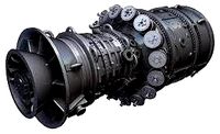
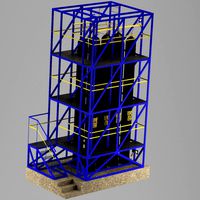
COMPRESSION LOADED CERAMIC TURBINE DISC TECHNOLOGY.
by GrabCAD
Last crawled date: 1 year, 11 months ago
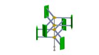
Pochari Technologies is reviving long-forgotten turbine engine technology. With advancements in single-crystal nickel alloys, turbine designers have been able to increase turbine inlet temperatures to record levels. The downside of this is the need to utilize large amounts of compressor bleed air, reducing engine efficiency. Conventional engineering ceramics including silicon nitride and carbide have been forgotten in part due to the focus on ceramic matrix composites. A relatively elegant and simple design is the use of a composite (carbon-fiber) hoop holding the centrifugal forces acting on the blade. Conventional engineering ceramics have uneven properties, rendering them unable to tolerate concentrated forces found in conventional mating conditions use in current turbine disc designs. Contrary to popular belief, silicon carbide has a tensile strength of 63,000 psi, sufficient to tolerate the tensile loads. The primary issue is the lack of uniformity, low flexural strength, and high brittleness. The simple (in hindsight obvious), the solution is to load the blades purely in compression strength (where ceramics thrive), to take advantage of the high-temperature capacity of these materials. Turbine inlet temperatures approaching 3000 F are feasible with silicon carbide. The blades transfer compression loads to hoop loads. The carbon fiber parameter containment hoop is not exposed to high gas temperatures. With this technology, it is possible to design small-scale sub-500 hp turboshafts with the efficiency of diesel engines (40%+), enabling jet-pack propulsion with 1 hour plus range.
“Ceramic materials offer a great potential for high-temperature application. This,
however, means it is necessary to live – even in future – with a brittle material with
small critical crack length and high crack growth velocity. Thus it will not be easy to
ensure reliability for highly loaded ceramic components, keeping in mind that for
reaction bonded ceramics the material inherent porosity is in the same order of
magnitude as the critical crack length. A solution to increase the reliability of ceramic
turbines may be a compression loaded rotor design with fiber reinforced hooping”
R. Kochendrfer 1980
“A vaned rotor of the type comprising a central metal hub or rotor body carrying a plurality of rotor blades made of a ceramic material, in which the blades are simply located on the rotor body and held in place by a coil of carbon fibres or ceramic fibres which surrounds the blades. To form a support surface for the coil each blade has a transverse part at the radially outer end thereof, which is partly cylindrical and which together with the transverse parts of the other blades, forms a substantially cylindrical support surface for the coil. Although ceramic materials used for such vanes (silicon nitride, silicon carbide, alumina, etc.) have much better physical properties at high temperatures (i.e., over l,lC than any metal alloy, especially if undergoing compression loads, they are nevertheless very difficult to couple to metal parts because of their relative fragility, lack of ductility, and their low coefficient of expansion.Because of the lack of ductility of ceramic materials, the driving forces exerted during operation of the rotor give rise to a concentration of the load in parts of the coupling areas between the ceramic vanes and the metal body of the rotor. This frequently causes breakages in these parts. The various systems presently in use for attaching a ceramic blade by the root to a metal rotor body for a gas turbine are generally inadequate because these systems, including dovetail fixings having both straight and curved sides, do not take sufficient account of the rigidity and relative fragility of the ceramic vanes.This problem is exacerbated by the fact that present manufacturing techniques for ceramic materials are still not able to provide a complete homogeneity of composition and structure of the material, so that adjacent areas of ceramic material can vary by up to 200% in tensile strength. For this reason the known types of coupling between a support disc forming a rotor body and rotor vanes of ceramic material, which rely on a wedging action, are not satisfactory”
R Cerrato Fiat SpA, U.S patent 3857650A, 1973
“A Compression Structured Ceramic Turbine looks feasible. A new engine aerodynamic cycle with effective working fins to off set windage loss, a reduced tip speed to enhance aeromechanics and
the possible utilization of leakage gas to augment thrust should be considered. Also, the prospect for more efficient energy extraction offered by inverted taper in the span of the turbine blade should be of prime interest to turbine designers in any future engine utilizing a Compression Structured Ceramic Turbine. Material property data and design refinements based on this data will also have to be seriously considered”
“The “Novel” feature of this ceramic turbine rotor design involves maintaining the ceramic
rotating components in astate of compression at all operating conditions. Many ceramic materials being considered for gas turbine components today display compressive strengths ranging from three to eight times their tensile strengths. Utilizing the high compressive strengths of ceramics in gas turbines for improving ceramic turbine structural integrity has interested engineers in recent years as evidenced by a number of patents and reports issued on Compression Structured Ceramic Turbines with one as early as 1968. Turbine blades designed to be in compression could greatly enhance the reliability of the ceramic hot section components. A design of this nature was accomplished in this contractual effort by using an air-cooled, high strength, lightweight rotating composite containment hoop at the outer diameter of the ceramic turbine tip cooling fins which in turn support the ceramic turbine blades in compression against the turbine wheel. A brief description of the detailed structural and thermal analysis and projected comparable performance between the Compression Structured Ceramic Turbine”.
P.J Coty, 1983
Similar models
grabcad
free

jet Turbine
...ials such as nickel alloys or titanium alloys that can withstand the high temperatures and stresses of the operating environment.
grabcad
free

turbine blades design
...gh temperature, high pressure gas produced by the combustor. the turbine blades are often the limiting component of gas turbines.
grabcad
free

Turbine blade
...urbine. the blades are responsible for extracting energy from the high temperature, high pressure gas produced by the combustion.
grabcad
free

Gas Turbine Engine
...gas turbine engine
grabcad
a model of a gas turbine including a fan, rotor and stator blades and a shaft
grabcad
free

Turbine blade
... wheel or rotor, typically fitted with vanes, is made to revolve by a fast-moving flow of water, steam, gas, air, or other fluid.
grabcad
free

Core engine assembly for CFM56
...nd rotor blades which represent the high pressure compressor (hpc),combustion chamber assembly,1 stage of high pressure turbine.
3dwarehouse
free

Airplane Jet Engine Fan {130Kb}
...r cooling, and thermal barrier coatings. #aircraft #airplane #blade #blades #engine #fan #jet #prop #proppeller #turbine #turning
3d_export
$100
turbine a gaz 9fa general electrique
... in the static analysis only the vane part is shown when examining the results. more information my email m.siaghi@esti-annaba.dz
grabcad
free

Blade
...blade
grabcad
gas turbine compressor rotor blade
grabcad
free

Jet engine
...igh speed and compress or squeeze the air. the compressed air is then sprayed with fuel and an electric spark lights the mixture.
Compression
turbosquid
$20
compresser
... available on turbo squid, the world's leading provider of digital 3d models for visualization, films, television, and games.
turbosquid
$4

Compression Tap
...for download as blend, gltf, obj, stl, dae, fbx, wrl, and usd on turbosquid: 3d models for games, architecture, videos. (1650763)
turbosquid
$7
Compression reducing tee
...ty free 3d model compression reducing tee for download as max on turbosquid: 3d models for games, architecture, videos. (1540313)
3d_export
$5

Mustang Compressed blend
...mustang compressed blend
3dexport
turbosquid
$19
Compression hips trainer
... compression hips trainer for download as , fbx, stl, and obj on turbosquid: 3d models for games, architecture, videos. (1684685)
turbosquid
$10
Compressed air station
...compressed air station for download as max, 3ds, fbx, and obj on turbosquid: 3d models for games, architecture, videos. (1598414)
turbosquid
$35

Compressed-air Engine
... available on turbo squid, the world's leading provider of digital 3d models for visualization, films, television, and games.
turbosquid
$19

Concrete Compression Tester
... available on turbo squid, the world's leading provider of digital 3d models for visualization, films, television, and games.
turbosquid
$4

Compression TAP worn
...for download as blend, usd, dae, gltf, fbx, obj, stl, and wrl on turbosquid: 3d models for games, architecture, videos. (1652641)
turbosquid
$49

Compressed Gas Cylinder and Regulator
...odel compressed gas cylinder and regulator for download as ma on turbosquid: 3d models for games, architecture, videos. (1170670)
Disc
archibase_planet
free

Discs
...discs
archibase planet
compact discs cd compact disk
discs - 3d model (*.gsm+*.3ds) for interior 3d visualization.
turbosquid
$7
SS with Disc Bonbon with disc
...ee 3d model ss with disc bonbon with disc for download as max on turbosquid: 3d models for games, architecture, videos. (1285181)
3d_export
$20
Car discs
...car discs
3dexport
car discs
3d_export
$5

disc knob
...disc knob
3dexport
disc knob
3d_export
$5
disc knob
...disc knob
3dexport
disc knob
3d_ocean
$2

Compact Disc
...compact disc
3docean
album audio cd compact disc dvd laser disc movie music
a cd
turbosquid
$30

Protrusion and slipped disc herniated disc
...usion and slipped disc (herniated disc) for download as blend on turbosquid: 3d models for games, architecture, videos. (1572177)
turbosquid
free
disc
... available on turbo squid, the world's leading provider of digital 3d models for visualization, films, television, and games.
3d_ocean
$5

Realistic Floppy Disc
...op storage usb
this is a model of a floppy disc. floppy discs were used as computer storage devices before the invention of usbs.
3d_export
$10

brake-disc-brembo
...brake-disc-brembo
3dexport
brake-disc-brembo
Turbine
3d_export
$5

turbine
...turbine
3dexport
it is a turbine to use it in some spaceship
3d_export
$5

turbine
...turbine
3dexport
turbine, with animation included, more texture of it
3d_ocean
$4

Wind Turbine
...n
and render setup turbine wind
wind turbine, modeled with cinema4d r13 , render setup and textured, custom logo for wind turbine
turbosquid
$1

Turbine
...turbosquid
royalty free 3d model turbine for download as ige on turbosquid: 3d models for games, architecture, videos. (1385242)
3d_export
$40
wind turbine
...wind turbine
3dexport
wind turbine
3d_export
$40

wind turbine
...wind turbine
3dexport
wind turbine
3d_export
$40
wind turbine
...wind turbine
3dexport
wind turbine
3d_export
$40
wind turbine
...wind turbine
3dexport
wind turbine
3d_export
$40
wind turbine
...wind turbine
3dexport
wind turbine
3d_export
$40
wind turbine
...wind turbine
3dexport
wind turbine
Ceramic
design_connected
$16

Ceramics
...ceramics
designconnected
piet hein eek ceramics computer generated 3d model. designed by eek, piet hein.
turbosquid
$1

ceramic
...turbosquid
royalty free 3d model ceramic for download as max on turbosquid: 3d models for games, architecture, videos. (1651807)
turbosquid
$3
Ceramics
... model ceramics for download as 3ds, obj, fbx, blend, and dae on turbosquid: 3d models for games, architecture, videos. (1453821)
turbosquid
free

Ceramic
... available on turbo squid, the world's leading provider of digital 3d models for visualization, films, television, and games.
design_connected
$9
Ceramic Cups
...ceramic cups
designconnected
ceramic cups computer generated 3d model.
3ddd
$1
Унитаз Art Ceram
...унитаз art ceram
3ddd
art ceram
унитаз art ceram
design_connected
$11

Ceramic Clocks
...ceramic clocks
designconnected
vitra ceramic clocks computer generated 3d model. designed by nelson, george.
design_connected
$20

Cartoccio Ceramics
...cartoccio ceramics
designconnected
paola paronetto cartoccio ceramics computer generated 3d model. designed by paronetto, paola.
3d_ocean
$2

Ceramic Vase
...ls — polygons / vertices): — vase — ceramic — 13.920 / 13.920 model was made in autodesk 3ds max 2014 and prepared to render i...
3d_ocean
$2

Ceramic
...ceramic
3docean
this is textures for bathroom format include : .c4d .3ds .obj .png
Loaded
3ddd
$1
Billiani Load
...billiani load
3ddd
billiani , load
стулья load итальянской фабрики load
turbosquid
$5

Wheelbarrow loaded
...id
royalty free 3d model wheelbarrow loaded for download as on turbosquid: 3d models for games, architecture, videos. (1615308)
turbosquid
$15
Dummy Load
...odel dummy load for download as 3ds, obj, fbx, blend, and dae on turbosquid: 3d models for games, architecture, videos. (1363932)
turbosquid
$3

Load-limitroadsign
...oad-limitroadsign for download as 3ds, dae, fbx, obj, and stl on turbosquid: 3d models for games, architecture, videos. (1532902)
3d_export
$79

iveco daily loading
...iveco daily loading
3dexport
iveco daily loading 3d model. include max, obj, fbx files.
3d_export
$9

automatic loading and unloading punch
...automatic loading and unloading punch
3dexport
automatic loading and unloading punch
3d_export
$19
concrete loading ramp
...te loading ramp
3dexport
concrete loading ramp 3d model. real-time ready, multiple import formats<br>thank you for reading
turbosquid
$1
Front Load Dumpster
...free 3d model front load dumpster for download as obj and fbx on turbosquid: 3d models for games, architecture, videos. (1694510)
turbosquid
$45
AGV to Container Load
... model agv to container load for download as ma, obj, and fbx on turbosquid: 3d models for games, architecture, videos. (1589627)
turbosquid
$20

Pelican Loading Center
... available on turbo squid, the world's leading provider of digital 3d models for visualization, films, television, and games.
Technology
turbosquid
$3

Technology
... available on turbo squid, the world's leading provider of digital 3d models for visualization, films, television, and games.
turbosquid
free

technological robot
...urbosquid
free 3d model technological robot for download as on turbosquid: 3d models for games, architecture, videos. (1327354)
turbosquid
$35

Technology Robot
...ty free 3d model technology robot for download as obj and fbx on turbosquid: 3d models for games, architecture, videos. (1160448)
3d_export
$25

Steampunk technology
...f science fiction that incorporates technology and aesthetic designs inspired by 19th-century industrial steam-powered machinery.
3ddd
$1

Concept Technology
...concept technology
3ddd
концепт уборочной техники.
3ds max design 2009
3d_ocean
$30

Technology Mascot
...tup technology
cinema 4d r14 file format global illimunation render setup metalic materials hdri light settings high detail model
3d_export
$12
Wheels of old Soviet technology
...wheels of old soviet technology
3dexport
wheels of old soviet technology for 3d printing
turbosquid
$49

Technologic Accessories Set
...model technologic accessories set for download as max and obj on turbosquid: 3d models for games, architecture, videos. (1452166)
3d_export
free
technology complex building
...technology complex building
3dexport
headquarters for a tech firm company modeled in revit 2018
turbosquid
$79

Ancient Technology Megalithic Structure
...l ancient technology megalithic structure for download as c4d on turbosquid: 3d models for games, architecture, videos. (1389200)