Thingiverse
Coax Dipole Antenna Enclosure by ka9etc
by Thingiverse
Last crawled date: 4 years, 8 months ago
TinyGS Coax Dipole Antenna Enclosure
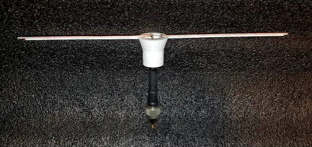
This is a 3D printed support structure for a 50 ohm coax dipole antenna with dimensions to support operation in the 70cm band. There is a TinyGS logo on the front. Antenna construction used is an excellent coax dipole design from Judhi (note: this TinyGS Coax Dipole Antenna Enclosure is not required for successful coax dipole operation).
The .stl file name indicates the following antenna dimensions and attributes:
(driven_element_coax)_(feed_coax)_(diameter_in_mm_of_feed_coax)_(front_or_back_half).stl
So, for example, RG316_RG6_7.00_front.stl indicates:
The driven element is RG316 coax cable.
The feed is RG6 coax.
The diameter of the feed channel is 7.00mm within the vertical part of the 3D print.
The .stl file is for the front half of the 3D print containing the TinyGS logo (the back half does not have the logo).
Assembly instructions:
Construct the coax dipole using your preference of feed coax from one of the supported coax types herein. Reference the file coax_dipole_dimensions.jpg herein. The coax dipole antenna design used and shown is provided by Judhi.
3D print the the front and back half of the two .stl files corresponding to the feed coax selected. Make sure to orient the .stl in your slicer as shown in coax_dipole_stl_print_orientation.jpg. The driven element is always RG316 coax. More coax types for the driven element will be supported in the future.
Use the two guide-pin holes in the front and back 3D printed structures to insert ~2mm diameter toothpicks during assembly.
Apply adhesive to the front and back half vertical planar surfaces. Sandwich the feed portion of the coax dipole in between the front and back half 3D printed structures leaving the toothpicks in as guide pins. For adhesive, foam-tac, epoxy, or cyroacrylinate all work well. Clamp the front and back halves together until the adhesive has cured.
Trim the U-shaped horizontal channel ends as needed to be flush with or a little in from the ends of the RG316 coax driven element.
Apply adhesive to the horizontal U-shaped channel and press-fit the RG316 coax into the channel. Wait for adhesive to cure.
Weatherproofing: fill in the cone-shaped cavity at the top with hot glue to seal that area and coax feed leads from the elements and prevent water from accumulating and shorting the leads from the feed coax.
Your TinyGS coax dipole antenna is now ready to use. Packet decodes of over 1700km from a 7W satellite transmission using the TinyGS ground station software have been received using the exact configuration herein.
Purpose of this design
This design provides an alternative to a PVC pipe enclosure or similar when installing a coax dipole outdoors. The structure keeps the coax driven element more stationary in wind, rain, and snow, and the hot glue applied in step #7 above keeps the coax feed leads protected from the elements.
Getting started
It's very easy and inexpensive to get started in the exciting world of receiving CubeSat satellite transmissions using TinyGS.
See: https://tinygs.com/
"TinyGS is an open network of Ground Stations distributed around the world to receive and operate LoRa satellites, weather probes and other flying objects, using cheap and versatile modules."
Credits:
TinyGS ground station software provided by: https://github.com/G4lile0/tinyGS , https://github.com/4m1g0 , https://github.com/gmag11
The coax dipole dimensions are courtesy of: https://twitter.com/judhi, see: JP Coax antenna https://twitter.com/judhi/status/1364564083845058566.
Disclaimer:
KA9ETC, the designer of this antenna enclosure, has no affiliation with TinyGS and makes no guarantees of performance, but highly recommends trying TinyGS as one of the over 1,400+ users of TinyGS! Your results may vary.