Thingiverse
CNC3018 spindle mount
by Thingiverse
Last crawled date: 4 years, 3 months ago
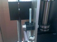
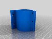
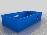
The original spindle holder was introducing a lot of runout and wobbling. My goal was to use this CNC3018 for PCB milling and I needed a decent precision for it so I decided to redesign the spindle holder and Z-axis sledge.
Before you print
Check your CNC3018-like machine if it fits this design. I know there
are many variations of this machine with LMUU10 bearings on Z-axis instead LMUU08 and different bearings spacing. In this project the spacing between linear bearings center is 38mm which kinda explains why the trapeizodal screw has to be cut in order to fit in between.
Required items:
2x LM08LUU linear bearings (45mm long)
1x Trapezoidal screw TR8x4 (check with your machine) with anti-backlash nut (needs to be cut and grinded to fit inside the Z-axis sledge)
3x Hex M6 screw, nut and washer
AC glue
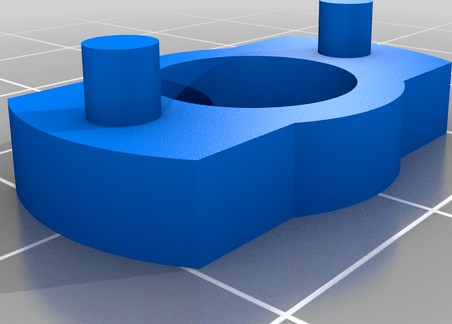
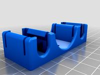
You need to fix the trapezoidal screw with the spring and antibacklash-nut inside the sledge. Then check it with the trapeizodal rod if it fits properly, mechanical alignment and so on. Put the the small lid (z_axis_locker.stl) on the trapeizodal screw opening and fix it with glue with the sledge. Make sure, the glue did not get to the screw thread.
Same thing for the linear berrings - apply the glue on the inner walls of the linear bearing holes and push the bearings inside, make sure to align the bearings equally from both sides of the slege. Wait for the glue to dry.
With this design I was able to mill PCB's with accurate-enough precision for my DIY projects.
You can see example video and photos of the PCB making process here:
https://www.youtube.com/watch?v=OzJ_bb20_9I
https://photos.app.goo.gl/vLs5gWqZPQQpVirQ8
Any creative comments and questions are welcome.
Before you print
Check your CNC3018-like machine if it fits this design. I know there
are many variations of this machine with LMUU10 bearings on Z-axis instead LMUU08 and different bearings spacing. In this project the spacing between linear bearings center is 38mm which kinda explains why the trapeizodal screw has to be cut in order to fit in between.
Required items:
2x LM08LUU linear bearings (45mm long)
1x Trapezoidal screw TR8x4 (check with your machine) with anti-backlash nut (needs to be cut and grinded to fit inside the Z-axis sledge)
3x Hex M6 screw, nut and washer
AC glue
You need to fix the trapezoidal screw with the spring and antibacklash-nut inside the sledge. Then check it with the trapeizodal rod if it fits properly, mechanical alignment and so on. Put the the small lid (z_axis_locker.stl) on the trapeizodal screw opening and fix it with glue with the sledge. Make sure, the glue did not get to the screw thread.
Same thing for the linear berrings - apply the glue on the inner walls of the linear bearing holes and push the bearings inside, make sure to align the bearings equally from both sides of the slege. Wait for the glue to dry.
With this design I was able to mill PCB's with accurate-enough precision for my DIY projects.
You can see example video and photos of the PCB making process here:
https://www.youtube.com/watch?v=OzJ_bb20_9I
https://photos.app.goo.gl/vLs5gWqZPQQpVirQ8
Any creative comments and questions are welcome.
Similar models
grabcad
free

linear ball bearing screw
...abcad
this is an alternative to a ball screw spindle. the spindle is a standard trapezoid thread spindle.
the nut is transparent
thingiverse
free
K8200 trapezoidal spindle set 8x1.5mm by verleihnix
... flexible motor coupling, 2 nuts (steel), 0.5m spindle, one nut (rg7),a few m5 nuts and screws.
no need for drilling, milling ...
thingiverse
free

K8200 / 3Drag left z axis bearing alignment block by RobinSt
... clips are needed. should the bearing be (a little) loose, wrap it with a little glue tape (or drop of glue) to make it fit snug.
thingiverse
free
Z-Axis Lead Screw Nut Linear Bearing Mount by virtualight
...lead screw nut linear bearing mount by virtualight
thingiverse
prototype z-axis lead screw nut linear bearing mount for rigidbot
thingiverse
free

CNC 3018 spindle/laser holder
...ppy with your own machine.
you may need to glue or add some scotch tape around the bearings to fix them, and the rest will be ok.
thingiverse
free

End switch Z axis by krism4a1
...the z axis end switch.
it works great, it can be adjusted with unprecedented precision.
need an old micrometer, screws m4 + t nut
thingiverse
free

Z-axis spindle aligner for Ender 3 by alfmagan
...alfmagan thingiverse z-axis spindle aligner for ender 3 and similar mod for z-axis spindle plumbing. attached stl files of...
thingiverse
free

Z-axis stabilisation by roland124
...ling anything on the printer . you just need some 3mm screws and nuts . it is screwed between the spindle and the bearing guide .
thingiverse
free
3018 CNC mounting hardware for 100mm metal Z axis
...ndle motors. if your 42mm spindle has a collar in the middle, the clamp will be very tight and you may want to scale it up a bit.
thingiverse
free

3018 pro Z axis 500w 55mm Spindle Upgrade
... mount on the x axis.
the new support allows the z axis to rise 10mm higher than the original support.
i hope it could help you !
Cnc3018
thingiverse
free
CNC3018 Offline Controller Box
...cnc3018 offline controller box
thingiverse
cnc3018 offline controller box
thingiverse
free

Chain for cnc3018 by IuriiKashitsin
...chain for cnc3018 by iuriikashitsin
thingiverse
chain
thingiverse
free

CNC3018 500w spindle mount by damian5602
...cnc3018 500w spindle mount by damian5602
thingiverse
500w spindle mount for cnc3018
thingiverse
free

Aspiration for CNC3018 by cmaiche
... result which suits me and which avoids having too much plastic shavings.
of course, do not forget to turn on the vacuum cleaner.
thingiverse
free

Cage nut for CNC3018 by MeKam
... for cnc3018 by mekam
thingiverse
cage nut for the table using the hexagon head screws provided with the chinese cnc 3018 model.
thingiverse
free

Cône Air Assist CNC3018 by grispoils
...ir assist cnc3018 by grispoils
thingiverse
https://fr.aliexpress.com/item/32964674684.html?spm=a2g0s.9042311.0.0.12756c376urprt
thingiverse
free

CNC3018 vacuum duct by Wierdd
... by wierdd
thingiverse
can be used with this https://www.thingiverse.com/thing:4830943
use hose purton sl eco 38mm (1 1/2")
thingiverse
free

Clamp modification for CNC3018 by skippergeoff
...adjusting screw cap for the clamps supplied with most 3018pro engraving machines.
these make adjustment of the clamps much easier
thingiverse
free

Baseplate for spindle clamp (52/55mm), CNC3018/CNC3018 Pro
...sher
4x m6 spring ring
optional:
4x m2x14mm (allen) screw
2x micro switch (print)
1x anti backlash nut
2x 5x56mm rod
2x linelaser
thingiverse
free

CNC3018 Pro: cover for 40x20mm fan by adamlaurie
...0mm fan by adamlaurie
thingiverse
expanded original to fit 20mm instead of 10mm deep fan. bigger fan means even quieter running.
Spindle
3d_export
$5
simple spindle
...simple spindle
3dexport
simple spindle
design_connected
$7

Spindle shade
...spindle shade
designconnected
rothschild&bickers spindle shade computer generated 3d model.
design_connected
$9

Spindle Table
...spindle table
designconnected
ligne roset spindle table computer generated 3d model. designed by ascalon, brad.
design_connected
free

Spindle Clock
...spindle clock
designconnected
vitra spindle clock free models computer generated 3d model. designed by george nelson.
turbosquid
$10

Spindle Table
... available on turbo squid, the world's leading provider of digital 3d models for visualization, films, television, and games.
turbosquid
$9

Spindle-chair
... available on turbo squid, the world's leading provider of digital 3d models for visualization, films, television, and games.
turbosquid
$9

DVD Spindle
... available on turbo squid, the world's leading provider of digital 3d models for visualization, films, television, and games.
3d_export
$15

Spike Spindle 3D Model
...s procession spindled spindling spiking spearing spear document bill hole paperwork
spike spindle 3d model firdz3d 90192 3dexport
turbosquid
$15

Nelson Spindle Clock
... available on turbo squid, the world's leading provider of digital 3d models for visualization, films, television, and games.
turbosquid
$2

Vitra Spindle Clock
... available on turbo squid, the world's leading provider of digital 3d models for visualization, films, television, and games.
Mount
3d_export
free

mounting bracket
...mounting plate is the portion of a hinge that attaches to the wood. mounting plates can be used indoors, cabinetry and furniture.
turbosquid
$2

MOUNTING
... available on turbo squid, the world's leading provider of digital 3d models for visualization, films, television, and games.
turbosquid
free

Mounts
... available on turbo squid, the world's leading provider of digital 3d models for visualization, films, television, and games.
turbosquid
free

Mount Fuji
...fuji
turbosquid
free 3d model mount fuji for download as obj on turbosquid: 3d models for games, architecture, videos. (1579977)
3d_export
$5

Headphone mount LR
...headphone mount lr
3dexport
headphone mount l+r
turbosquid
$39

Mount rainier
...quid
royalty free 3d model mount rainier for download as fbx on turbosquid: 3d models for games, architecture, videos. (1492586)
turbosquid
$5

pipe mounting
...quid
royalty free 3d model pipe mounting for download as obj on turbosquid: 3d models for games, architecture, videos. (1293744)
turbosquid
$3

Mounting Tires
...uid
royalty free 3d model mounting tires for download as fbx on turbosquid: 3d models for games, architecture, videos. (1708511)
3d_export
$5

Magnetic GoPro Mount
...pro mount
3dexport
cool magnetic mount for gopro. allows you to mount the camera on flat metal surfaces and get exclusive shots.
turbosquid
$5

Stone Mount
...ty free 3d model stone mount for download as ma, obj, and fbx on turbosquid: 3d models for games, architecture, videos. (1370306)