Thingiverse
CNC frame rock tumbler by loska
by Thingiverse
Last crawled date: 3 years ago
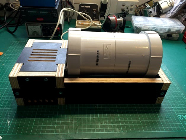
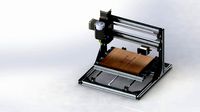
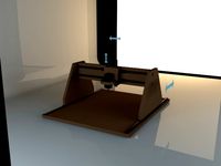
Heavy duty rock tumbler / barrel rumbler
Polish rocks or metal 3D printed parts!
This design uses a mains powered AC synchronous geared motor which runs quietly and reliably for long durations.
The barrel is made from cheap, durable PVC plumbing components and can be optionally lined with rubber or a printed insert. Mine is lined with checkerplate rubber sheet.
Note that I am in Australia. Barrel parts are available from Bunnings 'Holman' brand. Electrical parts from Jaycar. The motor and rubber mounts are from eBay and the O-rings came from a kit from Aldi.
Bill of materials
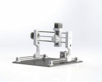
Frame
6 parts, CNC cut from 18mm plywood
Cover plate, from thin acrylic / aluminium etc (I used 2mm clear acrylic).
10 x 10G x 30mm wood screws
4 x small self tapping screws approx 3mm x 10mm long for cover plate
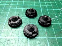
Printed parts:
4 x drive wheels
1 x motor pulley
2 x shaft pulleys
plug to cover motor shaft hole
(STL is included with all parts for printing)
Hardware - barrel:
2 x 100mm PVC threaded access coupling (105mm long overall)
2 x 100mm PVC screw on cap
Short length of 100mm PVC pipe
PVC glue / primer
Hardware - mechanism:
Motor - AC Synchronous geared 100RPM 60mm x 60mm
4 x M4 15mm x 15mm rubber mounts, Male - Female threads
4 x M4 x 25mm machine screws
4 x M4 nyloc nuts and washers
1 x M3 grub screw + nut (for motor pulley)
2 x 300mm lengths of M8 threaded rod
20 x M8 nuts, 13mm hex (I used 8 x nylocs and 12 x plain nuts)
4 x 608ZZ (skateboard) bearings
2 x O-rings 50mm ID x 3.55mm for drive bands
4 x O-rings 28mm ID x 3.55mm for drive wheel tyres
Hardware - electrical:
IEC power socket + fuse + switch (optional)
Mains power cable
Wire, lugs, solder, heatshrink etc.
Instructions
Barrel
Measure the distance inside the threaded access coupling up to the ridge, from the non-threaded end.
Cut a length of 100mm PVC pipe just shorter than twice this distance.
Assemble the 2 couplings to each other with the pipe, using PVC glue (primer optional).
Screw on the end caps.
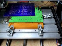
Frame
Cut all 6 parts from 18mm Plywood
Contersink screw holes if preferred
Assemble frame with screws
Rout a rebate around the inside of the underneath of the motor box, to fit the cover plate. I used a 9.5mm rebate bit, 30mm diameter, 5mm deep using a hand router.
It is easier to take the outer ends and lid back off the frame for the remainder of the assembly.
Notes:
All cuts can be made with a 6mm tool except for the 4 x motor mount holes which are 4mm diameter.
Outer pockets for 608 bearings are 7mm deep
Outer pocket for IEC power socket + fuse + switch is 16.5~17mm deep, allowing the clips to hold on the thin ridge left.
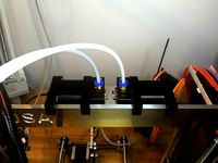
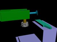
Mechanism
Press M8 nuts (preferably nylocs) into the drive wheels and shaft pulleys.
Press 608 bearings into the outer end frame and inner end frame.
Push the motor shaft plug into the inner end frame.
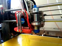
Thread drive wheels, lock nuts and bearing nuts onto the shafts (see photos).
Insert shafts through the bearings in the inner frame end.
Fit the outer end frame with the shafts poking through the bearings.
Fit M8 nuts (preferably nylocs) to the outer end of the shafts.
Fit M8 plain nuts to the inner ends of the shafts, plus an extra plain nut to lock the shaft pulleys.
Adjust the position of the drive wheels so that the barrel fits properly.
Fit the shaft pulleys onto the shafts.
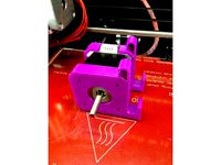
Fit the motor pulley to the motor with the grub screw and M3 nut. Note the boss goes towards the outside end of the shaft.
Attach the 4 x rubber mounts to the frame with M4 x 25 screws.
Loosely place the drive bands and fit the motor to the rubber mounts with washers and nyloc nuts.
Adjust the shaft pulleys to align to the motor pulley.
Tighthen all lock nuts.
Wiring
NOTE: This design uses mains voltage, which is dangerous! It may be illegal in your country to wire this yourself. Do not attempt to wire this unless you know what you are doing!
The motor has 3 terminals. The middle terminal is Neutral and the outer terminals are each active, for a different rotation direction. Connect the active to only 1 of the outer terminals and leave the other one unconnected.
If you are using a metal cover plate, it is a good idea to connect the Earth wire to it. Otherwise, connect Earth to the motor housing via one of the mounting screws.
Fit the rest of the frame plus the cover plate with 4 x small self tapping screws before operating.
Polish rocks or metal 3D printed parts!
This design uses a mains powered AC synchronous geared motor which runs quietly and reliably for long durations.
The barrel is made from cheap, durable PVC plumbing components and can be optionally lined with rubber or a printed insert. Mine is lined with checkerplate rubber sheet.
Note that I am in Australia. Barrel parts are available from Bunnings 'Holman' brand. Electrical parts from Jaycar. The motor and rubber mounts are from eBay and the O-rings came from a kit from Aldi.
Bill of materials
Frame
6 parts, CNC cut from 18mm plywood
Cover plate, from thin acrylic / aluminium etc (I used 2mm clear acrylic).
10 x 10G x 30mm wood screws
4 x small self tapping screws approx 3mm x 10mm long for cover plate
Printed parts:
4 x drive wheels
1 x motor pulley
2 x shaft pulleys
plug to cover motor shaft hole
(STL is included with all parts for printing)
Hardware - barrel:
2 x 100mm PVC threaded access coupling (105mm long overall)
2 x 100mm PVC screw on cap
Short length of 100mm PVC pipe
PVC glue / primer
Hardware - mechanism:
Motor - AC Synchronous geared 100RPM 60mm x 60mm
4 x M4 15mm x 15mm rubber mounts, Male - Female threads
4 x M4 x 25mm machine screws
4 x M4 nyloc nuts and washers
1 x M3 grub screw + nut (for motor pulley)
2 x 300mm lengths of M8 threaded rod
20 x M8 nuts, 13mm hex (I used 8 x nylocs and 12 x plain nuts)
4 x 608ZZ (skateboard) bearings
2 x O-rings 50mm ID x 3.55mm for drive bands
4 x O-rings 28mm ID x 3.55mm for drive wheel tyres
Hardware - electrical:
IEC power socket + fuse + switch (optional)
Mains power cable
Wire, lugs, solder, heatshrink etc.
Instructions
Barrel
Measure the distance inside the threaded access coupling up to the ridge, from the non-threaded end.
Cut a length of 100mm PVC pipe just shorter than twice this distance.
Assemble the 2 couplings to each other with the pipe, using PVC glue (primer optional).
Screw on the end caps.
Frame
Cut all 6 parts from 18mm Plywood
Contersink screw holes if preferred
Assemble frame with screws
Rout a rebate around the inside of the underneath of the motor box, to fit the cover plate. I used a 9.5mm rebate bit, 30mm diameter, 5mm deep using a hand router.
It is easier to take the outer ends and lid back off the frame for the remainder of the assembly.
Notes:
All cuts can be made with a 6mm tool except for the 4 x motor mount holes which are 4mm diameter.
Outer pockets for 608 bearings are 7mm deep
Outer pocket for IEC power socket + fuse + switch is 16.5~17mm deep, allowing the clips to hold on the thin ridge left.
Mechanism
Press M8 nuts (preferably nylocs) into the drive wheels and shaft pulleys.
Press 608 bearings into the outer end frame and inner end frame.
Push the motor shaft plug into the inner end frame.
Thread drive wheels, lock nuts and bearing nuts onto the shafts (see photos).
Insert shafts through the bearings in the inner frame end.
Fit the outer end frame with the shafts poking through the bearings.
Fit M8 nuts (preferably nylocs) to the outer end of the shafts.
Fit M8 plain nuts to the inner ends of the shafts, plus an extra plain nut to lock the shaft pulleys.
Adjust the position of the drive wheels so that the barrel fits properly.
Fit the shaft pulleys onto the shafts.
Fit the motor pulley to the motor with the grub screw and M3 nut. Note the boss goes towards the outside end of the shaft.
Attach the 4 x rubber mounts to the frame with M4 x 25 screws.
Loosely place the drive bands and fit the motor to the rubber mounts with washers and nyloc nuts.
Adjust the shaft pulleys to align to the motor pulley.
Tighthen all lock nuts.
Wiring
NOTE: This design uses mains voltage, which is dangerous! It may be illegal in your country to wire this yourself. Do not attempt to wire this unless you know what you are doing!
The motor has 3 terminals. The middle terminal is Neutral and the outer terminals are each active, for a different rotation direction. Connect the active to only 1 of the outer terminals and leave the other one unconnected.
If you are using a metal cover plate, it is a good idea to connect the Earth wire to it. Otherwise, connect Earth to the motor housing via one of the mounting screws.
Fit the rest of the frame plus the cover plate with 4 x small self tapping screws before operating.
Similar models
thingiverse
free

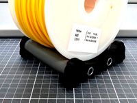
Wall-mount spool holder with quick release fastener by loco
...unk screws 4mm diameter
3x m8 nuts
1x m8 threaded rod
2x 608 ball bearing
1x m3x20 screw
1x m3 nut (nyloc nut or loctite)
thingiverse
free
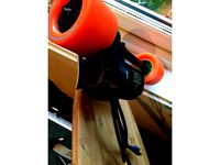
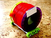
Filament Spool Roller by JamesRX
...bearing x 4 (or any bearing /w 8mm hole can fit inside the pvc pipe)
m8 screw rod x 2 (20mm longer than the pvc pipe)
m8 nut x8
grabcad
free

M8 Bolt with washer and Nyloc Nut
...m8 bolt with washer and nyloc nut
grabcad
m8 bolt with washer and nyloc nut
36mm full thread
stainless
thingiverse
free
Torqueboards V4 motor mount pulley cover by Mikaelj
...j
thingiverse
designed for torqueboards v4 mount for covering belt pulley. fits tb 6374 motor without cutting down shaft length.
thingiverse
free
Hypercube Evolution Y axis Euro frame (Y10 / Y12) by PaulArnold
...ews
done
edit 15.06.2019:
i uploaded a y12 version upon request.
however, this version is untested as i dont have 12mm rods on y.
3dwarehouse
free
M6 Cap Screw & Nyloc Nut
... m6 nyloc nut, both with correct helical threads #bolt #helical #helix #hex #m6 #nut #nyloc #nylock #nylok #screw #spiral #thread
thingiverse
free

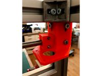
Anet A8 Z Axis CHUNK Reinforcement Top Mount & Z Motor Mount by TheWalkletts
...e job once the parts are printed.
top mounts take 1 x 608zz bearing each
join the two top mounts using m8 threaded rod & nuts
thingiverse
free
Tronxy X5SA tripple leadscrew upgrade by bunjatec
...en side plate it should be eliminated it's also a little low requiring the belt pulley to be mounted quite high on the shaft.
thingiverse
free

Nema17 peristaltic pump by Cristian2281
...mp and pin. rollers to be printed if not using mr105zz bearings.
this is still a work in progress and should be treated as such.
thingiverse
free
Ball bearing spool holder by bundyr
...ool holder
bom:
4pcs ball bearing 608
4pcs m8 washer
2pcs m8 nyloc nut
2pcs m8 hex nut
2pcs aluminium pipe
2pcs m8 threaded rod
Loska
thingiverse
free
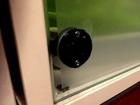
Replacement hinge plate for Ikea glass door cabinet by loska
...everal of these over the years and they work well.
note that the original silver cover cap push fits over this part, as pictured.
thingiverse
free
Bowden extruder hanger for 6mm frame by loska
...pper wires and keep things neat.
the files here are for a left hand extruder; simply flip along the x axis for a right hand set.
thingiverse
free
Beyblade ball bearing performance tip by loska
...o included, to adapt for other clearances or ball sizes. this file also includes the 3 other tip designs from the remixed design.
thingiverse
free

A4 Mini Vacuum Table by loska
...mounting points are set at 160mm spacing to suit my t-slot table. adjust as needed.
ideally, lightly skim the bed after mounting.
thingiverse
free
Air powered bottle water pistol by loska
...with the tubing.
fill the bottle 2/3 with water, screw in tight, pump up through the tyre valve to about 60psi and get squirting!
thingiverse
free
PCB milling alignment pin grid for 3018 CNC
...pins should be used for alignment. many thanks to loska and kudos for his awesome...
thingiverse
free

Nantendo LED matrix console game by loska
...ut attach the holder with double sided foam tape. note you may wish to file the solder pads and m2 screws to make this fit flush.
thingiverse
free
Aluminium Prusa i3 X-Carriage for Chimera and 18mm Sensor by loska
... screw holes in the chimera body through to the front, so i can adjust the nozzle heights easily by just taking the 30mm fan off.
thingiverse
free
Bowden extruder hanger for 8mm frame by Wast3D
...hanger for 8mm frame by wast3d thingiverse i remixed loska#39;s version of the motor hanger for a 6mm frame...
Tumbler
archibase_planet
free

Tumbler
...tumbler
archibase planet
tumbler
tumbler - 3d model (*.gsm+*.3ds) for interior 3d visualization.
3d_ocean
$65

TUMBLER
...tumbler
3docean
3d 3d beautiful car full detailed high poly tumbler
full detailed 3d model of the “tumbler”. ready for render!
turbosquid
$1

Tumbler A
...free 3d model ceramic tumbler a for download as fbx and blend on turbosquid: 3d models for games, architecture, videos. (1193044)
turbosquid
$1

Tumbler
...y free 3d model ceramic tumbler for download as fbx and blend on turbosquid: 3d models for games, architecture, videos. (1192366)
turbosquid
$15

Tumbler A
...free 3d model tumbler a for download as ma, max, obj, and fbx on turbosquid: 3d models for games, architecture, videos. (1298726)
turbosquid
$3

tumbler
... available on turbo squid, the world's leading provider of digital 3d models for visualization, films, television, and games.
turbosquid
$3

Tumbler
... available on turbo squid, the world's leading provider of digital 3d models for visualization, films, television, and games.
turbosquid
$1
tumbler
... available on turbo squid, the world's leading provider of digital 3d models for visualization, films, television, and games.
turbosquid
$1

tumbler
... available on turbo squid, the world's leading provider of digital 3d models for visualization, films, television, and games.
archive3d
free

Tumbler 3D Model
...ler 3d model
archive3d
tumbler
tumbler - 3d model (*.gsm+*.3ds) for interior 3d visualization.
Rock
3d_export
$5

Rock
...rock
3dexport
simple rock.
3d_export
$5
Rock
...rock
3dexport
20 rock
3d_ocean
$5
Rock
...rock
3docean
game ready low poly old stone rock
rock,low poly,
3d_export
$6
Rock
...rock
3dexport
rock 3d model
3d_ocean
$5
Rock
...rock
3docean
game rock low polygon old rock rock stone
2048*2048 texture. 90 polygon low poly. obj,blend,fbx , format
3d_ocean
$2

Rock
...rock
3docean
cliff crag organic rock stone
this is a rock 3d model. it works in horizontal and vertical position, too.
3ddd
$1

rock on
...rock on
3ddd
кресло качалка
кресло valdichenti rock on
3d_export
$5

the rock
...the rock
3dexport
the rock 3d model good quality for animation
design_connected
$27

On The Rocks
...on the rocks
designconnected
edra on the rocks computer generated 3d model. designed by binfaré, francesco.
design_connected
$13

Rock
...rock
designconnected
foscarini rock computer generated 3d model. designed by diesel creative team.
Cnc
3d_export
$35
Cnc
...cnc
3dexport
the cnc machine is unfinished
3d_export
$10
cnc router
...cnc router
3dexport
prototipe cnc router
3d_export
$10
cnc machine
...cnc machine
3dexport
cnc machine model with individual model files with assembly
3d_export
$5
Cnc 3D Model
...cnc 3d model
3dexport
cnc
cnc 3d model csiszar 61289 3dexport
turbosquid
$10

cnc bedroom
...osquid
royalty free 3d model cnc bedroom for download as max on turbosquid: 3d models for games, architecture, videos. (1494981)
turbosquid
$9
cnc(wood)
...rbosquid
royalty free 3d model cnc(wood) for download as max on turbosquid: 3d models for games, architecture, videos. (1189189)
turbosquid
$1

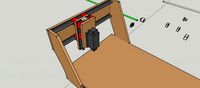
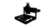
CNC Frame
...rbosquid
royalty free 3d model cnc frame for download as stl on turbosquid: 3d models for games, architecture, videos. (1371706)
turbosquid
free
cnc table
...rbosquid
royalty free 3d model cnc table for download as max on turbosquid: 3d models for games, architecture, videos. (1500926)
turbosquid
$30
CNC Lathe
...
royalty free 3d model cnc lathe for download as max and obj on turbosquid: 3d models for games, architecture, videos. (1284634)
turbosquid
$25
CNC Machine
...
royalty free 3d model cnc machine for download as ma and fbx on turbosquid: 3d models for games, architecture, videos. (1307199)
Frame
archibase_planet
free
Frame
...frame
archibase planet
frame photo frame
frame n190813 - 3d model (*.gsm+*.3ds) for interior 3d visualization.
archibase_planet
free
Frame
...frame
archibase planet
frame photo frame
frame n071113 - 3d model (*.gsm+*.3ds) for interior 3d visualization.
3ddd
$1

Frame
...frame
3ddd
frame
3ddd
free
Frame
...frame
3ddd
frame
archibase_planet
free

Frame
...frame
archibase planet
frame mirror frame ornament
frame n260113 - 3d model (*.gsm+*.3ds) for interior 3d visualization.
archibase_planet
free

Frame
...frame
archibase planet
frame photo frame
frame photo n190813 - 3d model (*.gsm+*.3ds) for interior 3d visualization.
archibase_planet
free
Frame
...frame
archibase planet
frame window window frame
frame 1 - 3d model (*.gsm+*.3ds) for interior 3d visualization.
archibase_planet
free
Frame
...frame
archibase planet
frame window frame window
frame 3 - 3d model (*.gsm+*.3ds) for interior 3d visualization.
archibase_planet
free
Frame
...frame
archibase planet
frame wall frame decoration
frame 1 - 3d model (*.gsm+*.3ds) for interior 3d visualization.
archibase_planet
free
Frame
...frame
archibase planet
frame window window frame
frame 2 - 3d model (*.gsm+*.3ds) for interior 3d visualization.