Thingiverse
Clock by A26
by Thingiverse
Last crawled date: 3 years ago
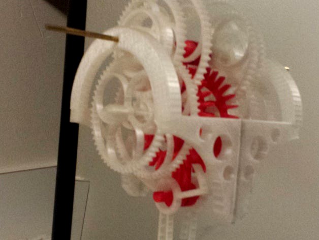
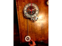
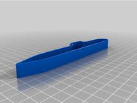
My second attempt at creating a simple, mechanical, weight-driven clock with the fewest parts. It uses 4mm brass shafts, a 1# drive weight, and currently, two ballpoint pens as the winding weight. The pendulum is a 1/4" aluminum tube, and I mounted it to a mirror. It works, but it needs improvement.
Specifically:
hands
a ratcheting winding system
a crutch system so that the pendulum does not have to swing as much
a clock face
a neater way to attach the weights
The gear train and escapement are pretty universal so that it may be rearranged (see the not overly accurate previous version in red). This also allows all parts to function with minimal post-print finishing.
Note: Gear tooth size and shaft holes are all very slightly offset inward to compensate for my printer's tendency to over-extrude.
UPDATE: As requested, I posted the additional parts needed to make the red (column) version of the clock (minus the holders for the quarters at the ends of the seesaw pendulum which I cannot find). To make this version, you'll need anything without "v2" in the file name plus wheel4v2. Even so, the pendulum needs to be adjusted to keep accurate time.
UPDATE 2: Added renders of the different gear configurations.
UPDATE 3:
Assembly instructions:
-Ensure gear teeth are free of artifacts and that all will rotate easily on their shafts.
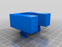
-Glue ONE of the mount pieces to whatever you are using as a backing (in my case, the mirror).
-Slot 4mm shafts into their mounts (you'll have to figure out the length).
-Take about 2m of cord and wrap it around the drum on wheel 4 (it took me three wraps of the necklace cord I used to develop sufficient friction with the weights I used).
-Onto the shaft in the shorter mount (the one connected to the pendulum pivot) slide the escape wheel, minute wheel (3), and hour wheel (5).
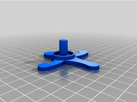
-On the taller mount slot the 60 tooth gear (2) and the wheel with the drum (4).
-With painstakingly minuscule adjustments, slide the unglued mount around until you find the sweet spot where the gears mesh with the least resistance.
-Glue the free mount in place on the backing once you are satisfied or out of patience.
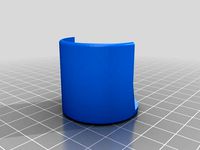
-Slide the arch-shaped frame piece on to the shaft with wheels two and four and glue the other frame pieces to the arch and the backing material using a similar process as described in the preceding two steps.
-Attach a pendulum to the anchor (using a simple pendulum close to 1m in length will yield the required two second period. Keep it light weight regardless and be prepared to spend time adjusting it)
-Tie the drive weight on the left side and the winding weight on the right side.
-Mount it to the wall
-Watch it tick
-Design and print some hands and otherwise modify it to your heart's content.
FYSA:
-However you mount the clock to the wall, ensure the pendulum is balanced so that the anchor achieves the same amount of lock in each direction.
-Since the main shaft is cantilevered, ensure the mount is robust enough to prevent it from getting pushed sideways from sustained torque from the weight. PLA to mirror is not robust enough without the right glue.
-This was a very early escapement design, so unless the pendulum swings sufficiently, it behaves more like a recoil escapement than a Graham escapement. I might improve it eventually.
UPDATE 4:
I added a new escape wheel and anchor that should be more efficient as mentioned in the previous update. They are untested as I do not currently have printer access, but they worked well in a computer simulation.
Also user Zarlor made these excellent assembly animations for both configurations which are probably easier to follow than my posted instructions.http://gph.is/2alyFDRhttp://gph.is/2aYdpDL
UPDATE 4.1 I re-uploaded the new anchor with slightly trimmed pallets and slightly less drop. This should prevent you from have to trim them by hand or sand down the back side of the escape teeth. Again, this is an untested modification.
UPDATE 5: I added a two piece mount and frame. Using these parts should eliminate all of the tedious wiggling and adjusting as described above during assembly. The caveat is that your printer must be very accurate (unlike my old printer on which I first printed this design) to ensure the gears mesh properly. Also, the frame will resist the flexural stress from the clock weight with the part's z-axis which is the weakest dimension. Be careful of adding too much weight (especially if you use a pulley).
Specifically:
hands
a ratcheting winding system
a crutch system so that the pendulum does not have to swing as much
a clock face
a neater way to attach the weights
The gear train and escapement are pretty universal so that it may be rearranged (see the not overly accurate previous version in red). This also allows all parts to function with minimal post-print finishing.
Note: Gear tooth size and shaft holes are all very slightly offset inward to compensate for my printer's tendency to over-extrude.
UPDATE: As requested, I posted the additional parts needed to make the red (column) version of the clock (minus the holders for the quarters at the ends of the seesaw pendulum which I cannot find). To make this version, you'll need anything without "v2" in the file name plus wheel4v2. Even so, the pendulum needs to be adjusted to keep accurate time.
UPDATE 2: Added renders of the different gear configurations.
UPDATE 3:
Assembly instructions:
-Ensure gear teeth are free of artifacts and that all will rotate easily on their shafts.
-Glue ONE of the mount pieces to whatever you are using as a backing (in my case, the mirror).
-Slot 4mm shafts into their mounts (you'll have to figure out the length).
-Take about 2m of cord and wrap it around the drum on wheel 4 (it took me three wraps of the necklace cord I used to develop sufficient friction with the weights I used).
-Onto the shaft in the shorter mount (the one connected to the pendulum pivot) slide the escape wheel, minute wheel (3), and hour wheel (5).
-On the taller mount slot the 60 tooth gear (2) and the wheel with the drum (4).
-With painstakingly minuscule adjustments, slide the unglued mount around until you find the sweet spot where the gears mesh with the least resistance.
-Glue the free mount in place on the backing once you are satisfied or out of patience.
-Slide the arch-shaped frame piece on to the shaft with wheels two and four and glue the other frame pieces to the arch and the backing material using a similar process as described in the preceding two steps.
-Attach a pendulum to the anchor (using a simple pendulum close to 1m in length will yield the required two second period. Keep it light weight regardless and be prepared to spend time adjusting it)
-Tie the drive weight on the left side and the winding weight on the right side.
-Mount it to the wall
-Watch it tick
-Design and print some hands and otherwise modify it to your heart's content.
FYSA:
-However you mount the clock to the wall, ensure the pendulum is balanced so that the anchor achieves the same amount of lock in each direction.
-Since the main shaft is cantilevered, ensure the mount is robust enough to prevent it from getting pushed sideways from sustained torque from the weight. PLA to mirror is not robust enough without the right glue.
-This was a very early escapement design, so unless the pendulum swings sufficiently, it behaves more like a recoil escapement than a Graham escapement. I might improve it eventually.
UPDATE 4:
I added a new escape wheel and anchor that should be more efficient as mentioned in the previous update. They are untested as I do not currently have printer access, but they worked well in a computer simulation.
Also user Zarlor made these excellent assembly animations for both configurations which are probably easier to follow than my posted instructions.http://gph.is/2alyFDRhttp://gph.is/2aYdpDL
UPDATE 4.1 I re-uploaded the new anchor with slightly trimmed pallets and slightly less drop. This should prevent you from have to trim them by hand or sand down the back side of the escape teeth. Again, this is an untested modification.
UPDATE 5: I added a two piece mount and frame. Using these parts should eliminate all of the tedious wiggling and adjusting as described above during assembly. The caveat is that your printer must be very accurate (unlike my old printer on which I first printed this design) to ensure the gears mesh properly. Also, the frame will resist the flexural stress from the clock weight with the part's z-axis which is the weakest dimension. Be careful of adding too much weight (especially if you use a pulley).
Similar models
thingiverse
free

Pendulum Wall Clock Final v2 by lustertone
... smoothly. i also added a tiny bit more to the hour/minute/seconds gear shafts so they would not have much friction between them.
thingiverse
free

Test Jig #2 - Clock Script by syvwlch
...escapement with increased drop, i.e. smaller impulse faces. the intent is to remove the need to shave the teeth before it works.)
3dwarehouse
free
DIY #15 - Wooden Pendulum Clock (v2.6)
...ck. version 2.6 is updated from versions 2.4 and 2.5 to show the escapement anchor and timing wheel in their correct orientation.
thingiverse
free

Pendulum Clock by j0z
...he pieces, especially the bearings- i used hot glue and it works fine.
hope you guys enjoy, remember to like and post your make!
thingiverse
free
Pendulum by aviyahalom
...ng gears but the were too rigid and prevented the mechanism from turning.
you can view a video here: https://youtu.be/tlrrfoftqls
thingiverse
free

Bullzeye Clock Remix by Legedus83
...les for small screws to connect each other from the back frame. the hex insert part never really fit into it's hole properly.
thingiverse
free

Wind car shaft support mod by Perry_S
... i had trouble with the unsupported shafts so i designed this snap in piece to support the shafts and ensuring correct gear mesh.
thingiverse
free

Weight for swinging pendulum by bre
...hole in this for m5 threaded rod. you can use this for your clock as a pendulum weight. fill with pennies and adjust as you like.
grabcad
free

Wooden Clock
.../8’’ / 3.175mm endmill.
- custom escapement with adjustable pallets.
to do:
- pendulum weight
- escapement weight
- clock hands
thingiverse
free
Pendulum Wall Clock Test v1 by lustertone
...ess by switching filaments at specific print levels.
i am currently rechecking everything to ensure that all parts are optimized.
A26
3d_export
$29

Kitchen A26 3D Model
...kitchen a26 3d model
3dexport
kitchen
kitchen a26 3d model ivaylo 43637 3dexport
turbosquid
$19

Booth Exhibition Stand a26
...bition stand for download as 3ds, max, obj, fbx, dwg, and upk on turbosquid: 3d models for games, architecture, videos. (1421093)
3dfindit
free

A26
...a26
3dfind.it
catalog: abb low voltage & systems
thingiverse
free

SAAB A26 Blekinge-class Submarine cookie cutter by Mulle_Meck
...submarine cookie cutter by mulle_meck
thingiverse
saab a26 blekinge-class submarine cookie cutter. scale it for different sizes.
thingiverse
free
SAAB A26 Blekinge-class Submarine cookie cutter by Mulle_Meck
...submarine cookie cutter by mulle_meck
thingiverse
saab a26 blekinge-class submarine cookie cutter. scale it for different sizes.
thingiverse
free
A26 Invader prop feathering switch guard by Fredco
...as a26 invader.
museum item located wings museum, balcombe, west sussex.
designed from original douglas drawing by aaron simmons.
thingiverse
free

A26 Yoke cap and centre cap by Fredco
...a26 yoke cap and centre cap by fredco
thingiverse
items designed for an aircraft at the wings museum - west sussex.
thingiverse
free

Lust Sculpture by A26
...e. it's perfect for singles, people that object to valentine's day, people that object to superficial pop art, and more!
thingiverse
free

Wet Bar by A26
...int a scaled down "mini bar" based around a 12 x 12 mirror panel, a 9" task light, and airplane bottles as a gift.
thingiverse
free
New frameb for Flying Tourbillon Model 1.5 by A26 by joesephus
...0tring gear, halting the mechanism. to remedy this, i added a ring on the frameb to reduce the effect, which seemed to work fine.
Clock
3d_ocean
$4
Clock
...clock
3docean
clock hand kitchen clock time watch
a clock
archibase_planet
free

Clock
...clock
archibase planet
clock table clock alarm-clock
clock orange - 3d model (*.gsm+*.3ds) for interior 3d visualization.
archibase_planet
free

Clock
...clock
archibase planet
clock table clock alarm-clock
clock yellow - 3d model (*.gsm+*.3ds) for interior 3d visualization.
archibase_planet
free
Clock
...clock
archibase planet
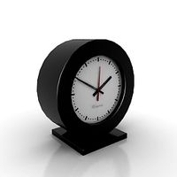
clock alarm-clock
clock n100707 - 3d model for interior 3d visualization.
archibase_planet
free
Clock
...clock
archibase planet
clock table clock
clock - 3d model (*.gsm+*.3ds) for interior 3d visualization.
archibase_planet
free
Clock
...clock
archibase planet
clock striking clock
clock - 3d model (*.gsm+*.3ds) for interior 3d visualization.
archibase_planet
free
Clock
...clock
archibase planet
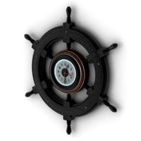
clock wall clock
clock 1 - 3d model (*.gsm+*.3ds) for interior 3d visualization.
archibase_planet
free
Clock
...clock
archibase planet
clock wall clock
clock 2 - 3d model (*.gsm+*.3ds) for interior 3d visualization.
archibase_planet
free

Clock
...clock
archibase planet
clock wall clock
clock 3 - 3d model (*.gsm+*.3ds) for interior 3d visualization.
archibase_planet
free
Clock
...clock
archibase planet
alarm clock alarm-clock
clock - 3d model (*.gsm+*.3ds) for interior 3d visualization.