Thingiverse

Chip-E Universal Expansion Kit by cordovalabs
by Thingiverse
Last crawled date: 3 years ago
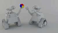
The Chip-E Universal Expansion Kit (Chip-E UEK) is a set of replacement parts for the RobotGeek 'Chip-E' - Open Source Arduino 3D Printed Robot. The Chip-E UEK (Chip-E Universal Expansion Kit) was designed for the Chip-E Remix Chanage.
The Chip-E UEK was designed to add Makerbeam aluminum extrusions to the outside corners of the body. These 100mm Makerbeam extrusions replaces all the standoffs that were used to hold the body of the Chip-E together (the Arduino standoffs are still needed). The Chip-E UEK's Makerbeam extrusions offer convenient hard points mounts for other external mods and/or add-ons. Additionally, the operator now has the ability to get to any part within the Chip-E UEK by only removing 4 M3 bolts.
Design Project: N/A
====================================================================
Printed Parts needed:
1x Head_MB_Mod
1x Top_MB_Mod
1x Midsection_MB_Mod
1x Base_MB_Mod
1x Shoe_Left from https://www.thingiverse.com/thing:1795648
1x Shoe_Right from https://www.thingiverse.com/thing:1795648
1x Foot_Left from https://www.thingiverse.com/thing:1795648
1x Foot_Right from https://www.thingiverse.com/thing:1795648
====================================================================
Hardware Needed:
Part that are listed in the original Chip-E's Part List or The Chip-E Kit
Up to 15x M3 nuts with Up to 15x M3 6mm Square Head Bolts or Up to 15x M3 nuts with Up to 15x M3 6mm Wing Type Head Bolts
8x M3 Screws (I used M3x16 but use a minimum of a M3x12)
4x Makerbeam Extruded Aluminium Beams 100mm
====================================================================
Info on Building:
See the Build instructions for Chip-E Universal Expansion Kit REV 0.pdf for Build instructions.
====================================================================
Info on the Design:
Up until the weekend of July 8th and 9th, I was not planning on entering the Chip-E Remix Chanage. But after seeing Flying Chip-E and the very cool The Zip-E Chip-E, I thought to myself, "These technical designs would be a lot easier if the Chip-E had the flexibility that some of my Sci Oly designs do".
As such I set myself the goal of making a Chip-E that had at least one aluminum extrusion built in. It turned out that having 4 would give me even more versatility in the Chip-E UEK.
I am a big fan of the use of aluminum extrusion in my designs. They offer an easy way of attaching something new to a design after the fact, and orders of magnitude easier than go through all the steps of remaking or remixing the original design files. After adding in the Makerbeam, I think the Chip-E has become more valuable to me as it could be a platform for future Science Olympiad or other Robotic competitions. I can now tack on tools, and end-effectors to the Chip-E (UEK) as needed to meet rules, to complete tasks, or just for the fun or it.
On a side note, I left the slope on the head of the Chip-E UEK in the hopes that the robot would retain some of its character that the original Chip-E had. However, I have yet to decide if it is worth keeping or not. I may in the future Remix my Remix to remove the slope and give it a block head.
Below are the "Should Include" for the Chip-E Remix Challenge:
Explaining your changes:
As noted above, I have added Makerbeam Aluminum extrusions to the corners of the Chip-E. This offers three advantages over the original design:
The user can access any level of the body by removing a maximum of 4 M3 screws.
Creates hard point mounts for future mods and/or add-ons
Removes and replaces the standoffs that where used to hold the body of the CHip-E together.
I hope that the Chip-E UEK means people that are not comfortable with or don't have the ability to work on other peoples CAD files can create mods for the platform.
How you remixed:
After importing and converting the *.step files that Robotgeeks included with the original Chip-E uploaded into something Fusion 360 can use, I started by figuring out how much space I could take away from the inside and still have the Chip-E be big enough for its hardware. It turned out I needed to leave as much space as I could so I did not interfere with the power plug, LCD, or battery.
As such, it was a lot easier to redesign the original body parts to hold about 1/2 of the Makerbeam and then extent the body left and right to make the Makerbeam flush with the edges of the body.
I then added the blocky corners to the head and base to allow for them to be attached to the Makerbeam with M3 screwes. Due to the limited hardware I had on hand, I designed the through hole corners to be compatible with the M3 x 16 screws I had on hand. This required me to thicken the Top (plate) to fill in the gap left by a missing 3 mm in the overall height of the Chip-E. I added walls to the bottom part of the Top Plate to allow for the Arduino standoffs to still function as designed.
Finally I added way to may holes into the midsection to allow for the midsection to be attached to the Makerbeam. This is not me just punching holes for the fun of it, I was trying to give the user of this design the flexibility to use any bolt pattern they want.
Any new skills you have given to Chip-E:
I gave Chip-E the ability to be expandable and modifiable without the person doing the changes having to completely redesign the body of the Clip-E.
Document the changes:
Noted Above
Similar models
thingiverse
free

project voron-01 sffpc case by NiceDepth
...pped, no modification is necessary.
print was done using pla+ on a flsun qq-s (upgraded fan duct and replaced stock timing belts)
thingiverse
free

Split LED holder for Ultimaker 2 Aluminum Extrusion 3D printer by dintid
... the corners that flushes the m5 and m3 hexagon socket head screws. you can find it here: http://www.thingiverse.com/thing:988809
thingiverse
free

Chip-E Remix with Bluetooth Control by charlesford
...have a bin of servos and electronics, i suggest that you purchase the robotgeek kit, which has all of the things you'll need.
3dwarehouse
free

Makerbeam Self Locking Bolt
...g bolt
3dwarehouse
please note this bolt is not original makerbeam and i have not tested it. #bolt #locking #m3 #makerbeam #self
thingiverse
free

Chip-e Minion by mauroalfieri
...ot.stl
n.1 minion_chip-e_body.stl
this are the original chip-e parts taht you have to print:
n.1 shoe_left.stl
n.1 shoe_right.stl
thingiverse
free

Bender Chip-e by daribes
... bracket
1 x geekduino
1 x robotgeek sensor shield
1 x battery
1 x robotgeek buzzer
1 x 2-line lcd
1 x ir receiver
1 x ir gamepad
thingiverse
free

The Meme Machine- Chip-E by GhostSkullStudios
...duino
1 x robotgeek sensor shield
1 x battery
1 x robotgeek buzzer
1 x 2-line lcd
1 x ir receiver
1 x ir gamepad
then you are set
thingiverse
free

Upper and Side brace for HyperCube (2020 extrusion) by saschai
...d a side bracket.
this bracket is decorative, for a large load is not intended ..
maybe someone needs it. i did not do this brace
thingiverse
free

MakerBeam 10x10 CornerCube by SP_Engineering
...your makerbeams with printed corners!
i am using stainless steel countersunk bolts with flat head for assemble (din7991 m3 x 6).
thingiverse
free

Chip-E - RobotGeek Biped by robotgeek
...de=embed" width="640" height="800" allowfullscreen="allowfullscreen" frameborder="0"
Cordovalabs
thingiverse
free

Wing Rib (2015 Science Olympiad) by cordovalabs
...is a simple wing rib for the 2014 science olympiad event, wright stuff.
the length of the rib is 66 mm and it is 1.5 mm thick.
thingiverse
free

CD/DVD Lightweigh Wheel Hub by cordovalabs
... was designed, to spec, for the hobbs high school science olympiad team. it was used as part of the second place gravity vehicle.
thingiverse
free

Gravity Vehicle (Science Olympiad 2013) by cordovalabs
...es, with very little modification.
note: this design has never been tested in competition and has no guarantee of performance.
thingiverse
free

Egg Block (2015 Science Olympiad) by cordovalabs
...attach it is glue.
note: at time of upload, the design has not been tested in competition and has no guarantee of performance.
thingiverse
free

Makerfire 4WD Replacement Motor Tabs by cordovalabs
...en tested on my letsrobot.tv robot for the past 5 months and have been holding up better then the one that came with the chassis.
thingiverse
free

War Hawk - Scrambler (2015 Science Olympiad) by cordovalabs
... using this design.
note: at time of upload, the design has not been tested in competition and has no guarantee of performance.
thingiverse
free

RoadRunner - Electrical Vehicle (2016 Science Olympiad) by cordovalabs
...re using this design.
note: at time of upload, the design has not been tested in competition and has no guarantee of performance.
thingiverse
free

Speed Bird - Scrambler (2015 Science Olympiad) by cordovalabs
... using this design.
note: at time of upload, the design has not been tested in competition and has no guarantee of performance.
thingiverse
free

Line Locator's Holsters by cordovalabs
...ng these holsters. these are made available as-is and i take no responsibility if you injure yourself while using these holsters.
thingiverse
free

Launcher Backpack - Scrambler (2015 Science Olympiad) by cordovalabs
...e old longer version.
note: at time of upload, the design has not been tested in competition and has no guarantee of performance.
Expansion
turbosquid
$42

Expansion tank
...d model expansion tank for download as 3ds, max, obj, and fbx on turbosquid: 3d models for games, architecture, videos. (1207393)
3d_export
$50

Expansion Joint 3D Model
...expansion joint 3d model
3dexport
expansion joint 3d model stargazer 4537 3dexport
turbosquid
$25
Titanic Expansion Joint
... available on turbo squid, the world's leading provider of digital 3d models for visualization, films, television, and games.
3d_export
$5
thermostatic expansion valve
...thermostatic expansion valve
3dexport
3d model stl of fusion 360.
3d_ocean
$15
Dungeon Tileset01 Expansion 1
...m/dungeon-tileset01-base/4625640 including stairs, tiles to make large rooms and a new texture that works with the tiles in th...
turbosquid
$20

Cartoon Corgi Banana Costume Expansion Pack
...artoon corgi banana costume expansion pack for download as ma on turbosquid: 3d models for games, architecture, videos. (1445388)
3ddd
$1

Hichory chair Ingold Oval Expansion
...kitchen-furniture/1911-collection/i510089-ingold-oval-expansion-top-mahogany-and-185-11-ingold-3-leg-pedestal-base.aspx
turbosquid
$299
Sci-Fi Dark Space Game Kit plus Expansion Pack
... available on turbo squid, the world's leading provider of digital 3d models for visualization, films, television, and games.
3d_export
$5
Swedish wall
...swedish wall 3dexport swedish wall, expansion wall bars, stairs for children, horizontal bar for...
3d_export
$10

External HDD 3D Model
...hard disk drive external seagate usb storage hdd portable expansion data mobile external hdd 3d model nkfrds 47740...
Chip
archibase_planet
free

Chips
...chips
archibase planet
chips potato chips crisps
chips - 3d model (*.gsm+*.3ds) for interior 3d visualization.
archibase_planet
free

Chips
...chibase planet
chips potato chips fast food food snack food
chips n180614 - 3d model (*.gsm+*.3ds) for interior 3d visualization.
archibase_planet
free

Chips
...archibase planet
chips crisps potato chips food fast food
chips 2 n180614 - 3d model (*.gsm+*.3ds) for interior 3d visualization.
3d_ocean
$5

Poker Chips
...poker chips
3docean
casino casino chips chips gambling poker poker chips roulette roulette chips
just poker chips set)
turbosquid
$15

chip
...ip
turbosquid
royalty free 3d model chip for download as c4d on turbosquid: 3d models for games, architecture, videos. (1492139)
3d_export
$5

chip
...chip
3dexport
сhip on the ground
turbosquid
$3

Chip
...
royalty free 3d model chip for download as max, fbx, and obj on turbosquid: 3d models for games, architecture, videos. (1604627)
turbosquid
$15

chips
... available on turbo squid, the world's leading provider of digital 3d models for visualization, films, television, and games.
turbosquid
$1

chip
... available on turbo squid, the world's leading provider of digital 3d models for visualization, films, television, and games.
archive3d
free

Chips 3D Model
...chive3d
chips potato chips crisps
chips - 3d model (*.gsm+*.3ds) for interior 3d visualization.
Kit
turbosquid
$3

Bathroom Kit Baño kit
... available on turbo squid, the world's leading provider of digital 3d models for visualization, films, television, and games.
turbosquid
$19

Kit
... available on turbo squid, the world's leading provider of digital 3d models for visualization, films, television, and games.
3d_export
$20
Drift Kit
...drift kit
3dexport
turbosquid
$40

BitCoin Kit
...urbosquid
royalty free 3d model bitcoin kit for download as on turbosquid: 3d models for games, architecture, videos. (1519068)
turbosquid
$9
Industrial kit
...osquid
royalty free 3d model industrial kit for download as on turbosquid: 3d models for games, architecture, videos. (1144117)
turbosquid
$6

Kit Vases
...
turbosquid
royalty free 3d model kit vases for download as on turbosquid: 3d models for games, architecture, videos. (1285114)
turbosquid
free
Survival Kit
...rbosquid
royalty free 3d model survival kit for download as on turbosquid: 3d models for games, architecture, videos. (1637721)
turbosquid
$50
Ninja Kit
...rbosquid
royalty free 3d model ninja kit for download as fbx on turbosquid: 3d models for games, architecture, videos. (1672364)
turbosquid
$35
Brushes Kit
...osquid
royalty free 3d model brushes kit for download as max on turbosquid: 3d models for games, architecture, videos. (1216721)
turbosquid
$19
Medical kit
...osquid
royalty free 3d model medical kit for download as fbx on turbosquid: 3d models for games, architecture, videos. (1486089)
Universal
3d_export
$20
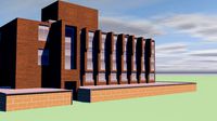
university
...university
3dexport
university model with textures.
3d_export
free

steven universe
...steven universe
3dexport
steven universe
3ddd
free

Quasar Universe
...quasar universe
3ddd
quasar
люстра quasar universe
turbosquid
$65
Universal
... available on turbo squid, the world's leading provider of digital 3d models for visualization, films, television, and games.
turbosquid
$65

University
... available on turbo squid, the world's leading provider of digital 3d models for visualization, films, television, and games.
turbosquid
$5

Universal
... available on turbo squid, the world's leading provider of digital 3d models for visualization, films, television, and games.
3d_export
$40
Graphics Universe Universe Flares 3D Model
...graphics universe universe flares 3d model
3dexport
textures
graphics universe universe flares 3d model crashangel 97554 3dexport
3d_export
$65

universe
...universe
3dexport
simple rendering of the scene file
3d_export
$65

university
...university
3dexport
simple rendering of the scene file
3ddd
$1
Gala Universal раковина
...universal раковина
3ddd
gala , universal
раковина
производитель gala
коллекция universal
E
3ddd
$1
WALL-E
...wall-e
3ddd
wall-e , робот
wall-e
3d_export
$100

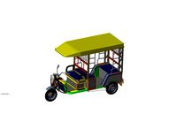
e-rickshaw
...e-rickshaw
3dexport
e-rickshaw- it have 3d model of passenger e-rickshaw
3d_ocean
$12
Wall E
...wall e
3docean
character robot wall e
its a 3d model of wall e….
turbosquid
$68
Model-E Droids 2-E Q-E Star Wars
... available on turbo squid, the world's leading provider of digital 3d models for visualization, films, television, and games.
cg_studio
$45
Model-E Droids 2-E Q-E Star Wars3d model
....3ds .c4d .obj .vue - model-e droids 2-e q-e star wars 3d model, royalty free license available, instant download after purchase.
3d_export
$100
e-rickshaw
...e-rickshaw
3dexport
e-rickshaw design for passenger it have all mechanical component
design_connected
$7

Cone E
...cone e
designconnected
bonaldo cone e computer generated 3d model. designed by pasini, ennio.
3ddd
$1

Wall-E NEW
...wall-e new
3ddd
wall-e , робот
wall-e
design_connected
$29

Extrasoft E
...extrasoft e
designconnected
living divani extrasoft e computer generated 3d model. designed by lissoni, piero.
3ddd
$1

E-Turn
... скамейка
современная скамейка фирмы kundalini.
модель e-turn.
дизайнер brodie neil.
размеры: h 42 cm l 185 cm w 54 cm