Thingiverse
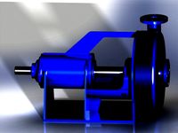
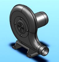
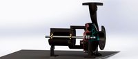
Centrifugal Pump by Ulf_vom_Mond
by Thingiverse
Last crawled date: 3 years, 4 months ago
Summary
Please read the description carefully. Not because it is relevant or helpful, but because i think its funny and interesting.
There already exist a lot of centrifugal pump designs on Thingiverse, so just go ahead and download this one: https://www.thingiverse.com/thing:4839
Still here? Ok, so i designed another one because the existing models didn't satisfy me. I also made another design myself previously, but i was still not happy.
The reason is that i dont know how all the pumps are designed.
Why do some pumps have straight blades, some two dimensional curved blades and some even three dimensional curved blades?
Why are some pumps thick and have a small diameter while others are thin with a large diameter?
Why do some pumps rotate forward and some backward? (Towards outer/inner edge of the blades)
How is the shape of the curved blades determined? Are they just drawn how they look good? How do i know the blades dont only look good for me, but for the water?
How much blades should the impeller have?
How i answered these questions can be found in How to design a centrifugal pump
The next thing bothering me was how to compare the different pump designs. Every design just named centrifugal pump (like mine) doesnt help much.
After some research i found two numbers to rate pumps:
The head they produce. Its just the height the pump can push water upwards.
The flowrate, thats the amount of water they can move per amount of time.
My experiments have established the following experience:
The first thing i found out is that the head of my pump is definitely larger than the border of my sink. The second thing i found out is that if i raised the end of the tube above 1.4 m above my pump, water still flows and shortly after that the cap comes off the pump case. On another attempt i got to 2 m head (which equals 0.2 bars of pressure) until the flow stopped without the pump breaking.
The flowrate wasn't as wet to measure and resulted in 7.5 litres per minute at a head of 0 m.
Another effect occured when operating the pump which may be taken into account: It was strong enough to drive my parents crazy. (Not yet, but it will when they wake up the next morning)
EDIT: yes it did!!!
Maybe the pump could be even better if it was tight. More about that in Print settings and Post-Printing.
The first piece of useful information: All tests were conducted with a little 12 V DC motor which consumes 0.6 W on idle.
Print Settings
Printer brand:
Creality
Printer:
CR-10
Rafts:
No
Supports:
Yes
Resolution:
0,2 mm
Infill:
15 %
Filament_brand:
Conrad Electronics
Filament_color:
black
Filament_material:
PLA
Notes:
Supports are only needed under the outlet of the case part. I think the material doesnt matter, just be careful about the water temperature. You may want to increase flow rate, shell line count and top/bottom layer count in order to make the pump more tight.
Post-Printing and Assembly
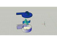
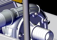
The pump case has a 6.7 mm hole at the bottom. Most little DC motors have a little edge which fits there perfectly. The impeller itself supports a 2 mm motor shaft, however, you have to file one side of the shaft flat to make it fit. It has to be filed until it measures 1.7 mm from the flat side to the opposing point of the round side. This is to ensure that the shaft isnt slipping in the impeller and it works pretty good. See this image for reference:
When your motor shaft fits, just put the parts together in the most obvious way. If you do something wrong there, i cant help you, too.
Then you should seal everything up water tight.
You can either do this the proper way and use silicone, which is made for this purpose and definitely water proof.
Or you can do it like me and use a hotglue. With a hotglue i dont mean a drop or a little or some hotglue, i mean something like a lot or much or a whole stick of hotglue. Your hotglue gun shouldnt make pfft it should make BLAAAAAARGHHHH while applying the glue. If you arent sure whether you used not enough or to less hotglue, you should add more.
These images tell you more about a hotglue:
(Yes, the tube adapter broke of in the second image. Be careful when removing the tube)
The tube adapters are designed for aquarium tubes with 12 mm inner diameter and 16 mm outer diameter. If the tubes dont fit, heat them up in a bowl of boiling water to make them soft and then push them over the adapters.
How to design a centrifugal pump
I used Fusion 360. You can access the design here: https://a360.co/3ixGKq7
About my used tolerances:
Everything that should fit tight together has a gap of 0.15 mm like the cap and the case.
The spinny thingy and the not so spinny thingy have a gap of radially 0.5 mm and axially 0.8 mm.
This part is really important to me as it was hard to find any solid information on the internet.
The things i found and used while designing are the following:
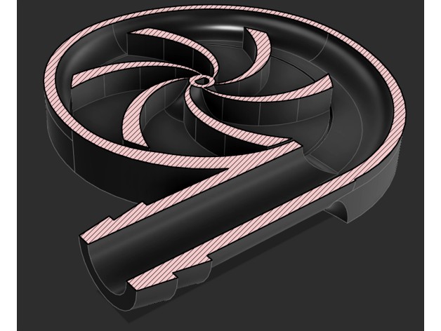
Centrifugal pump impeller vane profile
This article describes a conventional impeller blade design method in the Section 5.3 CONSTRUCTION OF VANE PROFILE. Thats the method i used and its called circular arc method.
A Review of Different Blade Design Methods for Radial Flow Centrifugal Pump
Here, further blade design methods are discussed which also may be helpful.
The Theory and Design of a Centrifugal Pump
Thats a bachelor thesis from 1911 which handles all the theory, but misses any practical advice on "how to do this" or "how to do that" but its quite interesting to read. Simply the fact that it was written on a typewriter made me curious.
Pump Handbook by Igor J. Karassik
This document probably contains every piece of information for every pump type on nearly 1800 pages (Why is this allowed to be called a handbook? I am happy that its digital because i could never even lift it). Its really interesting and has a lot of useful, detailed information. If you dont find your seeked knowledge there, it doesnt exist yet.
DESIGN AND ANALYSIS OF CENTRIFUGAL PUMP IMPELLER USING ANSYS FLUENT
Ajith MS made a good job simulating and comparing the different impeller blade design methods here. Its a nice addition if the 1800 pages werent enough for you.
Investigation of a centrifugal pump impeller vane profile using CFD
Another paper which researches the fluid dynamics of different impellers with simulation.
After reading a lot about pumps, this is how my sketch looks in Fusion 360:
I also included the impeller profile as a .svg and a .dxf file if you want to have a closer look.
Different pump sizes
If you need a different height, diameter, motor shaft, tube size or something else feel free to ask and i will upload your requested size. Thats not hard for me, so dont hesitate.
Please read the description carefully. Not because it is relevant or helpful, but because i think its funny and interesting.
There already exist a lot of centrifugal pump designs on Thingiverse, so just go ahead and download this one: https://www.thingiverse.com/thing:4839
Still here? Ok, so i designed another one because the existing models didn't satisfy me. I also made another design myself previously, but i was still not happy.
The reason is that i dont know how all the pumps are designed.
Why do some pumps have straight blades, some two dimensional curved blades and some even three dimensional curved blades?
Why are some pumps thick and have a small diameter while others are thin with a large diameter?
Why do some pumps rotate forward and some backward? (Towards outer/inner edge of the blades)
How is the shape of the curved blades determined? Are they just drawn how they look good? How do i know the blades dont only look good for me, but for the water?
How much blades should the impeller have?
How i answered these questions can be found in How to design a centrifugal pump
The next thing bothering me was how to compare the different pump designs. Every design just named centrifugal pump (like mine) doesnt help much.
After some research i found two numbers to rate pumps:
The head they produce. Its just the height the pump can push water upwards.
The flowrate, thats the amount of water they can move per amount of time.
My experiments have established the following experience:
The first thing i found out is that the head of my pump is definitely larger than the border of my sink. The second thing i found out is that if i raised the end of the tube above 1.4 m above my pump, water still flows and shortly after that the cap comes off the pump case. On another attempt i got to 2 m head (which equals 0.2 bars of pressure) until the flow stopped without the pump breaking.
The flowrate wasn't as wet to measure and resulted in 7.5 litres per minute at a head of 0 m.
Another effect occured when operating the pump which may be taken into account: It was strong enough to drive my parents crazy. (Not yet, but it will when they wake up the next morning)
EDIT: yes it did!!!
Maybe the pump could be even better if it was tight. More about that in Print settings and Post-Printing.
The first piece of useful information: All tests were conducted with a little 12 V DC motor which consumes 0.6 W on idle.
Print Settings
Printer brand:
Creality
Printer:
CR-10
Rafts:
No
Supports:
Yes
Resolution:
0,2 mm
Infill:
15 %
Filament_brand:
Conrad Electronics
Filament_color:
black
Filament_material:
PLA
Notes:
Supports are only needed under the outlet of the case part. I think the material doesnt matter, just be careful about the water temperature. You may want to increase flow rate, shell line count and top/bottom layer count in order to make the pump more tight.
Post-Printing and Assembly
The pump case has a 6.7 mm hole at the bottom. Most little DC motors have a little edge which fits there perfectly. The impeller itself supports a 2 mm motor shaft, however, you have to file one side of the shaft flat to make it fit. It has to be filed until it measures 1.7 mm from the flat side to the opposing point of the round side. This is to ensure that the shaft isnt slipping in the impeller and it works pretty good. See this image for reference:
When your motor shaft fits, just put the parts together in the most obvious way. If you do something wrong there, i cant help you, too.
Then you should seal everything up water tight.
You can either do this the proper way and use silicone, which is made for this purpose and definitely water proof.
Or you can do it like me and use a hotglue. With a hotglue i dont mean a drop or a little or some hotglue, i mean something like a lot or much or a whole stick of hotglue. Your hotglue gun shouldnt make pfft it should make BLAAAAAARGHHHH while applying the glue. If you arent sure whether you used not enough or to less hotglue, you should add more.
These images tell you more about a hotglue:
(Yes, the tube adapter broke of in the second image. Be careful when removing the tube)
The tube adapters are designed for aquarium tubes with 12 mm inner diameter and 16 mm outer diameter. If the tubes dont fit, heat them up in a bowl of boiling water to make them soft and then push them over the adapters.
How to design a centrifugal pump
I used Fusion 360. You can access the design here: https://a360.co/3ixGKq7
About my used tolerances:
Everything that should fit tight together has a gap of 0.15 mm like the cap and the case.
The spinny thingy and the not so spinny thingy have a gap of radially 0.5 mm and axially 0.8 mm.
This part is really important to me as it was hard to find any solid information on the internet.
The things i found and used while designing are the following:
Centrifugal pump impeller vane profile
This article describes a conventional impeller blade design method in the Section 5.3 CONSTRUCTION OF VANE PROFILE. Thats the method i used and its called circular arc method.
A Review of Different Blade Design Methods for Radial Flow Centrifugal Pump
Here, further blade design methods are discussed which also may be helpful.
The Theory and Design of a Centrifugal Pump
Thats a bachelor thesis from 1911 which handles all the theory, but misses any practical advice on "how to do this" or "how to do that" but its quite interesting to read. Simply the fact that it was written on a typewriter made me curious.
Pump Handbook by Igor J. Karassik
This document probably contains every piece of information for every pump type on nearly 1800 pages (Why is this allowed to be called a handbook? I am happy that its digital because i could never even lift it). Its really interesting and has a lot of useful, detailed information. If you dont find your seeked knowledge there, it doesnt exist yet.
DESIGN AND ANALYSIS OF CENTRIFUGAL PUMP IMPELLER USING ANSYS FLUENT
Ajith MS made a good job simulating and comparing the different impeller blade design methods here. Its a nice addition if the 1800 pages werent enough for you.
Investigation of a centrifugal pump impeller vane profile using CFD
Another paper which researches the fluid dynamics of different impellers with simulation.
After reading a lot about pumps, this is how my sketch looks in Fusion 360:
I also included the impeller profile as a .svg and a .dxf file if you want to have a closer look.
Different pump sizes
If you need a different height, diameter, motor shaft, tube size or something else feel free to ask and i will upload your requested size. Thats not hard for me, so dont hesitate.
Similar models
grabcad
free

Twist vane Impeller
...twist vane impeller
grabcad
impeller which is used in centrifugal pump
grabcad
free

centrifugal pump impeller and shaft
...centrifugal pump impeller and shaft
grabcad
a small practice mode of centrifugal pump impeller and its shaft
grabcad
free

Impeller Blades
...esigned using- catia v5 * work file uploaded in .catpart
surface modelling made in - solidworks 2018
material assigned- aluminium
grabcad
free

Enclosed Impeller
...the two shrouds. closed-impellers are installed on radial flow centrifugal pumps and can be either single inlet, or double inlet.
grabcad
free

Centrifugal Impeller
...centrifugal impeller
grabcad
a centrifugal compressor impeller
number of vanes: 8 blades and splitters
grabcad
free

Centrifugal impeller
...centrifugal impeller
grabcad
it is an impeller of centrifugal pump i have designed. it is just a model.
grabcad
free

Water Pump
...t, direct it into the impeller and then slow and control the fluid before discharge.
centrifugal pump specification: 125-100-250
grabcad
free

Reverse Vane Impeller
...the fluid being pumped by accelerating it from the center of the impeller to the outside of the impeller.
impeller overhung pump
grabcad
free

centrifugal pump
...tating impeller along its axis and is cast out by centrifugal force along its circumference through the impeller's vane tips.
thingiverse
free
Mini Impeller type Water pump by electricdiylab
...a mini 12v dc motor
i have also attached a cad drawing if you required to do some modification you can do.
www.electricdiylab.com
Ulf
3ddd
$1

mirror Epoca by Ulf Moritz
... ulf moritz
5 зеркал разных размеров с различными вариантами компоновки.
∅ 80 мм
∅ 120 мм
∅ 240 мм
∅ 400 мм
∅ 700 мм
3ddd
free

Обои Marburg ulf moritz pearl
...f moritz pearl
3ddd
marburg
обои marburg ulf moritz pearl арт
76822, вложены diffuse, reflect и
bump карты, разрешение 750*2500
3ddd
$1

Kahrs Ulf
...loads/images/7/7d/7d6/7d6fe34e6b7e0a4c3c9df721ce01bcd787b22a8b.jpg
отдельная благодарность kalando81 за модель кресла.
3ddd
$1

Обои
...кому-нибудь пригодится. ссылка на всю коллекцию: wall-covering.ru/germany/marburg/pearl/pearl.htm коллекция "pearl". "ulf moritz™". marburg wallcoverings (германия)...
unity_asset_store
$5

Viking Ulf
...ur workflow with the viking ulf asset from maksim bugrimov. find this & other humanoids options on the unity asset store.
3d_sky
free
mirror Epoca by Ulf Moritz
...y
mirror epoca ulf moritz
5 mirrors of different sizes with different layout options. ∅ ∅ 80 mm 120 mm 240 mm ∅ ∅ ∅ 400 mm 700 mm
3d_sky
free

Wallpaper Marburg ulf moritz pearl
...er marburg ulf moritz pearl
3dsky
wallpaper marburg ulf moritz pearl art 76822, nested, reflect and diffuse bump map, 750 * 2500
3dfindit
free

4047-L-ONFF-1-ULF-1.6GPF
...4047-l-onff-1-ulf-1.6gpf
3dfind.it
catalog: whitehall
3d_sky
$8

Kahrs Ulf
...e.ru/uploads/images/7/7d/7d6/7d6fe34e6b7e0a4c3c9df721ce01bcd787b22a8b.jpg special thanks kalando81 model for the chair.
thingiverse
free
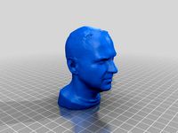
Cory Doctorow's decimated head for 3D printing - 16000 triangles by Ulf
...000 triangles by ulf
thingiverse
cory doctorow's 3d scanned head reduced to only 16,000 triangles with netfabb professional.
Vom
thingiverse
free

Meine Art vom Frosch by DirksBastelbude
...meine art vom frosch by dirksbastelbude
thingiverse
thingiverse
free

FIAT Luxus Wagon - vom munde abgespart by Syzguru11
...fiat luxus wagon - vom munde abgespart by syzguru11
thingiverse
fiat luxus wagon - vom munde abgespart
thingiverse
free

3D scan of Jüngling vom Magdalensberg by oliverlaric
...
3d scan of jüngling vom magdalensberg.
for more information visit http://threedscans.com/kunsthistorisches-museum-wien/jungling/
thingiverse
free

Halterung für Gummischutzbacken vom Proxxon Schraubstock by oobdoo
...roxxon schraubstock by oobdoo
thingiverse
ne kleine halterung wo ich die schutzbacken vom proxxon schraubstock aufbewahren kann.
thingiverse
free

FIAT Luxus Wagon mit schasdoernchen - vom munde abgespart by Syzguru11
...agon mit schasdoernchen - vom munde abgespart by syzguru11
thingiverse
fiat luxus wagon mit schasdoernchen - vom munde abgespart
thingiverse
free

FIAT Luxus Wagon vom munde abgespart / mother / phoenix by Syzguru11
... wagon vom munde abgespart / mother / phoenix by syzguru11
thingiverse
fiat luxus wagon vom munde abgespart / mother / phoenix
thingiverse
free

DJI Logo by Mike-vom-Mars
...corate your box, bag or controller. comes in two versions - solid and outlined.
use double sided tape, for example, to attach it.
thingiverse
free

Backen vom Greifer zum greifen von LED´s by JohnQgeL
...backen vom greifer zum greifen von led´s by johnqgel
thingiverse
for our project
thingiverse
free

Winged Heart Keychain by Mike-vom-Mars
... keychain
prints without supports, adding a brim may help for better heatbed adhesion since the parts are relatively small sized.
thingiverse
free

The Speedy Sperm by Mike-vom-Mars
...s with a black marker after printing. can be printed in various sizes.
no supports needed
no infill required, prints good without
Centrifugal
turbosquid
$209

Carpet centrifuge
...royalty free 3d model carpet centrifuge for download as sldas on turbosquid: 3d models for games, architecture, videos. (1445260)
turbosquid
$32

Centrifugal Pump
... free 3d model centrifugal pump for download as sldas and ige on turbosquid: 3d models for games, architecture, videos. (1643069)
3d_export
$12
Centrifugal Pump 3D Model
...centrifugal pump 3d model
3dexport
centrifugal pump
centrifugal pump 3d model fau 71172 3dexport
3d_export
$7
zy series centrifugal blower
...zy series centrifugal blower
3dexport
zy series centrifugal blower
3d_export
$20
Centrifugal pump 3D Model
... 3d model
3dexport
pump centrifugal turbomachinery turbo water machines industry
centrifugal pump 3d model qepasol 93421 3dexport
archive3d
free
Centrifuge 3D Model
...d
centrifuge spin dryer
dlc-213 n281107 - 3d model (*.gsm+*.3ds) for interior 3d visualization.
3d_export
$8
Centrifuge Laboratory 3D Model
...oratory centrifuge
centrifuge laboratory 3d model download .c4d .max .obj .fbx .ma .lwo .3ds .3dm .stl 3d1startup 105313 3dexport
3d_export
$7

centrifugal compressor
...ded, and also, step file and .stl files are also given so that anyone can operate this 3d model in any other designing softwares.
turbosquid
$120

Centrifugal Space Station
... available on turbo squid, the world's leading provider of digital 3d models for visualization, films, television, and games.
3d_export
$8

centrifugal fan 4-72-12 b4-72-12 no6 d c centrifugal fan
...centrifugal fan 4-72-12 b4-72-12 no6 d c centrifugal fan
3dexport
[centrifugal fan] 4-72-12, b4-72-12, no6 d, c centrifugal fan
Mond
3ddd
$1

Maisons du monde
... фоторамка , часы
декортивный набор maisons du monde
3ddd
free
Maisons Du Monde
... свеча , фоторамка , часы
maisons du monde
3ddd
$1

Maisons du monde PIRATE
...f surfer plaques. maisons du monde
-ковер manufacture rug. maisons du monde
-постельное белье maisons du monde
присутствует fbx
3ddd
$1

Maisons du Monde Velvet
...maisons du monde velvet
3ddd
maisons du monde
maisons du monde velvet child's armchair
polys: 41509
3ddd
$1

Maisons Du Monde
... свеча , тумба , часы
maisons du monde
3d_export
$5

maisons-du-monde-diamant
...maisons-du-monde-diamant
3dexport
maisons-du-monde-diamant
3ddd
$1

Maisons du monde ROBOT
...-постер ensemble de 2 toiles robot. maisons du monde
-подушки set of 4 robot child’s cushions. maisons du monde
присутствует fbx
3ddd
free

Maisons du monde CAMPUS
... monde
-постер andrews usa flag wall art. maisons du monde
-книги
-светофор
-карандаши
-рисунки
-меловая доска
присутствует fbx
3ddd
$1
Sideboard Archibald Maison Du Monde
...e
3ddd
сервант , maison du monde
сервант archibald от maison du monde
размеры 215х177х48
3d_export
$5
lampe photographe maisons du monde
...lampe photographe maisons du monde
3dexport
lampe photographe maisons du monde
Pump
3d_export
$5
pump
...pump
3dexport
pump
archibase_planet
free

Pump
...pump
archibase planet
petrol pump petrol station gas station
pump - 3d model (*.gsm+*.3ds) for interior 3d visualization.
3d_ocean
$8

Pumps
...ps
3docean
girls heels high kicks pumps shoes stilettos womens
womens high heels, pumps or stilettos. polygon model – no textures
3ddd
free
Pump
...ump
3ddd
pump , versus
производитель: versus
модель: pumphttp://www.versus.as/
turbosquid
$3
Pumps
...s
turbosquid
royalty free 3d model pumps for download as skp on turbosquid: 3d models for games, architecture, videos. (1275250)
3d_export
$5

pump
...pump
3dexport
turbosquid
$39
Realistic Water pump SYLLENT PUMP
...realistic water pump syllent pump for download as max and obj on turbosquid: 3d models for games, architecture, videos. (1312864)
turbosquid
$150

Pumpe
...yalty free 3d model pumpe for download as ige, blend, and stl on turbosquid: 3d models for games, architecture, videos. (1284318)
3d_export
$10
gear pump
...gear pump
3dexport
it is a gear pump in iges format
turbosquid
$19

Old Water Pumps Gas Pumps
...pumps gas pumps for download as 3ds, obj, fbx, blend, and dae on turbosquid: 3d models for games, architecture, videos. (1207997)