Thingiverse
Ceiling Projection Clock / Night light! by EDIV
by Thingiverse
Last crawled date: 3 years ago
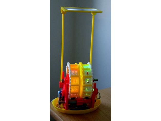
Ceiling Projection Clock / Night Light
The idea behind this was to create a nightlight/clock on the ceiling so that my children knew what time it was in the night – and stayed in bed!
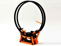
The idea is to shine an LED through a ‘cut-out’ of the time (hours and minutes) and focus this onto the ceiling to show the time. As the time changes the ‘cut-out’ is moved to show the new time.
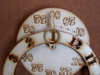
To do this I decided to have 2 wheels, one for hours and one for minutes. Each holds 12 ‘cut-outs’/stencils, one for each hour (1,2.. 11,12) and the other for each 5 minute interval (0,5…45,55). At night it is probably not necessary to know the time with better accuracy than 5 minutes. (For smaller children who can’t read numbers then these could be changed to suns, moons and other shapes!).
Since the resolution of a (my) 3D printer is not so great I decided to make the text approx. 1 cm high on a ¬20*20mm tile which could be slotted into each wheel.
To focus/image this onto a ceiling a lens is needed above the clock. The lens must be strong enough to form an image on the ceiling – initial tests with ‘cheap’ reading glasses showed that these were not strong enough. It should be noted that here there is a trade-off between strength of lens, magnification and LED brightness. If the focal length of the lens is short then it will need to be placed nearer to the clock – this in turn gives a larger magnification and means that LED may need to be brighter as the image is bigger, but also allows a smaller lens to be used as it is closer to the clock before the light has diverged so far. Conversely, a weaker lens would give a smaller image on the ceiling, it would need to be placed higher above the clock and would need to be bigger to capture the divergent rays. (If it is too weak then there will be no image – or at least it will be above the ceiling!)
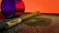
I then found some creditcard sized Fresnel lenses which were pretty good. They need to be placed ¬15 cm above the clock before the beam is too divergent and form a 10ish cm high image on the ceiling. They do however need a reasonably bright LED – I found a 1000mcd LED was easily visible at night and 10000mcd visible in the day!
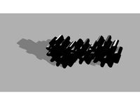
To drive the clock just one motor is used. A 28BYJ-48 stepper motor chosen as it is easily and cheaply available – the advantage of a stepper motor is that you know exactly how far it is going to rotate for a given number of steps. To keep the maths easy I decided to use a gear with 36 teeth for the large wheels. Since there 12 hours in the day and 12 five minute intervals in 1 hour then it must move 36/12 = 3 teeth at the time. The gear on the motor has 8 teeth, thus it must move 3/8s of a full turn for each 5 minutes. The gear box on my stepper motor had a gearing down of 1:64 – thus the number of steps could be calculated.
For the same reason the minute wheel has 3 teeth to drive the hour wheel forward by 1/12 of a revolution for each turn of the minute wheel.
To drive the stepper motor the small Arduino Nano (clone) was chosen which would fit inside the clock. The stepper motor comes with a driver board which can be directly connected to the Arduino.
Rather than use the stepper library, the motor can easily be tested/driven by sequentially pulsing the 4 pins high. I found that the minimum pulse duration of 2-3mS was needed for smooth movement – below this the motion was erratic.
To avoid potential damage to the Arduino/PC USB port you should disconnect any external power and the power connection between the Arduino and motor driver before (re)programming the device
Assembly
Once the parts are printed and cleaned up. Slot the hour and minute tiles into the Minute and Hour wheels. Make sure they are the correct way round or the projection may be inverted!, also on the minute wheel the ‘20’ tile should line up with the 3 teeth.
The Rings then fit over the tile pegs to hold the tiles in. It may be necessary to drill the holes in the ring and use glue to stop it falling off.
The Blinkers can also be fitted at this stage. These block stray light from the LEDs reaching the ceiling.
Extension wires should be soldered to the LEDs and the LEDs slotted in to the 2 LED holders.
The circuitry should follow the attached diagram.
The bolt holes may need to drilled out with a 6.5 mm drill.
Note the is also a small (4-5mm) spacer/washers between the 2 wheels
The motor gear should push tightly on the motor shaft.
The LED holders should be pushed in last as they block the wheels.
If the plates do not fit tightly then they can be glued.
The only other noteworthy thing is the yellow peg with a piece of grey filament sticking out in the photo. This pushes against the hour wheel to hold it in position and allow it to “click” from 1 hour to the next. If it is not fitted then the wheel can spin freely and show the wrong time. Another idea was to push the filament against the blinker to stop the wheel spinning, but this has not been tested.
Additional components
2x M6 90mm long bolts
Lens approx 15cm Focal length, wd 84 cm
Arduino Nano or similar
Super/Ultra bright LEDS (5mm, 1000-10000mcd)
Stepper motor 28BYJ-48
Mini 170 Tie Point Solderless Breadboard
5V PSU (I wouldn't recommend running it from a USB port)
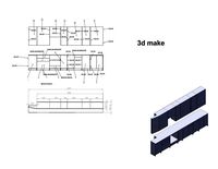
Alterations...
The Base can be extended upwards to hide the electronics/wires etc… Similarly a lid could be made - I intend to try it soon - now uploaded, although it is a bit bulky.
I found it is probably possible to remove the high lens holder by using stronger watchmakers magnifier -two will be needed (one for each wheel) and they can be placed much lower down. It may be necessary to change the LED angles so the 2 numbers do not overlap on the ceiling.
(The original idea was to have a projection clock onto the ceiling and a shadow clock point horizontally through the clock. The wheels were drawn up with hour numbers and minute indicators
)
Motor Info:-http://www.instructables.com/id/BYJ48-Stepper-Motor/https://arduino-info.wikispaces.com/SmallSteppershttps://grahamwideman.wikispaces.com/Motors-+28BYJ-48+Stepper+motor+notes
To create the gears I downloaded and used Gears 3D Print (https://gears-3d-printer.en.softonic.com/ ). This creates STL files of the gears which can then be scaled up/down/editted in a CAD program.
http://www.instructables.com/id/Make-an-accurate-Arduino-clock-using-only-one-wire/
The idea behind this was to create a nightlight/clock on the ceiling so that my children knew what time it was in the night – and stayed in bed!
The idea is to shine an LED through a ‘cut-out’ of the time (hours and minutes) and focus this onto the ceiling to show the time. As the time changes the ‘cut-out’ is moved to show the new time.
To do this I decided to have 2 wheels, one for hours and one for minutes. Each holds 12 ‘cut-outs’/stencils, one for each hour (1,2.. 11,12) and the other for each 5 minute interval (0,5…45,55). At night it is probably not necessary to know the time with better accuracy than 5 minutes. (For smaller children who can’t read numbers then these could be changed to suns, moons and other shapes!).
Since the resolution of a (my) 3D printer is not so great I decided to make the text approx. 1 cm high on a ¬20*20mm tile which could be slotted into each wheel.
To focus/image this onto a ceiling a lens is needed above the clock. The lens must be strong enough to form an image on the ceiling – initial tests with ‘cheap’ reading glasses showed that these were not strong enough. It should be noted that here there is a trade-off between strength of lens, magnification and LED brightness. If the focal length of the lens is short then it will need to be placed nearer to the clock – this in turn gives a larger magnification and means that LED may need to be brighter as the image is bigger, but also allows a smaller lens to be used as it is closer to the clock before the light has diverged so far. Conversely, a weaker lens would give a smaller image on the ceiling, it would need to be placed higher above the clock and would need to be bigger to capture the divergent rays. (If it is too weak then there will be no image – or at least it will be above the ceiling!)
I then found some creditcard sized Fresnel lenses which were pretty good. They need to be placed ¬15 cm above the clock before the beam is too divergent and form a 10ish cm high image on the ceiling. They do however need a reasonably bright LED – I found a 1000mcd LED was easily visible at night and 10000mcd visible in the day!
To drive the clock just one motor is used. A 28BYJ-48 stepper motor chosen as it is easily and cheaply available – the advantage of a stepper motor is that you know exactly how far it is going to rotate for a given number of steps. To keep the maths easy I decided to use a gear with 36 teeth for the large wheels. Since there 12 hours in the day and 12 five minute intervals in 1 hour then it must move 36/12 = 3 teeth at the time. The gear on the motor has 8 teeth, thus it must move 3/8s of a full turn for each 5 minutes. The gear box on my stepper motor had a gearing down of 1:64 – thus the number of steps could be calculated.
For the same reason the minute wheel has 3 teeth to drive the hour wheel forward by 1/12 of a revolution for each turn of the minute wheel.
To drive the stepper motor the small Arduino Nano (clone) was chosen which would fit inside the clock. The stepper motor comes with a driver board which can be directly connected to the Arduino.
Rather than use the stepper library, the motor can easily be tested/driven by sequentially pulsing the 4 pins high. I found that the minimum pulse duration of 2-3mS was needed for smooth movement – below this the motion was erratic.
To avoid potential damage to the Arduino/PC USB port you should disconnect any external power and the power connection between the Arduino and motor driver before (re)programming the device
Assembly
Once the parts are printed and cleaned up. Slot the hour and minute tiles into the Minute and Hour wheels. Make sure they are the correct way round or the projection may be inverted!, also on the minute wheel the ‘20’ tile should line up with the 3 teeth.
The Rings then fit over the tile pegs to hold the tiles in. It may be necessary to drill the holes in the ring and use glue to stop it falling off.
The Blinkers can also be fitted at this stage. These block stray light from the LEDs reaching the ceiling.
Extension wires should be soldered to the LEDs and the LEDs slotted in to the 2 LED holders.
The circuitry should follow the attached diagram.
The bolt holes may need to drilled out with a 6.5 mm drill.
Note the is also a small (4-5mm) spacer/washers between the 2 wheels
The motor gear should push tightly on the motor shaft.
The LED holders should be pushed in last as they block the wheels.
If the plates do not fit tightly then they can be glued.
The only other noteworthy thing is the yellow peg with a piece of grey filament sticking out in the photo. This pushes against the hour wheel to hold it in position and allow it to “click” from 1 hour to the next. If it is not fitted then the wheel can spin freely and show the wrong time. Another idea was to push the filament against the blinker to stop the wheel spinning, but this has not been tested.
Additional components
2x M6 90mm long bolts
Lens approx 15cm Focal length, wd 84 cm
Arduino Nano or similar
Super/Ultra bright LEDS (5mm, 1000-10000mcd)
Stepper motor 28BYJ-48
Mini 170 Tie Point Solderless Breadboard
5V PSU (I wouldn't recommend running it from a USB port)
Alterations...
The Base can be extended upwards to hide the electronics/wires etc… Similarly a lid could be made - I intend to try it soon - now uploaded, although it is a bit bulky.
I found it is probably possible to remove the high lens holder by using stronger watchmakers magnifier -two will be needed (one for each wheel) and they can be placed much lower down. It may be necessary to change the LED angles so the 2 numbers do not overlap on the ceiling.
(The original idea was to have a projection clock onto the ceiling and a shadow clock point horizontally through the clock. The wheels were drawn up with hour numbers and minute indicators
)
Motor Info:-http://www.instructables.com/id/BYJ48-Stepper-Motor/https://arduino-info.wikispaces.com/SmallSteppershttps://grahamwideman.wikispaces.com/Motors-+28BYJ-48+Stepper+motor+notes
To create the gears I downloaded and used Gears 3D Print (https://gears-3d-printer.en.softonic.com/ ). This creates STL files of the gears which can then be scaled up/down/editted in a CAD program.
http://www.instructables.com/id/Make-an-accurate-Arduino-clock-using-only-one-wire/
Similar models
thingiverse
free
28BYJ Stepper Motor Ready Gears Different Sizes by Bojar10
...y gears different sizes by bojar10
thingiverse
8 teeth gear
10 teeth gear
12 teeth gear
gears perfectly fits 28byj stepper motor
thingiverse
free

Geared Clock Remix by 3DMB
... .2 each to fit the gears loosely.
put the minute and hour gears on with them set at 12 o'clock position. (facing each other)
thingiverse
free
holo clock by ekaggrat
...and the hour wheel.
buy at:
https://www.tindie.com/products/ekaggrat/holo-clock-2/
https://www.youtube.com/watch?v=1etiefq4aqg
thingiverse
free

Second Arduino Clock
... and others.
included in the thing files is a text file with the code for the arduino.
look for: arduinocodesecondclockbutton.rtf
thingiverse
free

60flaps * 2drums split flap display clock by itoshin
...t2tuigjosqwhttp://www.instructables.com/id/byj48-stepper-motor/http://www.instructables.com/id/real-time-clock-using-ds3231-easy/
grabcad
free

Planetary Gear Clock
...o track the hours. the project runs off of a stepper motor and an arduino. the parts are made with a cnc router and a 3d printer.
thingiverse
free

Parametric OpenSCAD Clock Gear Train (Hours, Minutes & Seconds) by syvwlch
... speed and mesh.
the only thing i was not able to do is to make the code recursive, because openscad does not support that. booh!
grabcad
free

Stepper motor 28BYJ-48
...stepper motor 28byj-48
grabcad
tiny stepper motor (28byj-48) with gears
thingiverse
free
Gear Clock. New design style. Minute face is the whole cutout of hour wheel gear. Minute hand is traditional type for easier reading. Stencil cut. by TexasLaser
...te past current hour.
stencil cut hour numbers on the hour wheel.
the whole design is one page and can be cut from a 12x12 sheet.
thingiverse
free
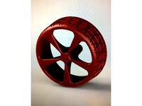
76mm -28BYJ-48 Stepper Motor Wheel by mr2quik
...per motor wheel by mr2quik
thingiverse
76mm x 32mm / 28byj-48 stepper motor wheel
attach to a 28byj-48 keyed stepper motor shaft
Ediv
thingiverse
free

Watering Can by EDIV
...verse
watering can.
watering can with playmobile sized handle.
can be printed without support - hence the strange handle shape!
thingiverse
free
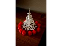
Mini Presents for Christmas Tree by EDIV
...itten on it - the kids choose a present and then had to hunt for the present with the given number on it - this was a great game!
thingiverse
free
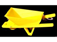
Toy wheelbarrow by EDIV
...ent. if scaling may be advisable to change hole size.
after quick sanding pieces snapped tightly together and no glue was needed.
thingiverse
free

Basic Crutch for Barbie by EDIV
...lide inside the cuff.
(123d file also includes original smaller crutch which may be suitable for smaller models/or thinner arms?)
thingiverse
free

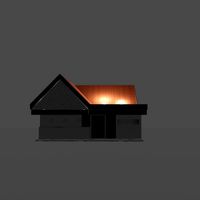
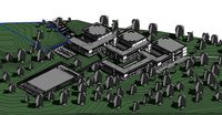
Lenzburg Castle by EDIV
... 123design and extruded up to give the buildings height (looking at aerial photos for comparison). finally the rooves were added.
thingiverse
free

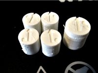
Toy bucket and drinking trough by EDIV
... to resolution of printer and had to printed on my basic printer in the "medium" and "high" quality settings.
thingiverse
free

Bike seatpost light leveller/wedge by EDIV
... a wedge would tend to do.
the size is made for a standard 27.2mm dia tube, simply scale on the printer for other seatpost sizes.
thingiverse
free

Magnet mount for bike speedo/odometer by EDIV
...magnet that came with the speedo.
some redrawing may be necessary if the magnet doesn't end up close enough to the switch...
thingiverse
free
Tyre dust cap to mark position on car of stored Summer / Winter tires by EDIV
...ould also make sure there are no loose pieces of filament that could fall in the tyre valve.
customise your own using the blank!!
thingiverse
free

LED Rail Lighting Kit! - Build your own under-shelf lighting, Christmas Tree, etc.. by EDIV
...mix)
rails can be steered using 45 and 90 degree bends.
rails can be attached/screwed to surfaces/under shelves using rod mounts.
Clock
3d_ocean
$4
Clock
...clock
3docean
clock hand kitchen clock time watch
a clock
archibase_planet
free

Clock
...clock
archibase planet
clock table clock alarm-clock
clock orange - 3d model (*.gsm+*.3ds) for interior 3d visualization.
archibase_planet
free

Clock
...clock
archibase planet
clock table clock alarm-clock
clock yellow - 3d model (*.gsm+*.3ds) for interior 3d visualization.
archibase_planet
free
Clock
...clock
archibase planet
clock alarm-clock
clock n100707 - 3d model for interior 3d visualization.
archibase_planet
free

Clock
...clock
archibase planet
clock table clock
clock - 3d model (*.gsm+*.3ds) for interior 3d visualization.
archibase_planet
free
Clock
...clock
archibase planet
clock striking clock
clock - 3d model (*.gsm+*.3ds) for interior 3d visualization.
archibase_planet
free
Clock
...clock
archibase planet
clock wall clock
clock 1 - 3d model (*.gsm+*.3ds) for interior 3d visualization.
archibase_planet
free
Clock
...clock
archibase planet
clock wall clock
clock 2 - 3d model (*.gsm+*.3ds) for interior 3d visualization.
archibase_planet
free

Clock
...clock
archibase planet
clock wall clock
clock 3 - 3d model (*.gsm+*.3ds) for interior 3d visualization.
archibase_planet
free
Clock
...clock
archibase planet
alarm clock alarm-clock
clock - 3d model (*.gsm+*.3ds) for interior 3d visualization.
Night
3ddd
$1
Кровать Night-Night Riva 1920
...кровать night-night riva 1920
3ddd
riva
http://www.riva1920.it/it/prodotti/letti/night-night-262/
3ddd
$1

Night Stand
... night stand , прикроватная тумба
classical night stand
3d_export
$5

Night castle
...night castle
3dexport
night castle
3d_export
$5

night table
...night table
3dexport
night table
3d_export
$5

dragon night
...dragon night
3dexport
dragon night 3d model
3d_export
$5
Night city
...night city
3dexport
night city with roads and houses
turbosquid
$21

Night
... available on turbo squid, the world's leading provider of digital 3d models for visualization, films, television, and games.
3d_export
$5

Foggy night
...foggy night
3dexport
move to a fabulous foggy night location.
3d_export
$5

King Of The Night
...king of the night
3dexport
king of the night. lord of the cold and the dead.
3ddd
$1
Night Stand
...night stand
3ddd
резьба , тумба
night stand for bedroom
Ceiling
3d_ocean
$5
ceiling lamp
...ceiling lamp
3docean
ceiling decoration lamp light
ceiling lamp
3ddd
$1
Ceil - Lamp
...ceil - lamp
3ddd
mouhamad asswad , ceil
ceil - lamp from i max render
3d_export
$269
ceiling lamp
...ceiling lamp
3dexport
ceiling lamp
3ddd
free
ceiling light
...ceiling light
3ddd
ceiling light
3d_export
$10
ceiling light
...ceiling light
3dexport
ceiling light branches
3ddd
$1
Ceiling Lamp
...ceiling lamp
3ddd
подвес
ceiling lamp
3d_ocean
$6
Ceiling fan
...ce blades ceiling ceiling fan cool cooling fan fixture
ceiling fan created in cinema4d. comes with various other formats as well.
turbosquid
$20
Plaster ceiling ornament, ceiling medallion
...iling ornament, ceiling medallion for download as max and obj on turbosquid: 3d models for games, architecture, videos. (1376554)
turbosquid
$17

Ceiling
... free 3d model ceiling for download as max, obj, fbx, and stl on turbosquid: 3d models for games, architecture, videos. (1367286)
3d_export
$5

ceiling fan
...ceiling fan
3dexport
a simple ceiling fan model.
Projection
3d_export
$7
project
...project
3dexport
project
3d_export
$20
Project
...project
3dexport
design_connected
$16

Project Chair
...project chair
designconnected
rex kralj project chair computer generated 3d model. designed by žitnik, marjan.
3ddd
$1
lectric Project
...настроены. сетка очень плотная.
доступно только для группы "profi"
про группу "profi" можно прочитать в чаво
3d_ocean
$19

Soon project
...kup. made in 3ds max 2013 1- 3dsmax with vray render included material and light 2- obj file 3- fbx file hope you like it plea...
turbosquid
$49
Joint | Project
...squid
royalty free 3d model joint | project for download as on turbosquid: 3d models for games, architecture, videos. (1297983)
turbosquid
$11
house project
...bosquid
royalty free 3d model house project for download as on turbosquid: 3d models for games, architecture, videos. (1672482)
turbosquid
$450
University project
...
royalty free 3d model university project for download as rvt on turbosquid: 3d models for games, architecture, videos. (1463354)
turbosquid
$30
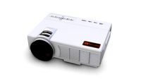
smart projecter
...lty free 3d model smart projecter for download as max and obj on turbosquid: 3d models for games, architecture, videos. (1236214)
3d_export
$5
project drawing
...project drawing
3dexport
project drawing and 3d model<br>format jpg sldprt dwg<br>by 3d make
Light
archibase_planet
free
Light
...light
archibase planet
lamp lighting light
light - s2 - 3d model for interior 3d visualization.
archibase_planet
free
Light
...light
archibase planet
light luminaire lighting
light l0465 - 3d model (*.gsm+*.3ds) for interior 3d visualization.
3d_export
$5
lighting
...lighting
3dexport
lighting
3d_export
$5

lighting
...lighting
3dexport
lighting in livingroom
turbosquid
$3
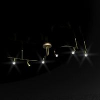
Lighting Tree with Lights
...d model lighting tree with lights for download as max and 3ds on turbosquid: 3d models for games, architecture, videos. (1585507)
archibase_planet
free
Light
...light
archibase planet
luster lighting solution
light - s - 3d model for interior 3d visualization.
archibase_planet
free
Light
...light
archibase planet
luster lamp lighting
light 1 - 3d model for interior 3d visualization.
archibase_planet
free
Lights
...lights
archibase planet
surgical lights surgical lamp
surgical lights (floor) - 3d model for interior 3d visualization.
archibase_planet
free
Light
...light
archibase planet
lighting luminaire candlelight
light l0463 - 3d model (*.gsm+*.3ds) for interior 3d visualization.
3d_export
$18
street light-lighting-light-xia bing
...
3dexport
street light-lighting-light-xia bing<br>max 2015 v-ray 3 max 2015<br>textures<br>all files in zip...