Thingiverse
Case for Papilio Duo FPGA and LCD Projects by elkayem
by Thingiverse
Last crawled date: 4 years, 7 months ago
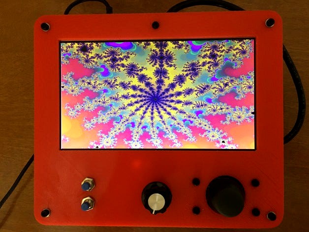
This is a simple case that will enclose the Papilio Duo FPGA board, 7" LCD screen, and analog joystick. I used it for a Mandelbrot fractal explorer project. I have made the SketchUp file available in case anyone wishes to tailor it for their own Papilio Duo project, e.g., a Papilio Arcade project, or even a project using another board such as a Raspberry Pi.
Here is a short YouTube video of my fractal project with this case. The text in the YouTube link contains more information about this FPGA project:https://youtu.be/OqxMnT_Ruuk
The code for this project can be found at: https://github.com/elkayem/Mandelbrot-Explorer
A few details on the hardware:
The mounting hole pattern is designed for the Papilio Duo, and mounts with M2 nylon bolts. It can be easily modified in SketchUp to mount a different board (e.g., other Papilio boards, Arduino, Raspberry Pi, Beaglebone, etc).
The LCD mount fits a 7" LCD screen with display driver board. The one I used can be found by searching "7 inch 1024*600 TFT LCD Display Driver Board HDMI VGA 2AV for Raspberry Pi" on eBay. I've included a picture of the one I used. The case design includes a mount for the display driver on the back of the LCD screen, using M2 nylon bolts.
A mount is included for a PS2 style analog joystick. There are a lot of joystick modules out there with slightly different hole patterns. I've included an image of the one I used, which is available from all the usual sources for a few dollars. Search for "joystick module arduino" and you should be able to find this one. Or modify the SketchUp for your own module. (Note: the Papilio Duo includes an AVR chip, programmable using the Arduino IDE. The analog joystick can be read by this AVR chip.)
My project required two buttons and rotary encoder, all of which required a 6mm diameter hole. Your own project may require something different. The hole placement and size can easily be modified in SketchUp.
The top and bottom of this case attach together using M3 standoffs. I used two 30mm male/female brass standoffs connected together. I intentionally did not raise the walls of the case all the way so I could easily access the electronics inside while the case is closed. Again, the walls can easily be raised in SketchUp if you desire a sealed case.
Hopefully someone finds this all useful. I admit it's a pretty specific application, but the design can be modified to suit your own project's needs.