Thingiverse

Can-Can-on by Schlauncha
by Thingiverse
Last crawled date: 3 years, 1 month ago
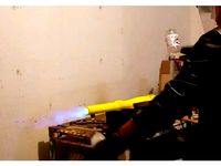
The .step and .iges files show all the plumbing fittings used, 10' long 3" diameter barrel surrounded by a 6" diameter pressure chamber 8' long, with a piston valve at the rear. 3D printed spacer keeps the 3" schedule 40 pvc barrel centered up in the 6" schedule 40 pvc pressure chamber. At the breech, a 1" pipe connects to a modified sprinkler valve, which dumps the air from behind the piston to suck it backward, allowing all air pressurized to 90psi in the chamber to now slam out through the barrel. A full pop can, placed in the sabot (printed with flexible TPU, like the valve) will be accelerated to roughly 500fps, with more muzzle energy than a 12ga shotgun. I am only posting this for information that is interesting, and I do not recommend anyone build this, because it will launch things farther than you can see, which could be dangerous if not used properly.
-- BUILD NOTES --
Fittings and materials needed:
All fittings should be Schedule 40 and/or list "PW", especially 6" fittings
10 feet of 3" schedule 40 pvc tube
10 feet of 6" schedule 40 pvc tube
Fittings in order of front to rear:
3" Tee (alter by adding hold through for muzzle brake, I used a lathe for this)
3" to 4" adapter bushing (alter by removing lip inside so 3" pipe slides through)
4" to 6" adapter bushing
6" pipe to 6" male thread adapter
6" female thread to 6" pipe adapter
8 feet cut from the 6" tube listed above for pressure chamber
6" schedule 40 pipe-to-pipe connector
6" to 4" bushing (alter to remove lip inside so 4" pipe slides through)
4" schedule 40 pipe-to-pipe connector
4" to (smaller) bushing
(smaller) to 1" NPT female thread bushing
1" NPT pipe 9" long extending to the rear from the last bushing
Going back to where we had 4" pipe now,
4" to 6" bushing (only glue to 4" pipe, and perhaps sand down outside slightly)
6" schedule 40 pipe-to-pipe connector (do not glue to bushing)
6" schedule 40 pipe approximately 6-8" long, so next fitting fits up flush as shown
6" pipe to 6" NPT female thread adapter
6" NPT threaded screw-in cap (alter with 1" clearance hole in center, add fittings for fill & trigger)
1" NPT threaded reducer tee (this goes onto the 1" pipe coming from the breech)
Reducer bushing going in reducer tee to get it down to 1/8 NPT female
1/8 NPT male 90 degree 1/4" air tube connection
The following gets mounted in the rear screw-in cap, using it as a solid wall and providing the air hose connection on the rear for filling:
1/4" air tube connection to 1/4 NPT female (may need a few pieces to adapt this)
1/4 NPT male air hose coupler fitting
Back to the tee, coming straight back in-line with the centerline:
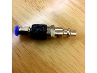
1" NPT sprinkler valve, modified to remove solenoid for faster direct triggering
1/8" NPT male 90 degree 1/4 air tube connection (threaded in where solenoid was)
Several feet of 1/4" air tube coming from the sprinkler valve's trigger back through cap
1/4" air tube to 1/4 NPT fitting
1/4 NPT tee
Pressure gauge off the side of the tee
1/4 NPT male-male short adapter
air blaster screwed on as the final piece, the trigger
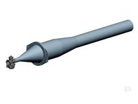
Prime and glue everything (except the threaded joints, and where the rear "can" slips over the sprinkler valve area) and make sure to use thread sealing tape on all threaded connections. The piston could be 3D printed as shown above, although currently I am just using a rubber cap for 4" tube glued over a 4" cap glued to a short piece of 4" tube, and then a 4" to 5" clay pipe rubber adapter that is flipped backwards so its larger diameter end (roughly 6" diameter outside - fitting the pressure chamber) is right around where the 4" tube cap is. The flat face of the 4" rubber cap is what seals against the end of the 3" barrel - I set the gap by putting a roll of duct tape in the breech, along with the piston, screwing the glued bushings into the front of the pressure chamber, and then taking the not-yet-glued 3" barrel and sliding it in until it hit, and gluing it there. After it cured, I unscrewed the barrel with its front bushings at the front 6" thread (the muzzle brake allows a smaller tube to pass through for leverage for unscrewing), and removed the roll of duct tape, leaving the piston with a few inches clearance to travel forward/backward between the breech and barrel. The inner end of the 3" barrel was carefully sanded very flat and perpendicular to the barrel's axis, so the valve would seal against it well. Procedure is to connect the air hose and allow it to pressurize to at least 20PSI (perhaps use a ball valve to control filling) so the piston seats to the barrel, and then load your projectile. If you load a projectile with zero pressure, the piston won't be up against the end of the barrel, and any wadding you have behind the projectile (I like using blocks of pillow foam) will expand out the back of the 3" barrel, preventing the piston from sealing against it. If the piston starts slightly pressurized so it's already sealed, then this isn't an issue. Once loaded and fully pressurized (I run 90PSI based on my air compressor's limitations) then when the air blaster is squeezed, the sprinkler valve's diaphragm now has low pressure behind it that you just vented, so the high pressure from inside can pop it open and flow out fast. This means that inside the breech, the pressure is holding the piston over the 3" barrel for starters, with 90PSI both ahead and behind the piston since it isn't a perfect seal, so it wants to stay forward as a cork in the only hole it sees low pressure, the 3" barrel. But when the sprinkler valve dumps out the air from behind the piston, now the piston has 6" diameter of low pressure behind it, 3" of low pressure ahead in the barrel, but the rest of the storage chamber is still pressurized to push back on the front of it, so it incredibly quickly will move to the rear, opening wide for all the chamber pressure to flow out the front.
Sorry for the rushed write-up, I just wanted to get a bunch of this info added to start with so it's at least listed.
Video of test firing (sorry for vertical video - I wasn't the one filming)https://youtu.be/_vxRjVACCRQ
Update 18MAY2017: added "rifler print" .stl files for tool that holds 6 pipe cutter replacement wheels (Plumb Works #694-3873) to pull through 3" schedule 40 PVC and cut rifling. Added "valve metric.stl" which is printed in flexible TPU and has tested successfully so far.
Update 30MAY2018: added parts for 4" barrel usage, such as concentrificator ring and sabots for baseballs and soda cans. Also added "Soda dart" which is a fin-stabilized projectile for holding a can of soda, where the fins spring inward as it is loaded into the 3" barrel, and they deploy by spring-action of the TPU material as it leaves the barrel. This is all a work in progress still, it seems we have problems with valve function now that we went to 4" barrel, but at least the 3" worked well. Another video if it wasn't already posted: https://youtu.be/-Bn7iZ-3Owk
-- BUILD NOTES --
Fittings and materials needed:
All fittings should be Schedule 40 and/or list "PW", especially 6" fittings
10 feet of 3" schedule 40 pvc tube
10 feet of 6" schedule 40 pvc tube
Fittings in order of front to rear:
3" Tee (alter by adding hold through for muzzle brake, I used a lathe for this)
3" to 4" adapter bushing (alter by removing lip inside so 3" pipe slides through)
4" to 6" adapter bushing
6" pipe to 6" male thread adapter
6" female thread to 6" pipe adapter
8 feet cut from the 6" tube listed above for pressure chamber
6" schedule 40 pipe-to-pipe connector
6" to 4" bushing (alter to remove lip inside so 4" pipe slides through)
4" schedule 40 pipe-to-pipe connector
4" to (smaller) bushing
(smaller) to 1" NPT female thread bushing
1" NPT pipe 9" long extending to the rear from the last bushing
Going back to where we had 4" pipe now,
4" to 6" bushing (only glue to 4" pipe, and perhaps sand down outside slightly)
6" schedule 40 pipe-to-pipe connector (do not glue to bushing)
6" schedule 40 pipe approximately 6-8" long, so next fitting fits up flush as shown
6" pipe to 6" NPT female thread adapter
6" NPT threaded screw-in cap (alter with 1" clearance hole in center, add fittings for fill & trigger)
1" NPT threaded reducer tee (this goes onto the 1" pipe coming from the breech)
Reducer bushing going in reducer tee to get it down to 1/8 NPT female
1/8 NPT male 90 degree 1/4" air tube connection
The following gets mounted in the rear screw-in cap, using it as a solid wall and providing the air hose connection on the rear for filling:
1/4" air tube connection to 1/4 NPT female (may need a few pieces to adapt this)
1/4 NPT male air hose coupler fitting
Back to the tee, coming straight back in-line with the centerline:
1" NPT sprinkler valve, modified to remove solenoid for faster direct triggering
1/8" NPT male 90 degree 1/4 air tube connection (threaded in where solenoid was)
Several feet of 1/4" air tube coming from the sprinkler valve's trigger back through cap
1/4" air tube to 1/4 NPT fitting
1/4 NPT tee
Pressure gauge off the side of the tee
1/4 NPT male-male short adapter
air blaster screwed on as the final piece, the trigger
Prime and glue everything (except the threaded joints, and where the rear "can" slips over the sprinkler valve area) and make sure to use thread sealing tape on all threaded connections. The piston could be 3D printed as shown above, although currently I am just using a rubber cap for 4" tube glued over a 4" cap glued to a short piece of 4" tube, and then a 4" to 5" clay pipe rubber adapter that is flipped backwards so its larger diameter end (roughly 6" diameter outside - fitting the pressure chamber) is right around where the 4" tube cap is. The flat face of the 4" rubber cap is what seals against the end of the 3" barrel - I set the gap by putting a roll of duct tape in the breech, along with the piston, screwing the glued bushings into the front of the pressure chamber, and then taking the not-yet-glued 3" barrel and sliding it in until it hit, and gluing it there. After it cured, I unscrewed the barrel with its front bushings at the front 6" thread (the muzzle brake allows a smaller tube to pass through for leverage for unscrewing), and removed the roll of duct tape, leaving the piston with a few inches clearance to travel forward/backward between the breech and barrel. The inner end of the 3" barrel was carefully sanded very flat and perpendicular to the barrel's axis, so the valve would seal against it well. Procedure is to connect the air hose and allow it to pressurize to at least 20PSI (perhaps use a ball valve to control filling) so the piston seats to the barrel, and then load your projectile. If you load a projectile with zero pressure, the piston won't be up against the end of the barrel, and any wadding you have behind the projectile (I like using blocks of pillow foam) will expand out the back of the 3" barrel, preventing the piston from sealing against it. If the piston starts slightly pressurized so it's already sealed, then this isn't an issue. Once loaded and fully pressurized (I run 90PSI based on my air compressor's limitations) then when the air blaster is squeezed, the sprinkler valve's diaphragm now has low pressure behind it that you just vented, so the high pressure from inside can pop it open and flow out fast. This means that inside the breech, the pressure is holding the piston over the 3" barrel for starters, with 90PSI both ahead and behind the piston since it isn't a perfect seal, so it wants to stay forward as a cork in the only hole it sees low pressure, the 3" barrel. But when the sprinkler valve dumps out the air from behind the piston, now the piston has 6" diameter of low pressure behind it, 3" of low pressure ahead in the barrel, but the rest of the storage chamber is still pressurized to push back on the front of it, so it incredibly quickly will move to the rear, opening wide for all the chamber pressure to flow out the front.
Sorry for the rushed write-up, I just wanted to get a bunch of this info added to start with so it's at least listed.
Video of test firing (sorry for vertical video - I wasn't the one filming)https://youtu.be/_vxRjVACCRQ
Update 18MAY2017: added "rifler print" .stl files for tool that holds 6 pipe cutter replacement wheels (Plumb Works #694-3873) to pull through 3" schedule 40 PVC and cut rifling. Added "valve metric.stl" which is printed in flexible TPU and has tested successfully so far.
Update 30MAY2018: added parts for 4" barrel usage, such as concentrificator ring and sabots for baseballs and soda cans. Also added "Soda dart" which is a fin-stabilized projectile for holding a can of soda, where the fins spring inward as it is loaded into the 3" barrel, and they deploy by spring-action of the TPU material as it leaves the barrel. This is all a work in progress still, it seems we have problems with valve function now that we went to 4" barrel, but at least the 3" worked well. Another video if it wasn't already posted: https://youtu.be/-Bn7iZ-3Owk
Similar models
grabcad
free

Pipe Clamp
...pipe clamp
grabcad
simple pipe clamp using pipe clamp ends and 3/4" schedule 40 pipe with npt threaded ends
grabcad
free

4" NPT PRESSURE VALVE
...4" npt pressure valve
grabcad
pressure valve with 4" npt thread
thingiverse
free
1/4" NPT to 4mm bowden adapter by chrismolloy
...t. it adapts a 1/4" npt fitting to a 4mm bowden style tube. threads are printed, so print with around 0.16mm layer height.
grabcad
free

Pipe Nipple, Configurable, 1/4" - 6", NPT
...t
currently schedule 80 pipe
adjust pipe i.d. to change pipe schedule if needed.
first upload so please leave feedback if needed.
thingiverse
free
RotoDamper 3 Adapter to 3/4" NPT threads by wbhinton
...ngiverse
35mm od bushing with 3/4" npt threads. created using https://www.thingiverse.com/thing:227192.
it fits perfect.
thingiverse
free

3/4" npt Tee by pfsternisha
...3/4" npt tee by pfsternisha
thingiverse
more pipe fittings.
grabcad
free

banjo fittings, nipples, hose barbs, ball valves, flanges, bushings, camlok, bulkhead fitting
..." close nipple
1" close nipple
bushing 2" npt x 1" npt
3" ansi flange, threaded
1" bulkhead fitting
grabcad
free

1/4" FNPT - 1/8" MNPT Pipe Fitting
...uot; female npt (national pipe thread) to 1/8" male npt (national pipe thread) brass pipe fitting reducer with 5/8" hex
grabcad
free

Finger Strainer P/N 05-17700
... is 16 mesh brass.
large finger strainer has a 3/8"-npt x 1/2"-m-npt brass bushing with a t304 stainless steel screen.
grabcad
free

Hydraulic Bushing #12 NPT x #4 NPT
...g used in hydraulic applications, note: #12 npt is equivalent to 3/4" pipe size & #4 npt is equivalent to 1/4" pipe
Schlauncha
thingiverse
free
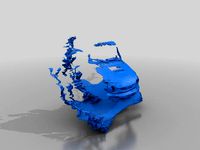
Sti Scans 1 by Schlauncha
...sti scans 1 by schlauncha
thingiverse
kinect v2 scans of suzuki x90 "sti"
thingiverse
free

Plug for Bigger Useless Box by Schlauncha
... i had to slightly trim the hole to get it to fit, but that was intentional because i wanted it to snap in tight and not rattle.
thingiverse
free

1/10 scale Coleman cooler by Schlauncha
...liner. adding airsoft bb's before gluing the lid on permanently gives a realistic sound of sloshing ice cubes / cans inside.
thingiverse
free
Pulsejet - 50lbs thrust by Schlauncha
...'t really recommend trying to 3d print this as it's not set up for it and doesn't have .stl's for each piece etc.
thingiverse
free
ShowYourNuts Fidget Spinner by Schlauncha
...on here with suitable center caps that could be used.
if you build one please be sure to share pictures of your results! thanks.
thingiverse
free
Zesty Nimble adaptor for CR-10 Plus with BL Touch & Tusk Cooling by Schlauncha
...in its retracted state
-designed to print without support when joint between two is to bed (.stl files not in proper orientation)
thingiverse
free
Zesty Nimble adapter for TrickLaser Rostock groove mount by Schlauncha
... in the prints). single biggest improvement in performance i've seen out of any of the upgrades i've done to my rostock.
thingiverse
free

Mad Max 6/71 Blower prop by Schlauncha
...upgrades.
the file blower.stp has been included for people to open the original solid model components and modify as they please.
thingiverse
free
PrintJet - the 3D printable pulsejet engine by Schlauncha
...otivates us to move forward with the bigger project (see my other design for a 50lb thrust version made from welded sheet metal).
Can
design_connected
$13

Can Can
...can can
designconnected
flos can can pendant lights computer generated 3d model. designed by marcel wanders.
3ddd
$1

Flos / Can Can
...
3ddd
can can , flos
подвесной светильник can can фабрики flos. дизайнер marcel wanders.
3d_ocean
$6
Cans
...cans
3docean
aluminium cans blender can cans food metal
set of cans (with label and without label). enjoy!
3ddd
$1

Flos Can Can
...для детской или гостиной.
основные технические характеристики:
высота (мм) 360 мм
диаметр (мм) 347 мм
категория ламп 150w e27
3ddd
$1

Can Can by Flos
...can can by flos
3ddd
flos
cancan byflos
3d_export
$5

Can
...can
3dexport
3d modeling of a beverage can. lies once in an obj. file and a stl. file.
3d_export
free
can
...can
3dexport
turbosquid
$15

Can
...can
turbosquid
royalty free 3d model can for download as max on turbosquid: 3d models for games, architecture, videos. (1260283)
turbosquid
$2

Can
...can
turbosquid
royalty free 3d model can for download as fbx on turbosquid: 3d models for games, architecture, videos. (1709812)
turbosquid
$44
Can
...osquid
royalty free 3d model can for download as c4d and obj on turbosquid: 3d models for games, architecture, videos. (1464835)