Thingiverse
Camera Slider / Dolly by Coder-Tronics
by Thingiverse
Last crawled date: 2 years, 12 months ago
Introduction
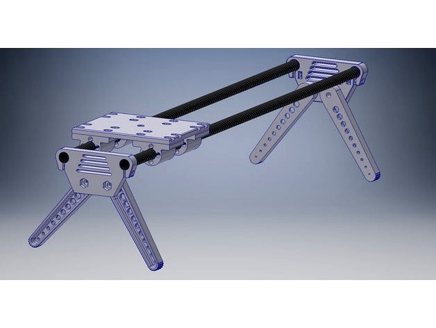
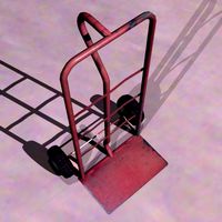
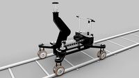
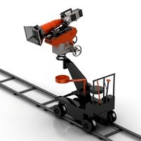
This is the first version of an almost fully 3D printed camera slider, using 10mm O/D carbon fibre rods and 4mm O/D PTFE solid rods as inserts for the bearings. I see this more as a proof of concept as my main aim is to make a small motorised version for time lapse photography, to be used with a GoPro primarily but also other small cameras and phones.
I wanted something light so it's good for hiking or travelling and this is also a way of testing the prototype bearings out.
There is a short video showing a basic assembly, as well as a quick video test and basic strength test.https://youtu.be/EmyTxzf4ODk
Printing
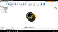
Everything is designed to be printed without support, you may have to flip/rotate some of the files to get them orientated (I sometimes accidentally use a different plane in Inventor).
I printed all of these at 0.2mm resolution with an infil of 30-40 percent. However, I would uses 50-60% for the end plates as the M3 bolts that lock the 10mm carbon fibre tubes, can split the layers if over tightened or if you have weak layer to layer adhesion. Turning the heat up to the upper end of your filaments temperature range can help with this.
I have also included .STP files as this might make it easier for anyone who wants to tweak the design.
Required Parts
Bearings
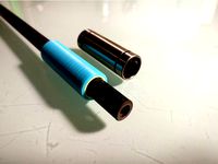
4mm PTFE rod - each bearing takes 4 x 30mm of rod, so 480mm in total. PTFE tube may well work here, but not tested as the rod was cheap from a UK supplier (far cheaper than Ebay or Aliexpress).
Carbon fibre Rods
2 x 10mm O/D x 500mm carbon fibre rods
End plates & Legs
4 x M5x20mm bolts (I used capped head here)
4 x M5 hex nuts
4 x M3x12mm or M3x16mm bolts (I used capped head here)
4 x M3 washers (these will help spread the load when securing the carbon fibre rods)
4 x M3 hex nuts
Fixing plate
16 x M3x12mm bolts (I used capped head here)
16 x M3 hex nuts
Assembly
This is pretty straightforward , there is a video showing the process for the main parts. The end plates can be mounted either way around.
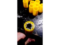
The bearing holes for the PTFE rod have a small coil rotation in them, to help grip the rod this does however make it a tight fit depending on which of the 4 bearing sizes you print. A little trial an error will be needed here as to which one is the best fit, my PTFE rod measured 4.5mm. I have made 4 sizes for the bearings and the first number represents the I/D of the bearing or O/D of the carbon fibre rod, the second dimension is the O/D of the PTFE rod.
Pending feedback I can add some larger sizes here, just drop me a comment and will try and upload in a few days.
Future Improvements
As mentioned there is a motorised version in the works, I will also try and reduce the number of bolts used for the top plate and may go to a 3 point version to also help with this.
Different types of legs are also an obvious improvement here, over the very basic ones currently available.
A quick release mechanism for the end plates and legs to allow quick assembly and disassembly.
This is the first version of an almost fully 3D printed camera slider, using 10mm O/D carbon fibre rods and 4mm O/D PTFE solid rods as inserts for the bearings. I see this more as a proof of concept as my main aim is to make a small motorised version for time lapse photography, to be used with a GoPro primarily but also other small cameras and phones.
I wanted something light so it's good for hiking or travelling and this is also a way of testing the prototype bearings out.
There is a short video showing a basic assembly, as well as a quick video test and basic strength test.https://youtu.be/EmyTxzf4ODk
Printing
Everything is designed to be printed without support, you may have to flip/rotate some of the files to get them orientated (I sometimes accidentally use a different plane in Inventor).
I printed all of these at 0.2mm resolution with an infil of 30-40 percent. However, I would uses 50-60% for the end plates as the M3 bolts that lock the 10mm carbon fibre tubes, can split the layers if over tightened or if you have weak layer to layer adhesion. Turning the heat up to the upper end of your filaments temperature range can help with this.
I have also included .STP files as this might make it easier for anyone who wants to tweak the design.
Required Parts
Bearings
4mm PTFE rod - each bearing takes 4 x 30mm of rod, so 480mm in total. PTFE tube may well work here, but not tested as the rod was cheap from a UK supplier (far cheaper than Ebay or Aliexpress).
Carbon fibre Rods
2 x 10mm O/D x 500mm carbon fibre rods
End plates & Legs
4 x M5x20mm bolts (I used capped head here)
4 x M5 hex nuts
4 x M3x12mm or M3x16mm bolts (I used capped head here)
4 x M3 washers (these will help spread the load when securing the carbon fibre rods)
4 x M3 hex nuts
Fixing plate
16 x M3x12mm bolts (I used capped head here)
16 x M3 hex nuts
Assembly
This is pretty straightforward , there is a video showing the process for the main parts. The end plates can be mounted either way around.
The bearing holes for the PTFE rod have a small coil rotation in them, to help grip the rod this does however make it a tight fit depending on which of the 4 bearing sizes you print. A little trial an error will be needed here as to which one is the best fit, my PTFE rod measured 4.5mm. I have made 4 sizes for the bearings and the first number represents the I/D of the bearing or O/D of the carbon fibre rod, the second dimension is the O/D of the PTFE rod.
Pending feedback I can add some larger sizes here, just drop me a comment and will try and upload in a few days.
Future Improvements
As mentioned there is a motorised version in the works, I will also try and reduce the number of bolts used for the top plate and may go to a 3 point version to also help with this.
Different types of legs are also an obvious improvement here, over the very basic ones currently available.
A quick release mechanism for the end plates and legs to allow quick assembly and disassembly.
Similar models
thingiverse
free
LM10UU PTFE lined bearing by Sylvainmartin
...g, 10mm pieces at each end of the bearing worked better then a full length 28mm ptfe piece. i got my 10mm ptfe tube from mcmaster
thingiverse
free

End Stop Holder for 10mm Rod by ChuckTheSquirrel
... holder for 10mm rod by chuckthesquirrel
thingiverse
end stop holder.
uses m3 x 20mm cap screws.
uses #4 x 1/2" wood screws
thingiverse
free

8mm Carbon Rod Right Angle Clamp by LLL003
...at 0.2mm layer with 30% fast hex infill in simplify 3d.
100% infill recommended if any appreciable twisting load will be applied.
thingiverse
free

Boeing 737 Rudder Pedals by usajet
...also will need 4mm to 6mm bolts and nuts etc. 4 608zz bearings.
7-29-2019 uploaded step file
i would love to see your builds!!:)
thingiverse
free
Igus 10mm Bushing Holder for LM8LUU by superjamie
...d or tube on the x axis, or just allows to not use a noisy metal linear bearing on a 10mm steel rod.
openscad source is included.
thingiverse
free
Prusa I3 10mm rods parts by villamany
... to use 3 o 4 bearings on the x carriage (two different .stl files)
sorry but my prusa i3 was sold and no pictures availables.
thingiverse
free

Monoprice select mini x-axis end cap with z-stabilizer bearing hole. by mfink70
... in the correct position. i'm not sure they will work with other mounts as i have only tested them with my side plate mounts.
grabcad
free

Air Engine
...ew
piston
cylinder
cap
back plate
connecting pipe (x 2)
two sided bolt
spring
round nut fastener
softwares used:
solidworks 2016
thingiverse
free

Hypercube Evolution X-Carriage for 10mm rods by trevor185
... fiber 10mm rods with ptfe bearings from mcmaster:https://www.mcmaster.com/#2685t13
my printer is assembled, but not running yet.
thingiverse
free

Cube Corners for 1m x 10mm rod by DJ2MN
...0mm rod by dj2mn
thingiverse
this is my customisation of platonic sold vertices for a 1m x 10mm carbon fibre rod cube structure.
Tronics
turbosquid
$26

Cartoon Tronic Bot
...toon tronic bot for download as 3ds, obj, fbx, blend, and dae on turbosquid: 3d models for games, architecture, videos. (1142974)
thingiverse
free

Solder Spool Holder X-Tronic 3020 by aegorsuch
...solder spool holder x-tronic 3020 by aegorsuch
thingiverse
lost the solder spool holder x-tronic 3020, reprinted here
thingiverse
free

Solder Spool Holder X-Tronic 3020 by aegorsuch
...solder spool holder x-tronic 3020 by aegorsuch
thingiverse
lost my solder spool holder for my x-tronic 3020, reprinted here
3dfindit
free

H-Tronic Universal Installations-Gehäuse, für Wandmontage oder Hutschiene TS 35
...h-tronic universal installations-gehäuse, für wandmontage oder hutschiene ts 35
3dfind.it
catalog: h-tronic
thingiverse
free

F-Tronic Fusebox Handle Clip by blackst225
....
the original clip from the oem part is required.
this is only the close mechanism that can break very easy
i hope this can help
3dbaza
$2

TRONIC A Chandelier (341712)
...496<br>xform: no<br>box trick: no<br>model parts: 13<br>render: v-ray<br>formats: 3ds max 2014, obj
thingiverse
free

Tao Tronics TT-AH002 Humidifier Chimney
...tao tronics tt-ah002 humidifier chimney
thingiverse
no supports
took about 30 min to print
3dbaza
$3

Anzazo TRONIC wall sconce (109114)
...lt;br>lighting area: 13 sqm<br>shade: ø 15 cm<br>dimensions: w 15 ø d 25 ø h 33-52 cm<br>wall mount: ø 15 cm
thingiverse
free

Gama Tronic King Kong New York LCD Game Battery Door / Cover by Neocrypton
... battery door / cover by neocrypton
thingiverse
a replacement batery cover for the lcd game from gama tronic, king kong new york
thingiverse
free

tao tronics uv flashlight 18650 adapter by remegade
...tronics uv flashlight 18650 adapter by remegade
thingiverse
flashlight took 3 aa so i made a 2 pc adapter to hold a single 18650
Coder
3d_export
$115

Magnitofon Sanyo 3D Model
...3dexport magnitofon sanyo electronic electric radio cassette record recorder coder sound audio mono stereo receiver player tape columns microphone...
3d_export
$30

High quality sound system 3D Model
...mic record condenser column team studios radio cassette recorder coder mono stereo columns analog low high poly 3d model...
thingiverse
free
Coder Dojo Medal
...coder dojo medal
thingiverse
a coder dojo inspired medal for coder dojo clubs!
thingiverse
free
Coder Dojo Pass
...coder dojo pass
thingiverse
a pass for coder dojo!
thingiverse
free

A by Rapid-Coder
...a by rapid-coder
thingiverse
thingiverse
free

QR Coder by JustinSDK
...e
ya! i have 1000 followers on thingiverse and the qr coder comes to celebrate with me. you may create your own qr coder, too :)
thingiverse
free

Dessert bowl for ninja coders by karthik9966
...dessert bowl for ninja coders by karthik9966
thingiverse
are you a ninja coder? no! not unless you eat from this!
thingiverse
free

Runout En-Coder Cube Back Remix by CrealityCheck
...e
this is remix of the case back for the runout en-coder-cube by rwmech. i added to tabs to be able to mount on my ender 5 pro.
thingiverse
free

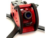
QAV CodeRed Micro Cam Mount And Optional Fin
...hingiverse
i didn't like the cam mount that they had for the codered frame so i made my own. it holds a 19mm size micro cam.
thingiverse
free
QAV CodeRed Camera Mount by Lumenier
... want to print the model yourself, you can get if from the link here:http://www.getfpv.com/lumenier-codered-tpu-camera-mount.html
Dolly
3ddd
$1
Baxter Dolly
...baxter dolly
3ddd
baxter
baxter dolly armchair
turbosquid
$35
Dolly
... available on turbo squid, the world's leading provider of digital 3d models for visualization, films, television, and games.
3ddd
$1

Baxter Dolly Sofa
...baxter dolly sofa
3ddd
baxter , dolly
baxter dolly sofa
3d_export
$7

dolly
...dolly
3dexport
zip and rar files attached below
3d_ocean
$25

Dolly
...e your own funny film with this funny rigged character . this character available on 3d max check this video : http://youtu.be...
3ddd
$1

Kartell Dolly chair
...kartell dolly chair
3ddd
kartell
цветные стулья dolly
turbosquid
$5

Baxter dolly
...squid
royalty free 3d model baxter dolly for download as max on turbosquid: 3d models for games, architecture, videos. (1363338)
3d_ocean
$15
Camera dolly
...vie news operator track tv video
high quality camera dolly with track. made in cinema 4d but has multiple other formats included.
turbosquid
$15
sofa Dolly
...ty free 3d model sofa dolly for download as max, obj, and fbx on turbosquid: 3d models for games, architecture, videos. (1462666)
turbosquid
$5

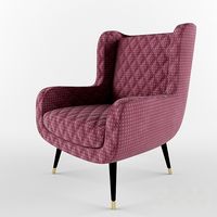
Armchair DOLLY
...ree 3d model armchair dolly for download as obj, c4d, and fbx on turbosquid: 3d models for games, architecture, videos. (1173489)
Slider
3d_export
$5
slider
...slider
3dexport
slider
3d_export
$5

Camera Slider
...camera slider
3dexport
camera slider toy
turbosquid
$10

SLIDER RAW
... available on turbo squid, the world's leading provider of digital 3d models for visualization, films, television, and games.
turbosquid
free

Slider V1
... available on turbo squid, the world's leading provider of digital 3d models for visualization, films, television, and games.
turbosquid
free

Vitrocsa3001-Slider-Fixed
... available on turbo squid, the world's leading provider of digital 3d models for visualization, films, television, and games.
3ddd
$1

ЭКМИ-МЕБЕЛЬ / Регина-slider
...er
3ddd
угловой , экми-мебель
диван "регина-slider". производитель экми-мебель
3d_ocean
$12
Bolt Cutter (Xpresso Slider Controlled)
...are to use slider controller. you can see how to use slider in preview video. render system and materials are ready. c4d and o...
3ddd
free

Шкатулка-держатель для фотографий Slider
...рмы umbra. вмещает три фотографии размером 8 х 8 см, 10 х 10 см и 10 х 15 см.http://www.umbra.com/usd/slider-photo-dis
3d_ocean
$9
Seats with Automatic Adding Slider (Xpresso)
... / images and read description carefully before you buy. thanks. you need cinema 4d software to use slider controller or just ...
turbosquid
$15

Computer Camera Slider, closes and opens camera view
...der, closes and opens camera view for download as skp and stl on turbosquid: 3d models for games, architecture, videos. (1331206)
Camera
archibase_planet
free
Camera
...base planet
camera surveillance camera video camera
camera surveillance n090211 - 3d model (*.3ds) for interior 3d visualization.
archibase_planet
free

Camera
...hibase planet
camera security camera video camera
camera security n210515 - 3d model (*.gsm+*.3ds) for exterior 3d visualization.
archibase_planet
free
Camera
...se planet
camera web camera webcam
camera butterfly usb pc camera n090713 - 3d model (*.gsm+*.3ds) for interior 3d visualization.
archibase_planet
free
Camera
...mera
archibase planet
surveillance camera video camera camcorder
camera n011211 - 3d model (*.3ds) for exterior 3d visualization.
archibase_planet
free
Camera
...camera
archibase planet
camera digital camera
camera canon digital n041211 - 3d model (*.3ds) for interior 3d visualization.
archibase_planet
free
Camera
...camera
archibase planet
camera film camera phototechnique
camera n100214 - 3d model (*.gsm+*.3ds) for interior 3d visualization.
archibase_planet
free
Camera
...amera
archibase planet
camera video camera camcorder
camera video n070315 - 3d model (*.gsm+*.3ds) for interior 3d visualization.
archibase_planet
free
Camera
...rchibase planet
camera video camera camcorder
camera studio n101213 - 3d model (*.gsm+*.3ds+*.max) for interior 3d visualization.
archibase_planet
free
Camera
...ibase planet
digital camera camera phototechnique
camera canon ixus 400 n310311 - 3d model (*.3ds) for interior 3d visualization.
archibase_planet
free
Camera
...ase planet
photocamera video camera camera
camera sony t300 black n291010 - 3d model (*.gsm+*.3ds) for interior 3d visualization.