Thingiverse
Camera Mount for OpenAstroTracker using Tripod Mount (SCAD) by qwertylkjhgfdsamnbvc
by Thingiverse
Last crawled date: 4 years ago
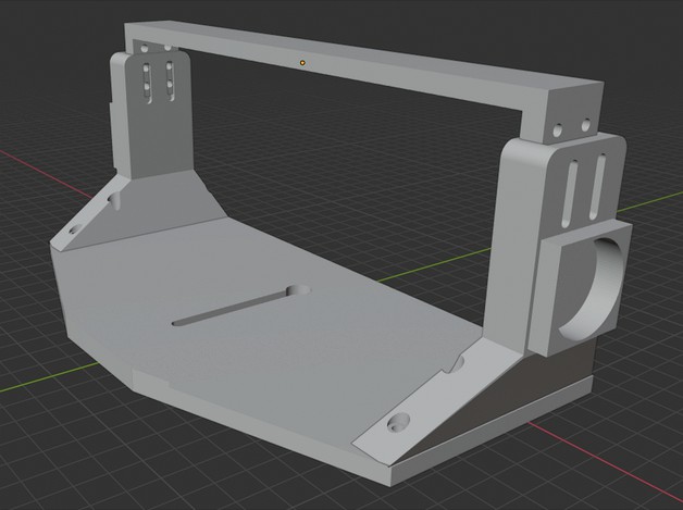
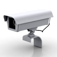
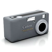
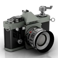
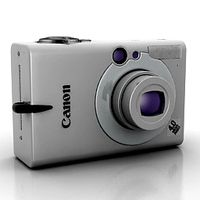
This is a SCAD version of the Canon 7D Camera mount for OpenAstroTracker by jeffcapeshop to the best of my abilities. Like the original design, this is mainly intended for individuals who have their center of gravity too close to the camera body to use the normal amount. Instead, it utilizes the tripod mount on the camera to interface with the OpenAstroTracker (https://www.thingiverse.com/thing:4167783)
This is my first time using SCAD so I commented as much as I could to reduce the confusion when reading the file. Like jeffcapeshop's version, this hasn't been tested as I am still in the process of making my own tracker. Additionally, most of the dimensions for this model were taken from jeffcapeshop Fusion 360 file. To compensate for this, there is a relatively easy was to customize most of the dimensions at the top of all of the files. Also, I would like to apologize for any bugs in the code as I suspect that there are many.
Additionally, I would like to make this one file rather than two. Since I am new to SCAD, I don't know of a way to do this. Any help would be appreciated! :)
HOW TO USE:
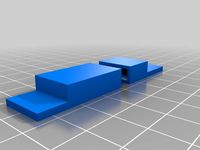
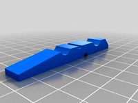
There are three SCAD files. One is for the base plate where the camera mounts, another other is for the side pieces where it attaches to the tracker and the last one is to generate the top support (This is optional).
Open a the SCAD file labeled SideMount.SCAD. You will see two sections for variables. One specific variable section to that file and a shared variable section.
Additionally, there is variable at the top called "Direction". Setting this to "1" or any other value will produce a Right or Left mounting bracket. Both left and right brackets are needed.
Change all the values that have the comment "//**CHANGE** SPECIFIC TO CAMERA". These are values specific to each camera and would have to be added. This should be done for both the specific and shared variable section in the SideMount.SCAD file.
After changing all the values that you want, copy the entire shared variable section from the file that you edited to the mountPlate.SCAD and support.SCAD (If you chose to use the top support) file overwriting the shared variable section there.
The top support is mainly for structural concerns to make the whole rig more stable. This may not be necessary as this hasn't been tested. Top support can be easily turned off or on.
There are additional parameters in the file:
Variables tagged: "//Shouldn't need to change" are regarding the actual dimensions of the part and only need to be changed if it doesn't fit or work. Please let me know if there are any adjustments so that I can upload new files.
Variables tagged: "//If u wanna change" are mainly personal preference and nothing major should happen if you change these values. These are mainly used to create a more customized fit.
There is also an option to use slots on the base plate. This would replace the mounting holes on the plate. This is done to add flexibility to move the mount forward or backward depending on the center of gravity. This can be toggled by setting the "UseSlots" variable to true or false.
Once again, this hasn't been tested to work. I will test and update as soon as I finish building my astrotracker (May take a while). :) Thank you to jeffcapeshop (u/catbo) and Fabian Uehleke (u/intercipere) for all of their hard work! If anyone has any improvements feel free to comment! I hope that this will become a viable alternative for individuals who have their center of mass too close to the camera body or just want one mount for multiple lenses.
Sorry for any formatting issues. Idk how to fix them or why they happened.
This is my first time using SCAD so I commented as much as I could to reduce the confusion when reading the file. Like jeffcapeshop's version, this hasn't been tested as I am still in the process of making my own tracker. Additionally, most of the dimensions for this model were taken from jeffcapeshop Fusion 360 file. To compensate for this, there is a relatively easy was to customize most of the dimensions at the top of all of the files. Also, I would like to apologize for any bugs in the code as I suspect that there are many.
Additionally, I would like to make this one file rather than two. Since I am new to SCAD, I don't know of a way to do this. Any help would be appreciated! :)
HOW TO USE:
There are three SCAD files. One is for the base plate where the camera mounts, another other is for the side pieces where it attaches to the tracker and the last one is to generate the top support (This is optional).
Open a the SCAD file labeled SideMount.SCAD. You will see two sections for variables. One specific variable section to that file and a shared variable section.
Additionally, there is variable at the top called "Direction". Setting this to "1" or any other value will produce a Right or Left mounting bracket. Both left and right brackets are needed.
Change all the values that have the comment "//**CHANGE** SPECIFIC TO CAMERA". These are values specific to each camera and would have to be added. This should be done for both the specific and shared variable section in the SideMount.SCAD file.
After changing all the values that you want, copy the entire shared variable section from the file that you edited to the mountPlate.SCAD and support.SCAD (If you chose to use the top support) file overwriting the shared variable section there.
The top support is mainly for structural concerns to make the whole rig more stable. This may not be necessary as this hasn't been tested. Top support can be easily turned off or on.
There are additional parameters in the file:
Variables tagged: "//Shouldn't need to change" are regarding the actual dimensions of the part and only need to be changed if it doesn't fit or work. Please let me know if there are any adjustments so that I can upload new files.
Variables tagged: "//If u wanna change" are mainly personal preference and nothing major should happen if you change these values. These are mainly used to create a more customized fit.
There is also an option to use slots on the base plate. This would replace the mounting holes on the plate. This is done to add flexibility to move the mount forward or backward depending on the center of gravity. This can be toggled by setting the "UseSlots" variable to true or false.
Once again, this hasn't been tested to work. I will test and update as soon as I finish building my astrotracker (May take a while). :) Thank you to jeffcapeshop (u/catbo) and Fabian Uehleke (u/intercipere) for all of their hard work! If anyone has any improvements feel free to comment! I hope that this will become a viable alternative for individuals who have their center of mass too close to the camera body or just want one mount for multiple lenses.
Sorry for any formatting issues. Idk how to fix them or why they happened.
Similar models
thingiverse
free

Nema17 Z-Axis & 120x120mm Heatbed-Mount for MicroCube by shinzo
...ezoid threaded rod with carry nut and an 120x120mm printbed. have a look at the other scad files for more customizable variables.
thingiverse
free

75mm/100mm Vesa monitor mount by rw86347
...r pla, with very thick walls. i am using a cr-10 to your bed may be smaller. this print should use approximately 240mm x 120mm.
thingiverse
free

customizable Bridge torture test with Height customisation by mer2329
...s as to how to remove the top circle from, the top. to do this you need to use open scad, as it uses comments, and not variables.
thingiverse
free

T Mount for 2" and 1.25" Eyepiece
... obviously. i am not responsible for any damage using this with your camera.
update: added the 1.25" (31.75mm) adapter also.
thingiverse
free

Remixed Camera Mounts for OpenAstroTracker by kevwill
... accept m3x30mm screws instead of the original m2x30mm screws.
i have included the updated stl files as well as the step files.
thingiverse
free

HoryzonHD V4 Camera - Tilt Mount by SiRkIt
...using any kind of 3d modeling or cad software. my 3d printer isn't all that dialed in. so any feed back would be appreciated.
thingiverse
free
Tslot power supply mount by PeterEllens
... i'm using the mount under my hypercube. ignore the long screws in the image...i just didn't have the short ones needed.
thingiverse
free

NEMA 17 1:48 hypocycloid test by PolyVinalDistillate
...nteresting test that proved it worked!
note - the linked-to scad file isn't exactly neat and tidy! sorry!! (still learning)
thingiverse
free
MPCNC tool mount nut trap by robbertkl
...kness) for my own reference. the nut traps were made to fit my m4 nyloc nuts. i glued them in.
also see the matching drill guide.
thingiverse
free

Round Lattice Box by MotivatedTea
...lattice box by motivatedtea thingiverse another simple box generator, similar to my previous one, but round. i designed this...
Openastrotracker
thingiverse
free

M14 Thumb Screw for OpenAstroTracker by Theworld
...rld
thingiverse
m14 thumbscrew with round end for the openastrotracker. 60 mm long although the useable length is a little less.
thingiverse
free

OpenAstroTracker UNO Case
...se: https://www.amazon.co.uk/dp/b0716jmhnj/
connectors need to be crimped. i used this one: https://banggood.app.link/3m8zmscbs4
thingiverse
free

OpenAstroGuider - Autoguiding add-on for the OpenAstroTracker
...and pull to focus for now.
as always, cad files are on github and the source code for the ascom driver is in the trackers github
thingiverse
free

OpenAstroTracker All in One E.Box by dotstars
...esigned for the uln32003. but with something craft, you can also install the other driver boards for tcm2209 and others. see pic.
thingiverse
free
Remixed Camera Mounts for OpenAstroTracker by kevwill
... accept m3x30mm screws instead of the original m2x30mm screws.
i have included the updated stl files as well as the step files.
thingiverse
free

OpenAstroTracker Part14 200x200 bed
...openastrotracker part14 200x200 bed
thingiverse
a shorter part 14 if you're printing on a 200x200 print bed.
thingiverse
free

Remix of OpenAstroGuider for OpenAstroTracker by kevwill
...al design, i found it difficult to accurately focus the guider. i remixed it to use threaded fittings for more precise focusing.
thingiverse
free

OpenAstroTracker sectioned splitring
...section. my split ring now has 4 overlap joints instead of the 2 in the original design and the strength integrity is maintained.
thingiverse
free

Scope mount guide for 46mm tube on openastrotracker by nsozar
...pe, outside diameter 46mm, with a zwo camera asi224mc
link guide scope: https://a.aliexpress.com/_mmpxhw1
print 2 os this support
thingiverse
free

OpenAstroTracker Bearing Shim by CHARL13
... lose. i created these shims to sit between the roller bearings and the roller mounts to keep the bearings in the correct place.
Scad
turbosquid
$81

Yellowstripe scad animated fish low poly toon
...h low poly toon 3d model for download as ma, ma, fbx, and obj on turbosquid: 3d models for games, architecture, videos. (1585532)
3dfindit
free
SCAD
...scad
3dfind.it
catalog: te connectivity
thingiverse
free
THING, SCAD by kaixie
...thing, scad by kaixie
thingiverse
thing, scad
thingiverse
free

questionMark-scad by thingiversedeveloper
...questionmark-scad by thingiversedeveloper
thingiverse
trying out the scad
thingiverse
free
Clothespin scad by carlesoriol
...clothespin scad by carlesoriol
thingiverse
clothespin scad. don't pring the spring!!
thingiverse
free
Mr. SCAD by plangdon
...mr. scad by plangdon
thingiverse
max's first cad design - mr. scad
thingiverse
free

bague scad by TristanJ
...bague scad by tristanj
thingiverse
...
thingiverse
free
coupling scad config by wanick
...coupling scad config by wanick
thingiverse
scad file config sizes
thingiverse
free

made in open scad by BasejCar
...made in open scad by basejcar
thingiverse
made in open scad. use geb.scad
thingiverse
free

Test scad ring by NathanMichaelMoore
...test scad ring by nathanmichaelmoore
thingiverse
test upload of my first scad thing
Tripod
archibase_planet
free
Tripod
...tripod
archibase planet
tripod staff state stand
tripod - 3d model for interior 3d visualization.
archibase_planet
free
Tripod
...tripod
archibase planet
camera tripod
cam tripod 2 - 3d model (*.gsm+*.3ds) for interior 3d visualization.
archibase_planet
free
Tripod
...tripod
archibase planet
tripod support stand holder
tripod n191213 - 3d model (*.gsm+*.3ds+*.max) for interior 3d visualization.
design_connected
$13
Tripod
...tripod
designconnected
erickson æsthetics tripod computer generated 3d model. designed by erickson, ben.
design_connected
$13

Tripod
...tripod
designconnected
david weeks studio tripod computer generated 3d model. designed by weeks, david.
3d_ocean
$4
Tripod
...tripod
3docean
3d models coffee table furnishings furniture tripod
3d models,furnishings,furniture
archibase_planet
free
Tripod
...tripod
archibase planet
tv camera equipment
cam tripod - 3d model (*.gsm+*.3ds) for interior 3d visualization.
turbosquid
$4
Tripod
...urbosquid
royalty free 3d model tripod for download as blend on turbosquid: 3d models for games, architecture, videos. (1580064)
turbosquid
$5

Tripod
...uid
royalty free 3d model tripod for download as c4d and fbx on turbosquid: 3d models for games, architecture, videos. (1593078)
turbosquid
$35

Tripod
... available on turbo squid, the world's leading provider of digital 3d models for visualization, films, television, and games.
Camera
archibase_planet
free
Camera
...base planet
camera surveillance camera video camera
camera surveillance n090211 - 3d model (*.3ds) for interior 3d visualization.
archibase_planet
free
Camera
...hibase planet
camera security camera video camera
camera security n210515 - 3d model (*.gsm+*.3ds) for exterior 3d visualization.
archibase_planet
free
Camera
...se planet
camera web camera webcam
camera butterfly usb pc camera n090713 - 3d model (*.gsm+*.3ds) for interior 3d visualization.
archibase_planet
free
Camera
...mera
archibase planet
surveillance camera video camera camcorder
camera n011211 - 3d model (*.3ds) for exterior 3d visualization.
archibase_planet
free
Camera
...camera
archibase planet
camera digital camera
camera canon digital n041211 - 3d model (*.3ds) for interior 3d visualization.
archibase_planet
free
Camera
...camera
archibase planet
camera film camera phototechnique
camera n100214 - 3d model (*.gsm+*.3ds) for interior 3d visualization.
archibase_planet
free
Camera
...amera
archibase planet
camera video camera camcorder
camera video n070315 - 3d model (*.gsm+*.3ds) for interior 3d visualization.
archibase_planet
free
Camera
...rchibase planet
camera video camera camcorder
camera studio n101213 - 3d model (*.gsm+*.3ds+*.max) for interior 3d visualization.
archibase_planet
free
Camera
...ibase planet
digital camera camera phototechnique
camera canon ixus 400 n310311 - 3d model (*.3ds) for interior 3d visualization.
archibase_planet
free
Camera
...ase planet
photocamera video camera camera
camera sony t300 black n291010 - 3d model (*.gsm+*.3ds) for interior 3d visualization.
Mount
3d_export
free

mounting bracket
...mounting plate is the portion of a hinge that attaches to the wood. mounting plates can be used indoors, cabinetry and furniture.
turbosquid
$2

MOUNTING
... available on turbo squid, the world's leading provider of digital 3d models for visualization, films, television, and games.
turbosquid
free

Mounts
... available on turbo squid, the world's leading provider of digital 3d models for visualization, films, television, and games.
turbosquid
free

Mount Fuji
...fuji
turbosquid
free 3d model mount fuji for download as obj on turbosquid: 3d models for games, architecture, videos. (1579977)
3d_export
$5

Headphone mount LR
...headphone mount lr
3dexport
headphone mount l+r
turbosquid
$39

Mount rainier
...quid
royalty free 3d model mount rainier for download as fbx on turbosquid: 3d models for games, architecture, videos. (1492586)
turbosquid
$5

pipe mounting
...quid
royalty free 3d model pipe mounting for download as obj on turbosquid: 3d models for games, architecture, videos. (1293744)
turbosquid
$3

Mounting Tires
...uid
royalty free 3d model mounting tires for download as fbx on turbosquid: 3d models for games, architecture, videos. (1708511)
3d_export
$5

Magnetic GoPro Mount
...pro mount
3dexport
cool magnetic mount for gopro. allows you to mount the camera on flat metal surfaces and get exclusive shots.
turbosquid
$5

Stone Mount
...ty free 3d model stone mount for download as ma, obj, and fbx on turbosquid: 3d models for games, architecture, videos. (1370306)
Using
3ddd
$1

US flag
...us flag
3ddd
флаг
us flag
3d_export
free

Among us
...among us
3dexport
among us red
3d_export
free

Among Us
...among us
3dexport
this 3d-model of a character from the game "among us". it can be used as a toy or decoration.
3d_export
$6

among us
...among us
3dexport
doll from among us in red
3d_export
$5

amoung us
...amoung us
3dexport
amoung us character. was created by cinema 4d 19
3d_export
$5
Humvee us
...humvee us
3dexport
humvee us 3d model good quality for animation
3d_export
$15

among us
...among us
3dexport
turbosmooth modifier can be used to increase mesh resolution if necessary
3d_export
$25

mailbox us
...mailbox us
3dexport
low poly model mailbox us. modeling in the blender, texturing in substance painter
design_connected
$13
Use Me
...use me
designconnected
sitland use me computer generated 3d model. designed by paolo scagnellato.
3d_export
$5

Among Us
...rt
the among us model comes in a variety of colors that can be customized by anyone, and even works with little in the animation