GrabCAD
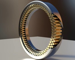
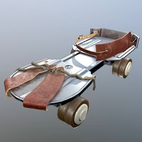
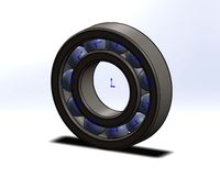
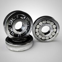
Cageless, Multilayered, Full Complement Radial Roller Bearing
by GrabCAD
Last crawled date: 1 year, 10 months ago
First of several different rolling element bearing concepts I came up with back in late 2013 - early 2014.
The principal innovative aspect of this bearing design is that even though the bearing is full complement, there is no sliding contact between consecutive rollers within the same row or layer of rolling elements.
Nor are the rollers inside the bearing being kept apart by a single, common cage which they would all rub against rather than each other.
This is due to the use of more than just one row of rolling elements. More specifically, 3 inter-meshed layers of rollers are used: an inner and outer layer and an intermediary, separating layer – which acts as a sort of load bearing rolling cage and keeps consecutive rolling elements in the other two layers from touching each other.
It is necessary to use an odd number of layers of rollers because if an even number of rows of rollers were used they would actually attempt to convey rotation from the bearing's inner race to its outer one (or the other way around), which would work against the purpose and role of the bearing of enabling easy, low friction (or other resistance) rotation of one shaft or other component in relation to another.
Using just two layers would mean that spinning the bearing would require and cause the rolling elements to actually travel in the opposite direction at a proportionally impractically high rate of speed.
Because of this the bearing has to have an odd number of layers of rollers. And using just one row of rolling elements would have been no different than regular bearings in ubiquitous use today, which exhibit sliding contact either between consecutive rolling elements or between these and a non-load bearing cage which keeps them separated.
The way the bearing is designed, the middle layer of rollers separates and prevents sliding contact between any two consecutive rollers in either the 1st and 3rd/last layer, acting as a sort of rolling cage analogous to the sliding cage in a regular roller bearing, which has just one row of rollers.
Conversely, consecutive rolling elements in the middle layer are themselves kept apart by rollers in the inner (1st) and outer (3rd) layers.
The purpose of the 'rolling cage' middle layer isn't just to keep consecutive rolling elements in the other two rows separate. It is also load bearing, as it conveys the load the bearing is supporting from its inner layer of rollers to its outer one.
Other envisaged and expected benefits of this bearing concept are that it should automatically and inherently accommodate rolling elements of slightly different radii occurring as a result of manufacturing tolerances, should inherently and implicitly balance load evenly across its rolling elements (despite possible unevenness in roller diameter as a result of manufacturing tolerances) and (I believe) it should also be self-centring.
I did attempt to submit the idea to various corporations which operate in the fields of mechanical engineering, machine, vehicle or device manufacturing or the manufacturing of components thereof.
I'm fairly sure I submitted detailed documentation outlining the concept to at least Bosch and the Schaeffler Group but the idea didn't seem to garner any attention or interest from any of the companies I tried conveying it to. The design has never been patented by myself and I was not demanding compensation in exchange for it, only asked to possibly be considered for hiring or reimbursed collaboration. Unfortunately, that did not come to pass.
Perhaps the design is fundamentally flawed or unavoidably impractical and therefore worthless and I just didn't realise this myself, not being trained or formally educated in mechanical engineering or any other field of engineering.
Similar models
grabcad
free

Cageless, Multilayered, Full Complement Radial Ball Bearing
...dn't realise this myself, not being trained or formally educated in mechanical engineering or any other field of engineering.
grabcad
free

Cageless, Multilayered, Full Complement Axial Tapered Roller Bearing
...cage which keeps them separated from each other but which they all slide or rub against, contributing to friction, heat and wear.
grabcad
free

Cageless, Multilayered, Full Complement Radial-Axial Tapered Roller Bearing - design 03
...complement radial-axial tapered roller bearing - design 03 grabcad similar to the 'cageless, multilayered, full complement axial roller bearing...
grabcad
free

Stacked Rolling Element Layered Radial-Axial Truncated Conical Roller Bearing
...complement tapered roller bearing, or between the rolling elements and their cage, in the case of a caged tapered roller bearing.
grabcad
free

Triple Rolling Element Layer Tapered Roller Axial Bearing.
...complement tapered roller bearing, or between the rolling elements and their cage, in the case of a caged tapered roller bearing.
grabcad
free

Rolling Cage Radial Bearing
...back burner until recently. this bearing design is mostly similar to regular, caged roller radial bearings currently in widespread...
grabcad
free

Cylindirical Roller Bearing
...ler bearings also have an inner ring that is separable from the outer ring, making it easier to install and maintain the bearing.
grabcad
free

Cylindirical Roller Bearing
...ler bearings also have an inner ring that is separable from the outer ring, making it easier to install and maintain the bearing.
grabcad
free

Ball Bearing
... cage.
a ball bearing is a type of rolling-element bearing that uses balls to maintain the separation between the bearing races.
grabcad
free

Roller Bearings
...bearings — also known as rolling-element bearings — are similar to ball bearings in that they are designed to...
Cageless
thingiverse
free
Mini-pump holder for cageless bottle mounts by NickSalter68
...two bottles, the spare mount can be used to carry a mini-pump (in this case a lezyne pocket drive). a bit niche but works for me!
thingiverse
free

Cageless Roller Bearing by tobiaskornmayer
... to load the attached libs... so, doesn't work.
shortcut functions and other libs curtesy of the openscad master parkinbot ;)
thingiverse
free

Cageless Ball Bearing for 3/16" Balls by tobiaskornmayer
...in place and screw together.
update 2: well... still doesn't seem to work. now the gap is too wide so the balls fall out...
thingiverse
free

Brompton support for Fabric brings waterbottle by regolo62
...regolo62 thingiverse i love fabric system brings water bottle cageless (see fabric.cc) this system is lightweight and easy to...
grabcad
free

Fabric Cageless bottle
...fabric cageless bottle
grabcad
fabric cageless system for bike bottles
600ml
grabcad
free

Cageless, Multilayered, Full Complement Radial-Axial Ball Bearing
...ich is concentric with the bearing's central axis. this is intended to minimise sliding contact and maximise rolling contact.
grabcad
free

Cageless, Multilayered, Full Complement Axial Ball Bearing
...elves concentric with the bearing, opposed at the tip to each other and whose tips touch at the bearing's centre of symmetry.
grabcad
free
Cageless, Multilayered, Full Complement Radial Ball Bearing
...dn't realise this myself, not being trained or formally educated in mechanical engineering or any other field of engineering.
grabcad
free
Cageless, Multilayered, Full Complement Radial-Axial Tapered Roller Bearing - design 03
...cage which keeps them separated from each other but which they all slide or rub against, contributing to friction, heat and wear.
Multilayered
turbosquid
$6
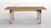
Multilayer-wood dining table
...er-wood dining table for download as blend, 3ds, fbx, and obj on turbosquid: 3d models for games, architecture, videos. (1546816)
3d_export
$16
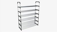
Multilayer Shoe Rack
...x 11.2" x 46.51"<br>- model parts: 14<br>- material count: 1<br>- xform: yes<br>- boxtrick: yes
3d_export
$25

mandala layer
... modelled in cinema 4d r23 hope you like it! also check out my other models, just click on my username to see a complete gallery.
3ddd
$1

Vintage kitchen props
...be aware: all of the shaders are set as multilayered blend materials; these materials may render slower than simple...
3ddd
free

Armchair/Ghost
...frame, with elastic belts, upholstered with polyurethane foams, removable covers. one back cushion in dacron and down 50 x 50 cm.
3ddd
$1

Pierre Paulin Leather and Steel Lounge Chair
...polak originals. detailed. be aware: shaders are set as multilayered vrayblend materials- these materials may render slower than simple...
3ddd
$1
RestartMilano Table lamp
... material:
1)base-only black
2)brass underneath through ao
3)full brass version
just adjust layer opacity to choose your version
3d_export
$90
skyscraper business center 145
...timized for vray<br>- smoothing modifier is stored in the stack for easy editing<br>- multilayer adobe phtoshop files
3d_export
$90
skyscraper business center 143
...timized for vray<br>- smoothing modifier is stored in the stack for easy editing<br>- adobe photoshop multilayer file
3d_export
$80

skyscraper business center 143
...timized for vray<br>- smoothing modifier is stored in the stack for easy editing<br>- multilayer adobe phtoshop files
Complement
turbosquid
$10

Poliform night complements
...orm chloe night complements for download as max, obj, and fbx on turbosquid: 3d models for games, architecture, videos. (1273828)
turbosquid
$7
Poliform Kelly NIGHT COMPLEMENT
...ree 3d model poliform kelly night complement for download as on turbosquid: 3d models for games, architecture, videos. (1577315)
3ddd
$1
Poliform Dream 684 night complements
...ments
3ddd
poliform , dream
poliform dream 684 night complements
with lamp, and painting
3d_export
$10

Complements chiave di violino 3D Model
...del
3dexport
complements chiave di violino molteni&c molteni
complements chiave di violino 3d model boroda 12690 3dexport
3d_export
$10

Complements chiave di violino 3D Model
...del
3dexport
complements chiave di violino molteni&c molteni
complements chiave di violino 3d model boroda 12691 3dexport
3ddd
$1
chair CH33
...chair ch33 3ddd the ch33 chair complement other...
3d_export
$5

hammer
...hammer is made in a pixel style, will perfectly complement your...
3d_export
$5
Armchair and pouf Teddi
...teddi 3dexport an armchair and an ottoman will perfectly complement your...
3d_export
$10

stump with moss
...stump with moss 3dexport low poly tree stump, complement your game...
3d_export
free

chicago tower model notex
...model notex 3dexport model is a great model to complement your urban...
Radial
3d_ocean
$5

Radial engine
...dial engine
3docean
engine radial
this is a radial engine used by the old airplanes. it is made in autodesk inventor and autocad.
3d_export
$5
radial engine
...ne , clearly shows how a radial engine works and all the parts present in it for a student or an engineer to have a glans on it .
3d_export
$5

shaft radial bearing
...shaft radial bearing
3dexport
shaft radial bearing
turbosquid
$7

Radial engine
...bosquid
royalty free 3d model radial engine for download as on turbosquid: 3d models for games, architecture, videos. (1672376)
turbosquid
$7
Radial Tyre
...osquid
royalty free 3d model radial tyre for download as max on turbosquid: 3d models for games, architecture, videos. (1433150)
turbosquid
$60

Radial engine
... available on turbo squid, the world's leading provider of digital 3d models for visualization, films, television, and games.
3d_export
$20

radial engine assembly
...radial engine assembly
3dexport
turbosquid
$4
Radial Hair Brush
... 3d model radial hair brush for download as max, obj, and fbx on turbosquid: 3d models for games, architecture, videos. (1183870)
turbosquid
$39

Wheel ATS Radial
... available on turbo squid, the world's leading provider of digital 3d models for visualization, films, television, and games.
turbosquid
$20
Radial Piston Assembly
... available on turbo squid, the world's leading provider of digital 3d models for visualization, films, television, and games.
Roller
turbosquid
$26
Roller A
...urbosquid
royalty free 3d model roller a for download as fbx on turbosquid: 3d models for games, architecture, videos. (1350603)
turbosquid
$3
Roller
...oyalty free 3d model roller for download as 3ds, max, and obj on turbosquid: 3d models for games, architecture, videos. (1460818)
3ddd
$1
edilkamin roller
...edilkamin roller
3ddd
камин
edilkamin roller 360
3ddd
$1
Roller Blinds
...roller blinds
3ddd
рулонная
roller blinds black out finish
turbosquid
$50
Roller
... roller for download as max, max, c4d, max, max, fbx, and obj on turbosquid: 3d models for games, architecture, videos. (1700762)
3d_export
$10
rollers
...lers
3dexport
this is low-poly model of rollers.<br>model:<br>- low-poly<br>- textured<br>- uv unwrapped
3d_export
$28
Roller 3D Model
...roller 3d model
3dexport
roller construction boss evil
roller 3d model adagio15740837 50561 3dexport
3d_export
$6
hopper roller conveyor
...hopper roller conveyor
3dexport
hopper roller conveyor
3d_export
$12
roller skates
...roller skates
3dexport
3d_ocean
$19
roller skate
...can scanned skates skating sport
3d scan of roller skate. the model has been retopologized and made fully compatible with zbrush.
Bearing
3d_export
$6
Bear
...bear
3dexport
bear
3d_export
$5
bearing
...bearing
3dexport
bearing
3d_export
$12
bear
...bear
3dexport
bear for 3d printing toy
3d_ocean
$9
Bearing
...ne ball ballbea bearing bearings engine hard industrial machine mechanic metal part piece plastic ring screw sphere steel
bearing
archibase_planet
free

Bear
...bear
archibase planet
statuette bear picturesque element
bear - 3d model (*.gsm+*.3ds) for interior 3d visualization.
3d_export
$5

bear
...bear
3dexport
bear have a stl.,3dm files
archibase_planet
free

Bear
...bear
archibase planet
bear animals omnivorous animal
bear angry n250907- 3d model (*.gsm+*.3ds) for interior 3d visualization.
archibase_planet
free

Bear
...bear
archibase planet
bear animals omnivorous animal
bear easy n250907 - 3d model (*.gsm+*.3ds) for interior 3d visualization.
3ddd
$1

Teddy bear
...teddy bear
3ddd
teddy bear , медведь
teddy bear :)
3d_ocean
$12
Bear
... formats. created with 3d max 9.0. this file is very useful for learning & rigging. it can be used for any professional work.
Full
3ddd
$1

Full Mobili
...ull mobili , шкаф
группа шкафов, серия мебели "классика" фабрики «full mobili»
turbosquid
$80
full man body+full facials
... available on turbo squid, the world's leading provider of digital 3d models for visualization, films, television, and games.
3ddd
$1
Full Mobili
...сика , стол
стол круглый офисный серия мебели "классика" фабрики «full mobili»
3ddd
$1
FULL MOBILI
... стол
cтол офисный серии мебели "классика" итальянской компании full mobili
design_connected
$16

Full Circle
...full circle
designconnected
atmosphere full circle computer generated 3d model.
3d_export
$5
full office
...full office
3dexport
this is full office cgi model created with maya -detailed -textured -uv mapped
design_connected
$16

Full Moon
...full moon
designconnected
roche bobois full moon computer generated 3d model. designed by ragot, cedric.
turbosquid
$100
FULL KITCHEN
...squid
royalty free 3d model full kitchen for download as skp on turbosquid: 3d models for games, architecture, videos. (1345817)
turbosquid
$15

Full Bedroomset
...id
royalty free 3d model full bedroomset for download as max on turbosquid: 3d models for games, architecture, videos. (1540649)
3d_export
$10
full human body
...full human body
3dexport
it is a full human sculpt