Thingiverse

Bondtech BMG Upper Mount for Ultibots D300VS by wesc
by Thingiverse
Last crawled date: 3 years ago
UPDATE: I've moved on to a Hemera mount for my D300VS. The cooling is much better with the new mount and allows printing overhangs and bridges much faster than with this mount. https://www.thingiverse.com/thing:4027625
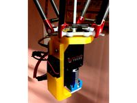
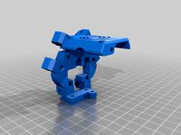
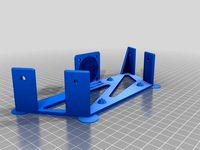
This is a BondTech BMG extruder mount for the Ultibots D300VS+ that sits above the effector plane, giving more Z printing height and also potentially minimizing acceleration wobble of the nozzle. This should work with SeeMeCNC Max printers or any other delta with a 50mm ball-ball spacing and using Tricklaser arms. The stock SeeMeCNC arms interfere with this mount. Hot end is a E3D V6. A Volcano should work as well.
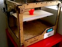
With this mount, I have over 500mm of build height on my D300VS+.
It will not work with the magball D300VS carriages as the ball spacing isn't right. If you upgrade to Tricklaser arms and appropriate carriages then it will work. (This is the best upgrade for D300VS, by far).
The Bondtech BMG is a really nice extruder. It is well designed and the dual driven hob pushes filament like no other.
There are 2 versions of this mount. One that uses ball studs and another that uses SeeMeCNC nylon barbells, and should work with the machined aluminum barbells available from SeeMeCNC.
The nylon barbells have a consistent ball-to-ball distance, but unfortunately, they flex quite a bit, leading to ringing on direction changes. With the metal balls I see about 1/2 the wavy ringing on direction changes.
Ball studs:https://www.ultibots.com/ball-studs-set-of-12-non-magnetic/
Nylon barbellshttps://www.seemecnc.com/collections/parts-accessories/products/replacement-ball-joints
Machined barbellshttps://www.seemecnc.com/collections/parts-accessories/products/cnc-machined-ball-joint-kit
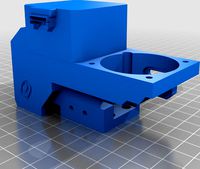
Cooling is performed by a 4020 blower fan. The fan is mounted above the stepper and body of the mount is the manifold. You can install up to 8 4mm aluminum tubes that descend from the effector base for part cooling. I have had good luck with 6 of them installed. Drill out the plugged holes with a 4mm bit for the tubes you wish to populate. Fix with a dab of CA adhesive The aluminum tubing is 4mm diam x 0.45 wall. I bought this via amazon, though it is out of stock now. Should be available at hobby stores.
https://www.amazon.com/gp/product/B005WPAJUE/ref=oh_aui_search_detailpage?ie=UTF8&psc=1
Print the mandrel and roller parts and bend the aluminum tubing. It may require some sanding, tweaking, pinching and cutting to get the aluminum shaped correctly. Press them into the drilled holes on the bottom of the effector and optionally secure with some CA adhesive.
Copper or brass should also work. Stainless (available from mcmaster.com) is too hard to easily bend, though you may have better luck packing the tube with sand or using a torch to bend.
This design requires a 20mm thick pancake Nema17 stepper. A 25mm thick might work, but it may interfere with the Z column arms. 20mm stepper at 800mA & 24V works just fine and doesn't skip steps. I got mine from steppers online:
https://www.omc-stepperonline.com/hybrid-stepper-motor/nema-17-bipolar-18deg-13ncm-184ozin-1a-35v-42x42x20mm-4-wires-17hs08-1004s.html
There is provision for a 2mm dia rod to function as a strain relief mast for the wires leading to the effector. Drill that out if necessary.
Note, that to get things to not interfere, I had to move the nozzle 20mm forwards of the centerpoint. This wlll slightly reduce the print area. If using Duet3D, add the following to your config.g file:
G10 P0 X0 Y-20 ; for offset BMG extruder
Here's all my config changes for this:
M92 E421 ; From motor calibration via mhackneys calibration tool. Your's may be different
M906 X1000 Y1000 Z1000 E800 ; Bondtech set motor currents to 800mA for 20mm pancake (mA)
G10 P0 X0 Y-20 ; BMG Upper has nozzle 20mm offset. Compensate for that. (edited)
M665 L374.810 R204.934 H514.769 B140.0 X-0.073 Y-0.237 Z0.000
M558 P4 X0 Y0 Z0 H50 I1 ; FSRs with JohnSL board Z probe behaves as a switch and is not used for homing any axes
You will also need to edit homedelta.g to lower the carriages down a bit so the 20mm offset can be accomplished without bumping the endstops.
Change the G1 Z-XX line to:
G1 Z-15 F2000 ; down a few mm so that we can centre the head
; Change "H25" to "H3" AFTER commissioning your printer
Run through step 84 of the D300VS build guide. Once M665 values have been found, replace them in config.sys and you may reduce the H50 in the M558 command to H5 (I have it set at H3 for even faster bed probing)
calibration tool:https://www.thingiverse.com/thing:2598993
Finally, slice this with Slic3r PE using the "Support on Build Plate Only" checkbox selected in the Support Material tab. This prevents it from infilling the manifolds with support material. Also uncheck Support Bridges. I haven't found a way to do the same in KissSlicer.
This is a BondTech BMG extruder mount for the Ultibots D300VS+ that sits above the effector plane, giving more Z printing height and also potentially minimizing acceleration wobble of the nozzle. This should work with SeeMeCNC Max printers or any other delta with a 50mm ball-ball spacing and using Tricklaser arms. The stock SeeMeCNC arms interfere with this mount. Hot end is a E3D V6. A Volcano should work as well.
With this mount, I have over 500mm of build height on my D300VS+.
It will not work with the magball D300VS carriages as the ball spacing isn't right. If you upgrade to Tricklaser arms and appropriate carriages then it will work. (This is the best upgrade for D300VS, by far).
The Bondtech BMG is a really nice extruder. It is well designed and the dual driven hob pushes filament like no other.
There are 2 versions of this mount. One that uses ball studs and another that uses SeeMeCNC nylon barbells, and should work with the machined aluminum barbells available from SeeMeCNC.
The nylon barbells have a consistent ball-to-ball distance, but unfortunately, they flex quite a bit, leading to ringing on direction changes. With the metal balls I see about 1/2 the wavy ringing on direction changes.
Ball studs:https://www.ultibots.com/ball-studs-set-of-12-non-magnetic/
Nylon barbellshttps://www.seemecnc.com/collections/parts-accessories/products/replacement-ball-joints
Machined barbellshttps://www.seemecnc.com/collections/parts-accessories/products/cnc-machined-ball-joint-kit
Cooling is performed by a 4020 blower fan. The fan is mounted above the stepper and body of the mount is the manifold. You can install up to 8 4mm aluminum tubes that descend from the effector base for part cooling. I have had good luck with 6 of them installed. Drill out the plugged holes with a 4mm bit for the tubes you wish to populate. Fix with a dab of CA adhesive The aluminum tubing is 4mm diam x 0.45 wall. I bought this via amazon, though it is out of stock now. Should be available at hobby stores.
https://www.amazon.com/gp/product/B005WPAJUE/ref=oh_aui_search_detailpage?ie=UTF8&psc=1
Print the mandrel and roller parts and bend the aluminum tubing. It may require some sanding, tweaking, pinching and cutting to get the aluminum shaped correctly. Press them into the drilled holes on the bottom of the effector and optionally secure with some CA adhesive.
Copper or brass should also work. Stainless (available from mcmaster.com) is too hard to easily bend, though you may have better luck packing the tube with sand or using a torch to bend.
This design requires a 20mm thick pancake Nema17 stepper. A 25mm thick might work, but it may interfere with the Z column arms. 20mm stepper at 800mA & 24V works just fine and doesn't skip steps. I got mine from steppers online:
https://www.omc-stepperonline.com/hybrid-stepper-motor/nema-17-bipolar-18deg-13ncm-184ozin-1a-35v-42x42x20mm-4-wires-17hs08-1004s.html
There is provision for a 2mm dia rod to function as a strain relief mast for the wires leading to the effector. Drill that out if necessary.
Note, that to get things to not interfere, I had to move the nozzle 20mm forwards of the centerpoint. This wlll slightly reduce the print area. If using Duet3D, add the following to your config.g file:
G10 P0 X0 Y-20 ; for offset BMG extruder
Here's all my config changes for this:
M92 E421 ; From motor calibration via mhackneys calibration tool. Your's may be different
M906 X1000 Y1000 Z1000 E800 ; Bondtech set motor currents to 800mA for 20mm pancake (mA)
G10 P0 X0 Y-20 ; BMG Upper has nozzle 20mm offset. Compensate for that. (edited)
M665 L374.810 R204.934 H514.769 B140.0 X-0.073 Y-0.237 Z0.000
M558 P4 X0 Y0 Z0 H50 I1 ; FSRs with JohnSL board Z probe behaves as a switch and is not used for homing any axes
You will also need to edit homedelta.g to lower the carriages down a bit so the 20mm offset can be accomplished without bumping the endstops.
Change the G1 Z-XX line to:
G1 Z-15 F2000 ; down a few mm so that we can centre the head
; Change "H25" to "H3" AFTER commissioning your printer
Run through step 84 of the D300VS build guide. Once M665 values have been found, replace them in config.sys and you may reduce the H50 in the M558 command to H5 (I have it set at H3 for even faster bed probing)
calibration tool:https://www.thingiverse.com/thing:2598993
Finally, slice this with Slic3r PE using the "Support on Build Plate Only" checkbox selected in the Support Material tab. This prevents it from infilling the manifolds with support material. Also uncheck Support Bridges. I haven't found a way to do the same in KissSlicer.
Similar models
thingiverse
free

CR-10 Better Bondtech BMG Mount by int2str
...(not a remix, designed from scratch in openscad)that has the same 90deg layout of the bondtech mount and has no clearance issues.
thingiverse
free
Bondtech BGM Mount for Rostock MAX by SublimeLayers
...gn shown in the photos above. it is not included here. here's the link to the tusk: https://www.thingiverse.com/thing:2445660
thingiverse
free

2020 Extruder Duel Mount V1.0 by dbfrompw
.... designed to work with the ezr struder from seemecnc. https://www.seemecnc.com/collections/parts-accessories/products/ezrstruder
thingiverse
free

SeeMeCNC H-1.1 Z endstop mount by nyl0cke
... also work for the h-1 and any other printer that uses 1/4" rods for the z guides. should print off fine in both pla and abs
thingiverse
free

MGN12 SeeMeCNC Barbell Carriage for Delta Printer (D300VS and others)
...ails when mounting them.
also check out my hemera mount that also uses seemecnc barbellshttps://www.thingiverse.com/thing:4027625
thingiverse
free

E3D Aero Mount for D300VS and E3D Volcano by somewhat_brave
...1.19 b140 h434.44 x-0.0 y-0.0 z0.00 ;original line
m665 r203.58 l361.19 b140 h477.8 x-0.0 y-0.0 z0.00 ; new line
thingiverse
free

Wanhao Di3 Plus mount for E3D v6 Bondtech BMG by Burnt_Toast
...inted this at 100% infill in both petg and nylon and both perform great. endstop and control board mounts as originally designed.
thingiverse
free
mount for bmg extruder Ender 3 by small_tornado
...res. i made a simple mount for the motor and extruder bmg.
note: file "mount-6.stl" need to rotate 90 degree in slicer.
thingiverse
free

Anycubic Predator BMG to stepper motor - flying style mount by Ojref
...nd a washer for fasteners. i printed mine in pctg (polycarbonate-petg blend) however asa or petg should be adequate for the task.
thingiverse
free

2020 Extrusion Mount for Bondtech BMG Extruder by adrianm1972
...2020 extrusion mount for bondtech bmg extruder by adrianm1972
thingiverse
this is a mount for the bondtech bmg extruder.
Wesc
3ddd
$1

Wesc - Oboe Headphones
...oe headphones
3ddd
наушники
wesc oboe headphones.
high detail, all colors in the preview image are included inside the .mat file.
turbosquid
$30

WESC Headphones | C4D and FBX
... available on turbo squid, the world's leading provider of digital 3d models for visualization, films, television, and games.
3d_export
$5

Stereo Headphones 3D Model
...stereo radio dre phones bluetooth muffs music ipod discman wesc stereo headphones 3d model benhurst 75663...
3d_sky
$8

Wesc - Oboe Headphones
...sc - oboe headphones
3dsky
wesc oboe headphones.
high detail, all colors in the preview image are included inside the .mat file.
thingiverse
free

Everdrip Dehumidifier by wesc
...i_search_detailpage?ie=utf8&psc=1
update: added sketchup file if you wish to modify, perhaps to attach a hose to the output.
thingiverse
free
Curad Alcohol Prep Pad Holder by wesc
...om is vented so bits of plastic don't accumulate in the holder.
curad pads are available at costco.
fusion 360 file included.
thingiverse
free

Octopus Phone Stand with Pockets for Magnets by wesc
...ertigo grey (great at hiding layer lines)
see my other tentacled thingsoctopus coffee bean hopper standoctopus tentacle belt rack
thingiverse
free
DtM-v3.0 Face Shield Smoother Faster Remix by wesc
...ed is prusaslicer .3mf file with settings that enable me to print these in about 55 minutes using a printer with volcano hot end.
thingiverse
free

Improved Slice Mosquito Groovemount Adapters by wesc
...part# 94180a307
heat-set inserts for plastics, m2 x 0.4 mm thread size, 2.9 mm installed length.
fusion360 file uploaded as well.
thingiverse
free

DePRUSAfied Protective Face Shield - RC2 by wesc
...s
we need rc2 of both band pieces in the model here preferably in petg (best for disinfecting) but will take any labeled material
D300Vs
thingiverse
free
E3D Hemera delta mount (D300VS/D300VS+)
...rest is as the original. print upside down with support. and don't look at my wiring, it was only mounted for a short test ;)
thingiverse
free

D300vs cable guide by stavrosg
...ade one for my cr-10, adapted it for my delta ,an ultibots d300vs+
added a 60mm taller version that handled my 450mm delta better
thingiverse
free

D300VS+ Dust Covers by Lucidwolf
...vertical slot based delta printers.
this is part of my upgrades to the ultibots d300vs+ https://www.thingiverse.com/thing:3089764
thingiverse
free

D300VS+ Modifications by Lucidwolf
...printers speed limit.
like most printers this is a work in progress.
still need to design and print
1.) led holders
2.) enclosure
thingiverse
free

D300VS Directed Airflow Part Cooler by hardrocker
...mm blower fans with no changes required for the wiring. the design requires (6) m3x25mm screws and (6) m3 nuts for installation.
thingiverse
free

D300VS Thickened Barbell Carriages
...them to work.
another good mod would be to move the tensioning mechanism over to the side with the two wheels for more stability.
thingiverse
free

UltiBots D300VS Filament Guide by SublimeLayers
...imelayers
thingiverse
this is a filament guide that helps prevent filament from unspooling when the printer homes after a print.
thingiverse
free

55mm Magball Carriage & Effector for D300VS+
... of the effector in order to allow easier access to the titan aero (or titan extruder.) this makes assembly and cleaning easier.
thingiverse
free

UltiBots D300VS 3D Printer by Verohomie
...
d300vs bom is located here https://docs.google.com/spreadsheets/d/13qilrma5xjv6fmad4rimuzotkzjiyf5niunzzmn20gm/edit?usp=sharing
thingiverse
free
Tusk Fan for D300VS+ magball edition
...erse.com/thing:2223113/ effector :)
source here https://www.sublimelayers.com/2017/10/tusk-part-cooling-for-titan-aero-and.html
Ultibots
thingiverse
free
Power plate for K250 from Ultibots by kdupke
...power plate for k250 from ultibots by kdupke
thingiverse
a power plate for the k250 from ultibots.
thingiverse
free

Connector/voltmeter panel for Ultibots Kossel 250V by nlbrewe
...voltmeter panel for ultibots kossel 250v by nlbrewe
thingiverse
connector and voltmeter mounting panel for ultibots kossel 250v
thingiverse
free

Ultibots 24v-to-12v converter mount by Verohomie
...verse
ultibots 24v-to-12v converter mount.
mendelmax 1.5+ kits and printed parts are available for purchase at www.ultibots.com.
thingiverse
free
Ultibot by stefan787
...st is around 400 euro, it can be a bit cheaper. i used really good electronics, form pibot.
check them out:
http://pibot.com/
thingiverse
free

UltiBots K250 XT-60 Panel Mount by ewingate
...0 xt-60 panel mount by ewingate
thingiverse
this part holds an xt-60 connector to the lower frame of the ultibots k250 (or bse).
thingiverse
free

Huntley Effector remixed for Ultibots extruder by frdstang93
...agnetic effector for use with the ultibots micro extruder. i also configured it to use a piece of ptfe tube as a filament guide.
thingiverse
free
Electronic mount for K250 from Ultibots by kdupke
...e k250 from ultibots.
the original one is well designed but stabs into the stand of the k250 not leaving room for other mounts.
thingiverse
free

Duct for Ultibots K250VS-BSE by Viald
... the hot bed (see picture)
this duct can be mount only to the lasted extruder body which uses 2 screws to fix the hot head.
enjoy
thingiverse
free

NAZA mount Ultibot Discovery Pro Endurance by SBS_FPV
...scovery pro endurance fly... lets make it fly...
here is a dji naza mount that will soon fit to the origanal design by steafn787.
thingiverse
free
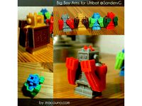
Big Boy Arms for Ultibot @SandervG by macouno
...like this by request. if you would like me to create and share something just let me know and if i have the time i might make it!
Bondtech
thingiverse
free

x5s bondtech
...x5s bondtech
thingiverse
this allow using a bondtech dual drive on x5s machines
thingiverse
free

Bondtech mount by Nicoande99
...bondtech mount by nicoande99
thingiverse
custom bondtech mount for my velleman k8200 3d printer.
thingiverse
free

Trex2+ Bondtech adpter by fong504
...trex2+ bondtech adpter by fong504
thingiverse
bondtech makerbot 2 clone adapter for the trex2+.
thingiverse
free

Bondtech PTFE tube Holder
...bondtech ptfe tube holder
thingiverse
adjusted a bit to fit my bondtech clone.
thingiverse
free
Bondtech DDX by sebbzor
...of the ddx incase you want to build adapters for it. original stepfile can be found on bondtechs website, all credits go to them.
thingiverse
free

Support BONDTECH Anet_A8 By SergioFPV by SergioFPV
...support bondtech anet_a8 by sergiofpv by sergiofpv
thingiverse
support bondtech anet_a8
thingiverse
free

CR-10S-Bondtech-Mosquito_Mount_Bl_Touch by enoblk
...cr-10s-bondtech-mosquito_mount_bl_touch by enoblk
thingiverse
cr-10s-bondtech-mosquitomount-_bl_touch
thingiverse
free

Bondtech Flying mount by Yakandu
...du
thingiverse
lightweight flying extruder mount for the bondtech bmg with design centred around filament path.
this is a remix.
thingiverse
free

Bondtech Oiler by bamhm182
...t a piece of sponge and put it in the hole. oil it up and you're good to go! been using it for a few months with no problems.
thingiverse
free

RatRig V-Core Pro Bondtech Carriage (Prusa MK3S Bondtech Extruder)
...dtech can be mounted 1:1 :)
i have the mk3s with bondtech and mosquito magnum. i'll try out if my ratrig arrives...
have fun!
Bmg
turbosquid
$3

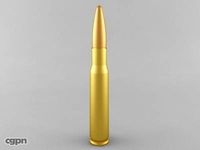
.50 BMG
... available on turbo squid, the world's leading provider of digital 3d models for visualization, films, television, and games.
turbosquid
$2

.50 BMG
... available on turbo squid, the world's leading provider of digital 3d models for visualization, films, television, and games.
turbosquid
$30

Sniper 50 bmg
... available on turbo squid, the world's leading provider of digital 3d models for visualization, films, television, and games.
turbosquid
free

Cal 50 BMG
... available on turbo squid, the world's leading provider of digital 3d models for visualization, films, television, and games.
cg_studio
$25
.50 BMG Cartridge3d model
...odel
cgstudio
.3ds .max .obj .wrl - .50 bmg cartridge 3d model, royalty free license available, instant download after purchase.
3d_export
$5
50 caliber BMG round 3D Model
...d 3d model
3dexport
50cal caliber 50 round bullet bmg cartridge browning rifle
50 caliber bmg round 3d model csw92 27660 3dexport
3d_export
$22
.50 BMG Cartridge 3D Model
...ectile rifle round pistol cartridge m2 hb 127x99mm nato browning barrett m82a1
.50 bmg cartridge 3d model plutonius 8091 3dexport
turbosquid
free
LAR Grizzly .50 BMG Sniper
... available on turbo squid, the world's leading provider of digital 3d models for visualization, films, television, and games.
3d_export
$8
cartrige m50 bmg
...aterials are logically named<br>the main format is in 3ds max 2009.<br>satisfcation garranteed..<br>thank you !
3d_export
$30
Sniper 50bmg 3D Model
...sniper 50bmg 3d model
3dexport
sniper 50 bmg
this zip file include sniper 50bmg modo ,lightwave,obj,fbx
Upper
3d_export
$19

Upper ab machine
...upper ab machine
3dexport
turbosquid
free

Upper and Lower Teeth
...ree 3d model upper and lower teeth for download as ma and obj on turbosquid: 3d models for games, architecture, videos. (1636970)
turbosquid
$18

Upper Lateral Incisor
... available on turbo squid, the world's leading provider of digital 3d models for visualization, films, television, and games.
turbosquid
$2

Male Upper Body
... available on turbo squid, the world's leading provider of digital 3d models for visualization, films, television, and games.
turbosquid
free

Upper Kitchen Wardrobe
... available on turbo squid, the world's leading provider of digital 3d models for visualization, films, television, and games.
3d_export
$10
set of upper kitchen modules
...t of standard upper kitchen modules, according to real working dimensions. there are few accessories, such as hinges and awnings.
turbosquid
$2

modeling the upper part of a robot
... 3d model modeling the upper part of a robot for download as on turbosquid: 3d models for games, architecture, videos. (1672422)
turbosquid
$49

Upper First Left Bicuspid
...model upper first left bicuspid for download as blend and obj on turbosquid: 3d models for games, architecture, videos. (1281409)
turbosquid
$49

Upper First Left Molar
...3d model upper first left molar for download as blend and obj on turbosquid: 3d models for games, architecture, videos. (1249395)
turbosquid
$7

OUTDOOR UPPER BODY TRAINER
... outdoor upper body trainer for download as max, obj, and fbx on turbosquid: 3d models for games, architecture, videos. (1464527)
Mount
3d_export
free

mounting bracket
...mounting plate is the portion of a hinge that attaches to the wood. mounting plates can be used indoors, cabinetry and furniture.
turbosquid
$2

MOUNTING
... available on turbo squid, the world's leading provider of digital 3d models for visualization, films, television, and games.
turbosquid
free

Mounts
... available on turbo squid, the world's leading provider of digital 3d models for visualization, films, television, and games.
turbosquid
free

Mount Fuji
...fuji
turbosquid
free 3d model mount fuji for download as obj on turbosquid: 3d models for games, architecture, videos. (1579977)
3d_export
$5

Headphone mount LR
...headphone mount lr
3dexport
headphone mount l+r
turbosquid
$39

Mount rainier
...quid
royalty free 3d model mount rainier for download as fbx on turbosquid: 3d models for games, architecture, videos. (1492586)
turbosquid
$5

pipe mounting
...quid
royalty free 3d model pipe mounting for download as obj on turbosquid: 3d models for games, architecture, videos. (1293744)
3d_export
$5

Magnetic GoPro Mount
...pro mount
3dexport
cool magnetic mount for gopro. allows you to mount the camera on flat metal surfaces and get exclusive shots.
turbosquid
$5

Stone Mount
...ty free 3d model stone mount for download as ma, obj, and fbx on turbosquid: 3d models for games, architecture, videos. (1370306)
3ddd
$1
Wall Mounted Basin
...wall mounted basin
3ddd
high detailed wall mounted basin
material included