Thingiverse
Boitier ventilé RAMPS Arduino LCD12864 / LCD12864 Arduino RAMPS case with fan by CherHubert
by Thingiverse
Last crawled date: 3 years, 1 month ago
--- Videos ---
Impression / Print : https://youtu.be/3JqaZjaI6h4
Assemblage / Assembly : https://youtu.be/cKQOOUaG2FM
--- Français (English below) ---
Mise à jour du 04/09/2019 : Ultime version ici
Mise à jour du 16/05/2018 : Nouvelle version ici
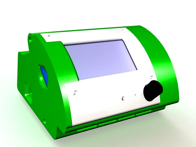
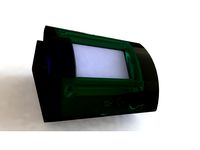
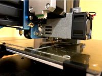
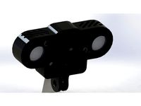
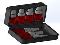
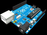
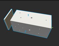
Voici la version avec ventilateur de mon boitier de commande d'imprimante 3D. A l’intérieur se logent : carte Arduino + RAMPS1.4 + écran LCD 12864 + deux ventilateurs 25x25x10 (max 25x25x15) + un ventilateur 40x40x10.
NB : Toutes les pièces sont conçues pour être imprimées sans support matériel (les supports nécessaires sont intégrés au design)
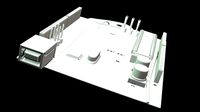
L'assemblage compte trois pièces imprimées :
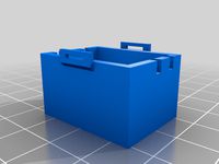
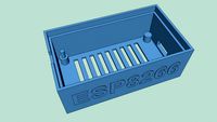
le corps principal
un panneau latéral
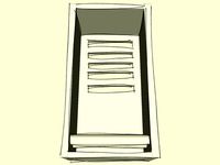
un capot pour l'écran LCD
Quincaillerie :
4 vis M3x20
2 vis M3x25 (ou M3x30)
1 connecteur électrique femelle 2,1 x 5,5 mm
Préparation
Imprimez et nettoyez les trois pièces
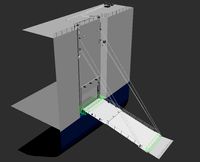
Supprimez les supports d'impression du panneau latéral :
Passage prise USB + passage carte SD
Emplacement connecteur électrique
Supprimez les supports du capot écran :
Passage bouton
Vérifiez que tout s’emboîte correctement
Assemblage
(Regardez la vidéo d'assemblage : lien en début d'article)
Fixez les ventilateurs 25x25x10 avec des vis M2,5x16. Une vis par ventilateur suffit.
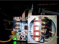
Branchez les deux câbles de l'écran LCD sur la carte RAMPS uniquement.
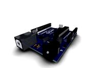
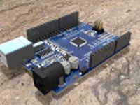
Glissez les cartes Arduino et RAMPS préalablement câblées dans le boitier.
Attachez les câbles (et la gaine si vous en mettez une) en utilisant un collier plastique.
Glissez le ventilateur 40x40x10 dans son logement.
Montez le connecteur d'alimentation électrique femelle 2.1 x 5.5 sur le capot latéral
Branchez les câbles du ventilateur et de l'alimentation sur le bornier.
Mettez l'écran LCD en place
Placez son capot dessus et fixez-le avec une vis M3x20 en haut et une vis M3x25 en bas
Mettez le capot latéral en place et fixez-le à l'aide des trois vis M3x20 et la vis M3x25 restante qui se place au bas à gauche du capot d'écran.
Et voilà, c'est fini !
Alors, heureux ? ;)
--- English ---
Update 2019/09/04 : Ultimate version here
Update 2018/05/16 : New version here
Here is the version of my 3D printer control case with fan. Inside are housed : arduino card + RAMPS1.4 + LCD 12864 + two fans 25x25x10 (max 25x25x15) + one fan 40x40x10.
NB : Parts are designed to be printed without material support.
The assembly consists of three printed parts :
the main body
a side panel
a LCD frame
Hardware:
4 screw M3x20
2 screw M3x25 ou M3x30
1 female electrical connector 2,1 x 5,5 mm
Prep
Print and clean the three parts
Remove the printing supprts from the side panel :
USB plug and SD card passages
Electrical connector location
Remove the printing support from the LCD frame
Button passage
4 - Check that everything fits properly
Assembly
(Watch the assembly video : link at the beginning of the article)
Fix fans 25x25x10 with M2,5x16 screws.One screw by fan is enough.
Connect the two cables of the LCD on the RAMPS board only.
Slide the Arduino and RAMPS cards previously wired into the case
Clamp the cables (and sheath) using a plastic tie
Slide the fan 40x40x10 into place.
Mount the female electrical power connector 2.1 x 5.5 on the side panel
Connect the fan and the power connector on the power terminal block
Put the LCD in place
Place the LCD frame and fix it with one M3x20 screws at the top and one M3x25 screw downstairs
Put the side cover and fasten it with three screws M3x20 and one screw M3x25 which is placed at the bottom left of the LCD frame.
and that's it!
So, happy? ;)
Impression / Print : https://youtu.be/3JqaZjaI6h4
Assemblage / Assembly : https://youtu.be/cKQOOUaG2FM
--- Français (English below) ---
Mise à jour du 04/09/2019 : Ultime version ici
Mise à jour du 16/05/2018 : Nouvelle version ici
Voici la version avec ventilateur de mon boitier de commande d'imprimante 3D. A l’intérieur se logent : carte Arduino + RAMPS1.4 + écran LCD 12864 + deux ventilateurs 25x25x10 (max 25x25x15) + un ventilateur 40x40x10.
NB : Toutes les pièces sont conçues pour être imprimées sans support matériel (les supports nécessaires sont intégrés au design)
L'assemblage compte trois pièces imprimées :
le corps principal
un panneau latéral
un capot pour l'écran LCD
Quincaillerie :
4 vis M3x20
2 vis M3x25 (ou M3x30)
1 connecteur électrique femelle 2,1 x 5,5 mm
Préparation
Imprimez et nettoyez les trois pièces
Supprimez les supports d'impression du panneau latéral :
Passage prise USB + passage carte SD
Emplacement connecteur électrique
Supprimez les supports du capot écran :
Passage bouton
Vérifiez que tout s’emboîte correctement
Assemblage
(Regardez la vidéo d'assemblage : lien en début d'article)
Fixez les ventilateurs 25x25x10 avec des vis M2,5x16. Une vis par ventilateur suffit.
Branchez les deux câbles de l'écran LCD sur la carte RAMPS uniquement.
Glissez les cartes Arduino et RAMPS préalablement câblées dans le boitier.
Attachez les câbles (et la gaine si vous en mettez une) en utilisant un collier plastique.
Glissez le ventilateur 40x40x10 dans son logement.
Montez le connecteur d'alimentation électrique femelle 2.1 x 5.5 sur le capot latéral
Branchez les câbles du ventilateur et de l'alimentation sur le bornier.
Mettez l'écran LCD en place
Placez son capot dessus et fixez-le avec une vis M3x20 en haut et une vis M3x25 en bas
Mettez le capot latéral en place et fixez-le à l'aide des trois vis M3x20 et la vis M3x25 restante qui se place au bas à gauche du capot d'écran.
Et voilà, c'est fini !
Alors, heureux ? ;)
--- English ---
Update 2019/09/04 : Ultimate version here
Update 2018/05/16 : New version here
Here is the version of my 3D printer control case with fan. Inside are housed : arduino card + RAMPS1.4 + LCD 12864 + two fans 25x25x10 (max 25x25x15) + one fan 40x40x10.
NB : Parts are designed to be printed without material support.
The assembly consists of three printed parts :
the main body
a side panel
a LCD frame
Hardware:
4 screw M3x20
2 screw M3x25 ou M3x30
1 female electrical connector 2,1 x 5,5 mm
Prep
Print and clean the three parts
Remove the printing supprts from the side panel :
USB plug and SD card passages
Electrical connector location
Remove the printing support from the LCD frame
Button passage
4 - Check that everything fits properly
Assembly
(Watch the assembly video : link at the beginning of the article)
Fix fans 25x25x10 with M2,5x16 screws.One screw by fan is enough.
Connect the two cables of the LCD on the RAMPS board only.
Slide the Arduino and RAMPS cards previously wired into the case
Clamp the cables (and sheath) using a plastic tie
Slide the fan 40x40x10 into place.
Mount the female electrical power connector 2.1 x 5.5 on the side panel
Connect the fan and the power connector on the power terminal block
Put the LCD in place
Place the LCD frame and fix it with one M3x20 screws at the top and one M3x25 screw downstairs
Put the side cover and fasten it with three screws M3x20 and one screw M3x25 which is placed at the bottom left of the LCD frame.
and that's it!
So, happy? ;)
Similar models
thingiverse
free
Boitier ventilé v3 RAMPS Arduino LCD12864 / LCD12864 Arduino RAMPS case with fan v3 by CherHubert
...ttom left of the display cover..
and that's it!
don't forget to post a photo of your realization, it's always nice :)
thingiverse
free

Boitier RAMPS Arduino LCD12864 / RAMPS Arduino LCD12864 case by CherHubert
...aining screws, the longest going into the hole next to the button of the lcd monitor
and voilà, c'est fini !
so, happy ? ;)
thingiverse
free

Arduino 2560 adapter for PC power supply box by Madlulla
...sa ramp dans une boite d'alim pc hs. on profite du ventilateur pour refroidir les transistors de puissance et les stepsticks.
thingiverse
free
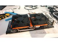
MSI ARMOR Cooling Mod (RX 580 8GB) by Hathek
... le support sur le radiateur
placez 2 ventilateurs de 92 mm alignés avec leurs trous respectifs et fixez-les à l'aide rilsans
thingiverse
free

PM Tornado extruder fan kit by Papa_Marco
...careful when tightening. do not squeeze too hard. for those who wish to tighten hard, change the screws and put washers and nuts.
thingiverse
free
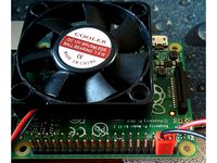
Connecteur de ventilateur pour Raspberry Pi / Fan connector by Aklain52
...ontact efficace.
les ventilateurs 12v tournent moins vite en 5v mais cela est largement suffisant pour refroidir le raspberry pi.
thingiverse
free

Duct Fan turbine by VINCE27M
... turbine by vince27m
thingiverse
voici une remix du support de ventilateur latéral pour l'utilisation sur une microdelta diy
thingiverse
free
Fan bracket Sovol SV01 + fan duct by Negimex
...pport for fans + fan duct for sovol sv01 printer. allows the mounting of a 40 mm fan on the front and a 50x15 mm fan on the side.
thingiverse
free

cr-10s-pro fan duct plc
...uct plc
thingiverse
fan duct pour cr-10s pro. montage en lieu et place du ventilateur existant mais avec fixation par les 3 vis.
thingiverse
free

Arduino + Ramp 1.4 + LCD by Stef26
...duino + la carte ramp 1.4 et le connecteur lcd
vous avez toujours accès au bouton reset.
il peut se fixer sur un profilé de 30x30
Ventilé
thingiverse
free

Frein à disque ventilé by mafia_7140
...adapter directement sur votre voiture thermique ou électrique.
accessoires de tunning qui peut être sympa dans le monde rc drift.
thingiverse
free

Capot ventilé 5010 pour fermer le boitier de La Trigorilla by michauddepau
...0 pour fermer le boitier de la trigorilla by michauddepau
thingiverse
capot ventilé 5010 pour fermer le boitier de la trigorilla
thingiverse
free

Boitier ventilé pour Raspberry Pi 3 (case) by Aklain52
...qui peut être alimenté par les pins du raspberry pi.
un connecteur est disponible ici : https://www.thingiverse.com/thing:2568001
thingiverse
free

Boitier ventilé adaptation connecteur centronics 50 by Ma-Team-3D
...74437952887826/)
if you do not have the means to model, modify or create, please contact me on the facebook page mentioned above.
thingiverse
free
Motors protects with cooling for 22** / 23** / 24** (2 types of design) by bilou02130
...(2 types of design) by bilou02130 thingiverse protection moteur ventilé 22 / 23 / 24** (2205....2306....2408....) motor protect with...
thingiverse
free

Support bowden Prusa i3 Hephestos by Jpg32190
...adaptable aux i3 reworks a faire : ajouter les ventilé pour refroidir...
thingiverse
free

Support CM Alfawise U20 by Bidouille85
...conçu afin de l'intégrer dans un caisson insonorisé et ventilé pour mettre mon...
thingiverse
free
Boitier ventilé v3 RAMPS Arduino LCD12864 / LCD12864 Arduino RAMPS case with fan v3 by CherHubert
...ttom left of the display cover..
and that's it!
don't forget to post a photo of your realization, it's always nice :)
thingiverse
free
Support GT2560 Rev A+ / pour CR10 by Hercule_W
...souhaiterait abaisser son signal à 5v. le tous est ventilé par un ventilo dimension 80-80-15. j'ai utilisé de la...
Cherhubert
thingiverse
free
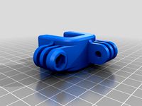
Petit serre-joint GoPro by CherHubert
...petit serre-joint gopro by cherhubert
thingiverse
mini serre-joint avec montages types gopro
mini clamp with gopro fixtures
thingiverse
free

GoPro HERO 2 Frame by CherHubert
...e
fr : boîtier conçues pour être imprimées sans supports matériels.
en : frame designed to be printed without material supports.
thingiverse
free

Poignée imitation volant en fonte by CherHubert
...née de meuble et bouton d'autoradio imitation volant en fonte.
modélisé avec fusion 360, source ici : https://a360.co/2vqg3xe
thingiverse
free

CHACRAS (CherHubert Amazing Case for Ramps-Arduino-Screen) for Lowrider2 Y mounting by WrightWells
...2 y mounting by wrightwells
thingiverse
changes location of the power input and adds holes to allow fitting to the y plate bolts
thingiverse
free

Support casque / helmet holder by CherHubert
...h :
variable tilt motorcycle helmet wall mount.
you will need a 6mm diameter threaded rod and two nuts to assemble the two parts.
thingiverse
free

Toupie - Fidget hand spinner by CherHubert
...:
1 x fidget spinner-corps.stl printed
2 x fidget spinner-bouton.stl printed
1 x 625 ball bearing (d16 d5 e5)
5 x balls about d16
thingiverse
free
Boitier Camera Pi V2 avec Leds IR by CherHubert
...v2 équipée de leds infrarouges.
si vous êtes aussi intéressé par le serre-joint de plateau qui se trouve sur la photo, il est ici
thingiverse
free

Support flechettes / Dart holder by CherHubert
...he photos), the darts are very close to each other, the center distance is 17.5mm
3x5, more spaced with a center distance of 20mm
thingiverse
free

Support écran / monitor stand by CherHubert
...pport dimension : 260x182 outside 204x123 inside, 100mm height
print duration : 32h33 with a 0.5mm nozzle and 0.3mm layers height
thingiverse
free

Toupie - Fidget hand spinner by CherHubert
....stl printed
2 x spinner-bouton.stl printed
1 x 625 ball bearing (d16 d5 e5)
2 x balls about d16
the black part was bomb-painted.
Lcd12864
thingiverse
free

LCD12864 Fusion360 by Muffin256
...lcd12864 fusion360 by muffin256
thingiverse
lcd12864
thingiverse
free

Anet A8 LCD12864 support by jjavellaneda
...anet a8 lcd12864 support by jjavellaneda
thingiverse
anet a8 lcd12864 support
thingiverse
free

Anet A8 LCD12864 with tags by Shojo
...anet a8 lcd12864 with tags by shojo
thingiverse
anet a8 lcd12864 with tags
thingiverse
free

Сase LCD12864 by VitaliySh
...сase lcd12864 by vitaliysh
thingiverse
no rear cover. later i will add.
thingiverse
free

LCD12864 case + Raspberry Pi 3 by komandr
...lcd12864 case + raspberry pi 3 by komandr
thingiverse
lcd12864 case + raspberry pi 3(4)
thingiverse
free

Geeetech LCD12864 Smart Controller frame by mrzed
...https://www.geeetech.com/reprap-smart-controller-lcd12864-version-led-turn-on-control-p-690.html?zenid=j6jskj4m73hcidra5srau49hi2
thingiverse
free

Anet A8 LCD12864 by Muffin256
...anet a8 lcd12864 by muffin256
thingiverse
anet a8 lcd12854
thingiverse
free

LCD12864 hexagonic mount by 4ndreas
...2864 grafic display.
it's part of my delta printer i buildhttp://chaozlabs.blogspot.de/2014/05/building-my-delta-printer.html
thingiverse
free

LCD12864 BOX by XSJFYZS
...lcd12864 box by xsjfyzs
thingiverse
designed for tevo black widow
with control box https://www.thingiverse.com/thing:4761988
thingiverse
free

Anet A8 LCD12864 without tags (to stand) by Shojo
...anet a8 lcd12864 without tags (to stand) by shojo
thingiverse
anet a8 lcd12864 without tags (to stand)
Boitier
thingiverse
free
BOITIER by leonk
...boitier by leonk
thingiverse
boitier
thingiverse
free
Boitier / box by erik8c
...boitier / box by erik8c
thingiverse
toolbox or arrangement box
boitier de rangement ou boitier a outils
thingiverse
free
Boitier alimentation
...pour alimentation led driver 9w version 100mahttps://fr.aliexpress.com/item/32870058309.html?spm=a2g0s.9042311.0.0.30706c37dn5jtq
thingiverse
free

Boitier deriv by eesneu
...boitier deriv by eesneu
thingiverse
boitier deriv pour mon spot extérieur
thingiverse
free

Boitier TO220 (TO220)
...boitier to220 (to220)
thingiverse
boitier to220 (to220)
you can rename as to220 if you prefer
thingiverse
free

boitier rallonge USB by xaviou
...boitier rallonge usb by xaviou
thingiverse
boitier pour rallonge usb
thingiverse
free

Boitier Amplificateur audio by McFrog
...boitier amplificateur audio by mcfrog
thingiverse
boitier pour amplificateur de son.
thingiverse
free

Boitier thermomètre by bmedici
...boitier thermomètre by bmedici
thingiverse
thingiverse
free
Boitier / Box E-Liquid
...boitier / box e-liquid
thingiverse
boitier de rangement pour e-liquide
thingiverse
free

boitier chrono by dradin
...boitier chrono by dradin
thingiverse
boitier pour chrono, se glisse sur les antennes (10mm) des radios quand on pilote en 2.4
Ramps
turbosquid
$3
Kicker Ramp - Skate Ramp
...ramp - skate ramp for download as 3ds, obj, c4d, fbx, and dae on turbosquid: 3d models for games, architecture, videos. (1153575)
turbosquid
$2
Ramp
...squid
royalty free 3d model ramp for download as obj and fbx on turbosquid: 3d models for games, architecture, videos. (1494204)
turbosquid
$5

ramp
... available on turbo squid, the world's leading provider of digital 3d models for visualization, films, television, and games.
3d_export
$5
Ramp 3D Model
...ramp 3d model
3dexport
ramp jump carjump carramp car
ramp 3d model ryisnelly100 83186 3dexport
turbosquid
$10
Ramp and Barrels
...d
royalty free 3d model ramp and barrels for download as fbx on turbosquid: 3d models for games, architecture, videos. (1263040)
turbosquid
$19
Skate Ramp
...ty free 3d model skate ramp for download as dxf, obj, and fbx on turbosquid: 3d models for games, architecture, videos. (1187602)
turbosquid
$19
Skate Ramp
...ee 3d model skate ramp for download as dxf, obj, c4d, and fbx on turbosquid: 3d models for games, architecture, videos. (1187673)
turbosquid
$80
Hydralic Ramps
... available on turbo squid, the world's leading provider of digital 3d models for visualization, films, television, and games.
turbosquid
$45
ramp door_center
... available on turbo squid, the world's leading provider of digital 3d models for visualization, films, television, and games.
turbosquid
$40
Ramp.3DS
... available on turbo squid, the world's leading provider of digital 3d models for visualization, films, television, and games.
Arduino
turbosquid
$7
Arduino
...turbosquid
royalty free 3d model arduino for download as max on turbosquid: 3d models for games, architecture, videos. (1197165)
turbosquid
$3
Arduino
...turbosquid
royalty free 3d model arduino for download as c4d on turbosquid: 3d models for games, architecture, videos. (1305484)
3d_export
$5
arduino satellite
...rt
this model is the exact arduino based satellite model with some basic sensors and camera modules and also includes batteries.
turbosquid
$1
Arduino UNO
...alty free 3d model arduino uno for download as , stl, and wrl on turbosquid: 3d models for games, architecture, videos. (1515932)
3d_export
$5
esp8266 box arduino
...esp8266 box arduino
3dexport
box for esp8266 module with wire hole. inside dimensions: 49x26 mm. height 15 mm.
3d_export
$60
Arduino Uno Rev3 Microcontroller 3D Model
...mega328p circuit board spark cable wire 5v 74v 9v 111v
arduino uno rev3 microcontroller 3d model danielgarnier4403 97237 3dexport
3d_export
free
arduino rover kit
...no!!! materials: no!!! rigged: no animated: no uv mapped: no it is not an exact copy of the original! not subject to 3d printing!
3d_ocean
$7
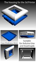
The housing for the 3d Printer
...the housing for the 3d printer 3docean arduino device housing stl the housing consists of two portions:...
3d_export
$5
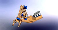
arm 4 axis
...uno -4 servo motor 180° -3 joystick (x,y) for arduino -mdf wood -some wires -cnc laser cut...
3d_export
$5

solar tracker
...machine for the frame . list of material : -arduino uno -2 step motor with driver -4 ldr sensor...
Fan
3d_export
$5
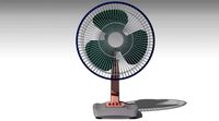
fan
...fan
3dexport
fan 3d model, table fan, fan, electric fan, ventilator
archibase_planet
free

Fan
...fan
archibase planet
fan large fan
fan out n260707 - 3d model for interior 3d visualization.
archibase_planet
free
Fan
...fan
archibase planet
fan ceiling fan ventilator
fan stealth n300615 - 3d model (*.gsm+*.3ds) for interior 3d visualization.
3d_export
$15

fan
...fan
3dexport
is an ancient fan
3ddd
$1
Fan-C-Fan by marco gallegos
...n-c-fan by marco gallegos
3ddd
вентилятор , marco gallegos
fan-c-fan by marco gallegos
3d_export
$10
fan
...fan
3dexport
a detailed fan designed for home or space blowing is now available for only 19.99!
turbosquid
$1
Fan
...fan
turbosquid
free 3d model fan for download as on turbosquid: 3d models for games, architecture, videos. (1427865)
turbosquid
$14
Fan
...fan
turbosquid
royalty free 3d model fan for download as on turbosquid: 3d models for games, architecture, videos. (1415642)
3ddd
$1

Светильник Fan
...светильник fan
3ddd
fan , italamp
светильник fan, производитель italamp
turbosquid
$25
Fan
...fan
turbosquid
royalty free 3d model fan for download as c4d on turbosquid: 3d models for games, architecture, videos. (1483246)
Case
3d_export
$1
case
...case
3dexport
case
archibase_planet
free
Case
...case
archibase planet
showcase show-case glass case
glass-case + cakes - 3d model for interior 3d visualization.
archibase_planet
free
Case
...case
archibase planet
showcase show-case glass case
glass-case for chips - 3d model for interior 3d visualization.
archibase_planet
free
Case
...case
archibase planet
case shelving drawer
case - 3d model for interior 3d visualization.
archibase_planet
free
Case
...case
archibase planet
case rack locker
case - 3d model for interior 3d visualization.
archibase_planet
free
Case
...case
archibase planet
case drawer kitchen furniture
case - 3d model for interior 3d visualization.
archibase_planet
free
Case
...case
archibase planet
case cupboard shelving
glass case - 3d model for interior 3d visualization.
archibase_planet
free
Case
...case
archibase planet
case handbag suitcase
case - 3d model (*.gsm+*.3ds) for interior 3d visualization.
archibase_planet
free
Case
...case
archibase planet
case suitcase
case 5 - 3d model (*.gsm+*.3ds) for interior 3d visualization.
archibase_planet
free
Case
...case
archibase planet
locker case dresser
case - 3d model (*.gsm+*.3ds) for interior 3d visualization.