Thingiverse
BlueRetro_PS1 by mi213
by Thingiverse
Last crawled date: 4 years, 3 months ago
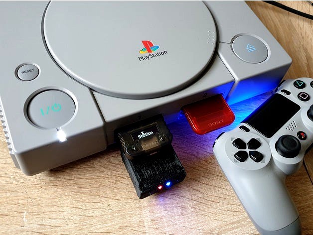
This is a bluetooth receiver for the PS1 / PS2. With the receiver, modern wireless Bluetooth controllers can be used on the PS1 and PS2.
This receiver is based on the BlueRetro project. BlueRetro supports many classic consoles, not just the PS1 / PS2. For more information see: https://github.com/darthcloud/BlueRetro
An ESP32 is required for BlueRetro. I used an ESP32 d1 mini board for the receiver because it is quite small. I also designed a small circuit board that offers space for a voltage converter, makes wiring easier and brings two buttons and two LEDs to the front of the housing.
Together with this 3d printed housing it results in a compact receiver.
The parts needed for this receiver are:
• 3d printed case
• PS1 / 2 controller connector
• ESP32 d1 mini
• BlueRetro_PS1_Shield (with components)
• 4 pieces m2x16 machine screws
• 4 pieces m2 nuts
3d printed case:
This should be easy to print. The lower part has to be printed with support, but this can also be removed without problems.
I printed it in PAL with a resolution of 0.2mm.
PS1 / 2 controller connector:
I made two different versions of the lower part of the case: BlueRetro_PS1_bottom and BlueRetro_PS1_bottom_alt.
The normal version is for the controller plug from an original PS2 controller. Original PS1 controller plugs should also fit.
I made the alternative version for the plug from a cheap controller extension cable from Aliexpress. These are designed a little differently and I had to adapt the housing. The small bars on the housing fit into the recesses on the underside of the controller connector. They should hold the plug and prevent the contact pins from slipping. But since this does not hold so well, I recommend fixing the contact pins with a drop of glue in each of the recesses. I used 2k Epoxy for this.
The controller extension cables I used were these.
The original controller connector has a significantly better quality and is therefore recommended.
ESP32 d1 mini:
With some ESP32 d1 mini boards I had the problem that BlueRetro does not start reliably. The fault was the small 3.3V LOD on the d1 mini board. My shield is designed so that the 8V are converted from the PS1 to 5V and supply the d1 mini via the 5V. The 5V are then converted to 3.3V on the d1 mini board.
To get around the problem, I fitted my shield with a 3.3V LDO and moved the conductor track. So I supply the EPS32 directly with 3.3V. If you have similar problems, this would be a solution. I will adjust the shield again with solder bridges, so that you can choose yourself whether you want to use a 5V or 3.3V LOD.
Update:
The new version 1.2 of the shield now has solder jumpers. A 3.3V LDO can now also be used.
BlueRetro_PS1_Shield:
The shield can be found here: BlueRetro_PS1_Shield_v1.1
Update:
The new version 1.2 of the shield now has two solder jumpers with which the output of the LDO can be set to either 3.3V or 5.0V. So you can choose between a 3.3V and 5.0V LDO.
The new v1.2 can be found here: BlueRetro_PS1_Shield_v1.2
You can order it directly from OSH Park (1.6mm thickness) or download the Gerber file there and order the PCB elsewhere.
The list of SMD components is on the back of the board:
U1: ESP32 d1 mini
U2: SOT223 1117-5.0V (or 3.3V, modifications to the board are necessary!)
C1, C2: 10uF in 1206
C3: 1nF in 0805
R1: 10k in 0805
R2, R3: 1k in 0805 (I used 4.7k so the LEDs aren't too bright)
You also need two 3mm LEDs (red and blue). This should not be too bright and the housing deffus.
And two 2x Tactile Push Button right-angled mounting in the size 4.5mm x 4.5mm. These are a little harder to find than the usual 6x6mm. I found this on aliexpress and took it in 8mm length: right angled 4.5x4.5 Push Button
Flashing the firmware:
All information about flashing the ESP32 d1 mini can be found on the github page.
You need the BlueRetro_psx_ps2_spiffs.bin
This is loaded onto the ESP32 together with bootloader.bin and partition-table.bin using the Flash Download Tool.
Also, you need to install the USB driver for CP2104 USB to UART bridge.