Thingiverse
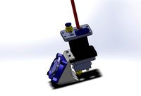
Blood Drive - BLVProjects Ender 3 Conversion Mod - Direct Drive - For Mosquito Hotend w/ BMG-M Extruder by stormbringer91
by Thingiverse
Last crawled date: 3 years, 4 months ago
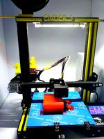
This mod is based on having converted your Ender-3 Pro to the linear rail conversion kit from BLV Projects
As well ownership ofSlice Engineering's Mosquito Hotend and the BMG-M from Bondtech
If you intend on doing this modification to your printer, PLEASE read through or you will damage your printer bed!!! With that at the forefront-
Design purpose:
To reduce imbalanced inertia from stepper motor weight in a direct drive configuration and to maximize printing stability and precision.
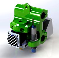
I wanted to be able to attach Bondtech's BMG-M, which was specially purposed to fit to Slice Engineering's Mosquito Hotend. After obtaining both, I could not find a way to mount them.
The vast majority of X-Axis plates will be too tall in height to allow direct mounting of the BMG-M to the Mosquito with the extruder facing front and the stepper motor mounted over the top of the X-Axis rail, as the nozzle won't be able to touch the build plate, since the Mosquito is a very compact hotend. The stock creality X-Axis plate will not work.
This is not an issue for the BLV X-Axis Carriage however!
I didn't attempt to design a duct. So I went looking for the best design that would also be compatible with my design.
Hangtight's ducts proved in my tests to be the best engineered & highest flow. After consulting with him, I have gained his permission to use his duct and include it as part of this design.
Special thanks to Hangtight.
I: Design Challenges & CAUTION:
Small form factor, there is 5mm of clearance between the tip of the Nozzle and the bottom of the BLV X-Axis Carriage with the Mosquito in its lowest mounted position. There's no way around this.
What this means is as the nozzle comes to the bed, the belt clips will hit the bed first.
The stock bed strain will also be in the way as the printhead approaches the back left of the bed, where the cables extend above the flat plane of the bed.
Finally, because of the reduced form factor of the Mosquito, the linear rails need to be lowered down to allow the Z-axis to come down far enough for the nozzle to touch the bed.
Since this needs to happen, the height between the Z-axis Linear Rails and the bed is CRITICAL. If the linear rails are mounted too low, the bed will slam against the sides of the linear rails. If the linear rails are mounted too high, the rail carriage blocks will partially come off the rail channels as the nozzle meets the heated bed platform.
II: Solutions
1) The brass belt clips that are attached to the underside of the BLV X-Axis Carriage are too long and need to be reduced.
Option A - Print my remixed belt clips. You need to be able to remove the existing belt clips, do not clip them off. It can be quite a pain to remove the brass clips, but you can accomplish it using some pliers or needle nose, a small flathead screwdriver and your brain. If you can't manage removing the belt clips you will need to buy another belt that isn't crimped, as you need all of the length from the belt provided in the BLV kit.
Option B - By clipping the brass belt clips down to 3-4mm maximum in height with a side cutter or pliers with a cutting edge. Please don't attempt to cut them down with the blue flush cutters included with the Ender 3, they far too cheap and brittle to cut brass.
2) An alternative bed strain must be printed to prevent the BLV-X Axis carriage belt clips from coming into contact with the stock bed strain and its cables. I've found two on thingiverse that are adequate, both links are provided at the bottom of this page.
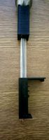
3) The Z-Axis Linear Rails must be lowered down in order for the printer head to reach the print bed. This can be accomplished easily without any disassembly of your printer.
III: Hardware & Installation
Hardware:
(Button head screws are required where stated in order to fit)
Blood Drive to X axis plate:
(3) 3x8mm button head screws
(1) 3x12mm screw(can be longer)
Mosquito Hardware:
(2) 2.5x15mm button head screws
BLtouch Mount Hardware:
(2) 3x10 or 3x12mm button head screws (BLTouch Mount to Blood Drive)
(2) 3x8-10mm button head screws (BLTouch to BLTouch Mount)
(4) 3mm nuts; Two retaining the BLtouch to the mount itself, and two retaining the mount to the Blood Drive.
Hardware for 5015 Fan Duct with Duct Adapter Mount:
(2) 3x20mm screws for 5015 Fan
(2) 3x4mm screws (Duct adapter to Blood Drive)
(2) 3x12mm Screws (Fan Duct to Blood Drive)
(6) M3 Nuts (Two for Fan Duct, Four for Duct Adapter Mount)
Blood Drive Installation:
First off and most importantly, be careful of overtightening and stripping out the holes in the x-axis plate. These are steel screws going into aluminum and it's very easy to do so. Follow basic torquing rules and always tighten your screws in a staggered fashion.
Before installing, Push-fit all of the M3 nuts into place on the Blood Drive.
Insert the 2.5x15mm button head screws into the depressed cavities on the backside of the drive.
Be certain that there isn't any filament ooze/stringing or stuck supports in the way of the M2.5 screws going into the Mosquito. If the screws are not seated properly into the depressed cavities before pressing the drive onto the x-axis plate, your Mosquito will not sit flush against the Blood Drive and/or you will strip the Mosquito's threads.
As this is a depressed fit design, the blood drive should be able to fit flush, directly onto the X-axis plate. If it does not, check to see where you might need to cut away or sand any plastic so that it can slide all the way into place, flush to the plate. If you don't do this, you will be relying on the screws pressure/force to smoosh down any plastic deposits, which the aluminum threads are unlikely to handle. If you have bleeding edges, it will tilt the mosquito so the hotend is not perpendicular to the build plate.
Position the Mosquito with the attached BMG-M into mounting position.
Screw in the 2.5x15mm screws one at a time, starting with the left(facing front) screw first, finger tight, then the right screw.
Then you may place your stepper motor in (wiggle it up and down to fit into the extruder gear) and tighten the stepper motor to the extruder.
AGAIN, you don't need to tighten this stuff very hard. Don't overtighten, or it will bind up the stepper motor gears with the BMG-M gears. You can spin the extruder gear to feel if it is binding.
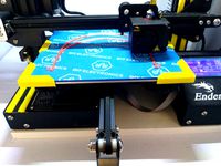
Follow pictures for the rest.
Bed Strain & Z-Linear Rail adjustments:
After you have printed everything you will need and are ready to install the bed strain and blood drive, now is a good time to adjust the Z-rails.
To slide down the linear rails, use the MGN-12 jig alignment tools you should have from installing the rails previously, placing one on the top and bottom.
Center your X-axis carriage in the middle spot on the Z-linear rails where no screws are holding the linear rail to the aluminum extrusions.
Slowly Loosen each screw on opposing sides of the linear rail one at a time(do one rail at a time), being sure to not lose the t-nut inside the aluminum extrusion. When you have all of them loose enough, slide the linear rail so there is roughly 33.5mm of space between the top of the z-linear rails and the bottom of the top aluminum extrusion. Now tighten them back up in the same fashion.
Now when you adjust your bed springs, the bed should be no more than 2mm below the bottom of the z-linear rails.
Depending on your setup, you will have full 250mm of Z-space.
If you have Dual-Z with a single stepper and tensioning pulley or Z-braces, that will reduce the Z-height to about 235-240mm.
Printing:
The tolerances in this design are very tight, so be sure to have calibrated your printer.
As printing this object can be a challenge, I will provide a Cura only 3mf file with support blocks built in for the key areas.
Don't let the supports connect from the extruder mounted side to the Stepper motor mounted side. You will have a very difficult time removing supports if you do.
Minimum of 0.16 Layer Height is recommended. 0.12 for best Fitment
I'd also recommend at least 1.8mm thick walls, and 100% infill will give you the strongest part and yet again, better resistance to heat distortion.
The smaller the nozzle, the better the accuracy, and the better the fitment. I use 0.25 Nozzles for anything I want to print with very high accuracy. You can use up to 0.4mm.
My wire strain needs supports to print the concaved recess for countersunk screws.
The fan duct doesn't need supports.
The fan duct can be printed in PLA Pro/Plus if you like but recognize the ducts will deform if your leave your hotend on and/or parked near the heated bed on without the fan spinning.
With that said, you can actually anneal the ducts themselves naturally by printing with the fan spinning at 50%=>, as the radiant heat from the hotend and bed will reach the ducts and exceed the glass transition point, while the fan will keep the plastic cool enough to not melt and deform. PLA Pro can actually obtain a higher glass transition point of 90C, compared to PETG's 75C. I've had success doing this myself.
The belt clips are very small, might be possible with 0.4mm nozzle, but 0.25 will work better.
Firmware adjustments:
BLTouch Offsets:
X-40.2 ; Y-3.72
Firmware Y-Axis Offset:
Y-15.5 (This may be different depending where your y-end stop and rail is at, so just park the print head at the front of the bed and figure out how much you need to add or subtract to the offset)
Printable Surface Area:
X Axis: 230MM
Y Axis: 235MM
Z Axis(no dual z belt/tensioning kit): 250
Z Axis(w/ dual z belt/tensioning kit): 235-240
This modification is not plug and play!
However, I suspect that if you are interested in doing this mod and have already assembled your BLV conversion, you have the tinkering skills to accomplish this modification as well.
If you have found my work to be helpful in acheiving your goals, please consider throwing me a tip if you are able to. I've spent hundreds of hours on this design, improving it, and providing documentation for installation. You can use the tip designer button or click here. Thanks!
Thanks for checking out my design!
And please post your makes.
Why?: I received the Ender-3 Pro as a Christmas gift last year, having expressed interest in 3D Printing before. I became quite interested quickly. Then became the issue of owning a Mosquito and BMG-M with no way to mount it. I have set out to make this machine my own and to maximize its potential. I've learned a lot! It's been a journey.
Height Reduced 90 Degree bed cable Strain : https://www.thingiverse.com/thing:4104141
Alternative Height reduced extended bed cable strain (pay no mind to "drilling a hole" in the summary): https://www.thingiverse.com/thing:4497591
Bed Cable Clip for 4040 Extrusion: https://www.thingiverse.com/thing:3360288
Motherboard Case by ADKS : https://www.thingiverse.com/thing:4622318
Silicone Sock Mold - https://www.thingiverse.com/thing:3793665
Bonus Points Round:
I also designed a dual-z belt tensioning style mod that's purposed for parts from common dual-z kits available for purchase out there.
It incorporates ProperPrinting's Z-brace mod to work with the kit I already bought. This is probably one of the biggest upgrades you can do to your printer.
You can check it out here : https://www.thingiverse.com/thing:4668292
As well ownership ofSlice Engineering's Mosquito Hotend and the BMG-M from Bondtech
If you intend on doing this modification to your printer, PLEASE read through or you will damage your printer bed!!! With that at the forefront-
Design purpose:
To reduce imbalanced inertia from stepper motor weight in a direct drive configuration and to maximize printing stability and precision.
I wanted to be able to attach Bondtech's BMG-M, which was specially purposed to fit to Slice Engineering's Mosquito Hotend. After obtaining both, I could not find a way to mount them.
The vast majority of X-Axis plates will be too tall in height to allow direct mounting of the BMG-M to the Mosquito with the extruder facing front and the stepper motor mounted over the top of the X-Axis rail, as the nozzle won't be able to touch the build plate, since the Mosquito is a very compact hotend. The stock creality X-Axis plate will not work.
This is not an issue for the BLV X-Axis Carriage however!
I didn't attempt to design a duct. So I went looking for the best design that would also be compatible with my design.
Hangtight's ducts proved in my tests to be the best engineered & highest flow. After consulting with him, I have gained his permission to use his duct and include it as part of this design.
Special thanks to Hangtight.
I: Design Challenges & CAUTION:
Small form factor, there is 5mm of clearance between the tip of the Nozzle and the bottom of the BLV X-Axis Carriage with the Mosquito in its lowest mounted position. There's no way around this.
What this means is as the nozzle comes to the bed, the belt clips will hit the bed first.
The stock bed strain will also be in the way as the printhead approaches the back left of the bed, where the cables extend above the flat plane of the bed.
Finally, because of the reduced form factor of the Mosquito, the linear rails need to be lowered down to allow the Z-axis to come down far enough for the nozzle to touch the bed.
Since this needs to happen, the height between the Z-axis Linear Rails and the bed is CRITICAL. If the linear rails are mounted too low, the bed will slam against the sides of the linear rails. If the linear rails are mounted too high, the rail carriage blocks will partially come off the rail channels as the nozzle meets the heated bed platform.
II: Solutions
1) The brass belt clips that are attached to the underside of the BLV X-Axis Carriage are too long and need to be reduced.
Option A - Print my remixed belt clips. You need to be able to remove the existing belt clips, do not clip them off. It can be quite a pain to remove the brass clips, but you can accomplish it using some pliers or needle nose, a small flathead screwdriver and your brain. If you can't manage removing the belt clips you will need to buy another belt that isn't crimped, as you need all of the length from the belt provided in the BLV kit.
Option B - By clipping the brass belt clips down to 3-4mm maximum in height with a side cutter or pliers with a cutting edge. Please don't attempt to cut them down with the blue flush cutters included with the Ender 3, they far too cheap and brittle to cut brass.
2) An alternative bed strain must be printed to prevent the BLV-X Axis carriage belt clips from coming into contact with the stock bed strain and its cables. I've found two on thingiverse that are adequate, both links are provided at the bottom of this page.
3) The Z-Axis Linear Rails must be lowered down in order for the printer head to reach the print bed. This can be accomplished easily without any disassembly of your printer.
III: Hardware & Installation
Hardware:
(Button head screws are required where stated in order to fit)
Blood Drive to X axis plate:
(3) 3x8mm button head screws
(1) 3x12mm screw(can be longer)
Mosquito Hardware:
(2) 2.5x15mm button head screws
BLtouch Mount Hardware:
(2) 3x10 or 3x12mm button head screws (BLTouch Mount to Blood Drive)
(2) 3x8-10mm button head screws (BLTouch to BLTouch Mount)
(4) 3mm nuts; Two retaining the BLtouch to the mount itself, and two retaining the mount to the Blood Drive.
Hardware for 5015 Fan Duct with Duct Adapter Mount:
(2) 3x20mm screws for 5015 Fan
(2) 3x4mm screws (Duct adapter to Blood Drive)
(2) 3x12mm Screws (Fan Duct to Blood Drive)
(6) M3 Nuts (Two for Fan Duct, Four for Duct Adapter Mount)
Blood Drive Installation:
First off and most importantly, be careful of overtightening and stripping out the holes in the x-axis plate. These are steel screws going into aluminum and it's very easy to do so. Follow basic torquing rules and always tighten your screws in a staggered fashion.
Before installing, Push-fit all of the M3 nuts into place on the Blood Drive.
Insert the 2.5x15mm button head screws into the depressed cavities on the backside of the drive.
Be certain that there isn't any filament ooze/stringing or stuck supports in the way of the M2.5 screws going into the Mosquito. If the screws are not seated properly into the depressed cavities before pressing the drive onto the x-axis plate, your Mosquito will not sit flush against the Blood Drive and/or you will strip the Mosquito's threads.
As this is a depressed fit design, the blood drive should be able to fit flush, directly onto the X-axis plate. If it does not, check to see where you might need to cut away or sand any plastic so that it can slide all the way into place, flush to the plate. If you don't do this, you will be relying on the screws pressure/force to smoosh down any plastic deposits, which the aluminum threads are unlikely to handle. If you have bleeding edges, it will tilt the mosquito so the hotend is not perpendicular to the build plate.
Position the Mosquito with the attached BMG-M into mounting position.
Screw in the 2.5x15mm screws one at a time, starting with the left(facing front) screw first, finger tight, then the right screw.
Then you may place your stepper motor in (wiggle it up and down to fit into the extruder gear) and tighten the stepper motor to the extruder.
AGAIN, you don't need to tighten this stuff very hard. Don't overtighten, or it will bind up the stepper motor gears with the BMG-M gears. You can spin the extruder gear to feel if it is binding.
Follow pictures for the rest.
Bed Strain & Z-Linear Rail adjustments:
After you have printed everything you will need and are ready to install the bed strain and blood drive, now is a good time to adjust the Z-rails.
To slide down the linear rails, use the MGN-12 jig alignment tools you should have from installing the rails previously, placing one on the top and bottom.
Center your X-axis carriage in the middle spot on the Z-linear rails where no screws are holding the linear rail to the aluminum extrusions.
Slowly Loosen each screw on opposing sides of the linear rail one at a time(do one rail at a time), being sure to not lose the t-nut inside the aluminum extrusion. When you have all of them loose enough, slide the linear rail so there is roughly 33.5mm of space between the top of the z-linear rails and the bottom of the top aluminum extrusion. Now tighten them back up in the same fashion.
Now when you adjust your bed springs, the bed should be no more than 2mm below the bottom of the z-linear rails.
Depending on your setup, you will have full 250mm of Z-space.
If you have Dual-Z with a single stepper and tensioning pulley or Z-braces, that will reduce the Z-height to about 235-240mm.
Printing:
The tolerances in this design are very tight, so be sure to have calibrated your printer.
As printing this object can be a challenge, I will provide a Cura only 3mf file with support blocks built in for the key areas.
Don't let the supports connect from the extruder mounted side to the Stepper motor mounted side. You will have a very difficult time removing supports if you do.
Minimum of 0.16 Layer Height is recommended. 0.12 for best Fitment
I'd also recommend at least 1.8mm thick walls, and 100% infill will give you the strongest part and yet again, better resistance to heat distortion.
The smaller the nozzle, the better the accuracy, and the better the fitment. I use 0.25 Nozzles for anything I want to print with very high accuracy. You can use up to 0.4mm.
My wire strain needs supports to print the concaved recess for countersunk screws.
The fan duct doesn't need supports.
The fan duct can be printed in PLA Pro/Plus if you like but recognize the ducts will deform if your leave your hotend on and/or parked near the heated bed on without the fan spinning.
With that said, you can actually anneal the ducts themselves naturally by printing with the fan spinning at 50%=>, as the radiant heat from the hotend and bed will reach the ducts and exceed the glass transition point, while the fan will keep the plastic cool enough to not melt and deform. PLA Pro can actually obtain a higher glass transition point of 90C, compared to PETG's 75C. I've had success doing this myself.
The belt clips are very small, might be possible with 0.4mm nozzle, but 0.25 will work better.
Firmware adjustments:
BLTouch Offsets:
X-40.2 ; Y-3.72
Firmware Y-Axis Offset:
Y-15.5 (This may be different depending where your y-end stop and rail is at, so just park the print head at the front of the bed and figure out how much you need to add or subtract to the offset)
Printable Surface Area:
X Axis: 230MM
Y Axis: 235MM
Z Axis(no dual z belt/tensioning kit): 250
Z Axis(w/ dual z belt/tensioning kit): 235-240
This modification is not plug and play!
However, I suspect that if you are interested in doing this mod and have already assembled your BLV conversion, you have the tinkering skills to accomplish this modification as well.
If you have found my work to be helpful in acheiving your goals, please consider throwing me a tip if you are able to. I've spent hundreds of hours on this design, improving it, and providing documentation for installation. You can use the tip designer button or click here. Thanks!
Thanks for checking out my design!
And please post your makes.
Why?: I received the Ender-3 Pro as a Christmas gift last year, having expressed interest in 3D Printing before. I became quite interested quickly. Then became the issue of owning a Mosquito and BMG-M with no way to mount it. I have set out to make this machine my own and to maximize its potential. I've learned a lot! It's been a journey.
Height Reduced 90 Degree bed cable Strain : https://www.thingiverse.com/thing:4104141
Alternative Height reduced extended bed cable strain (pay no mind to "drilling a hole" in the summary): https://www.thingiverse.com/thing:4497591
Bed Cable Clip for 4040 Extrusion: https://www.thingiverse.com/thing:3360288
Motherboard Case by ADKS : https://www.thingiverse.com/thing:4622318
Silicone Sock Mold - https://www.thingiverse.com/thing:3793665
Bonus Points Round:
I also designed a dual-z belt tensioning style mod that's purposed for parts from common dual-z kits available for purchase out there.
It incorporates ProperPrinting's Z-brace mod to work with the kit I already bought. This is probably one of the biggest upgrades you can do to your printer.
You can check it out here : https://www.thingiverse.com/thing:4668292
Similar models
thingiverse
free

Direct Drive V6 MGN12C Mount by BavarianMaker
...advise you to print it in abs or something similar not petg because it will deform as far as...
thingiverse
free

linear rail direct drive bmg mount for ender 3
...opposite of the x motor to reduce belt tension and allow the adjustment of the belt via separate tensioner
update:
x = 28
y = -19
thingiverse
free

BLV mgn cube - Mosquito + BLtouch
...u use the mellow groove mount adapter.
i have not tested this myself but a friend has and it's working very well, apparently.
thingiverse
free

Z Stepper Hotend Cable Clip for Ender-3 by GRU123
...is moved to the far right to verify that there is no excess stress on your cables after fitting/before starting any large prints.
thingiverse
free

Printable modified BMG dual drive extruder for Mosquito/Crazy hotend by ibruno26
...en/3d-model/tool/barebone-supershort-and-superlight-bmg-for-mosquito-crazy-hotend-with-mgn12h-mount-dual-5015-fanduct-and-bltouch
thingiverse
free
Boreas - Bondtech LGX/ Mosquito mount - MGN rail by tonyl321
... raised and lowered with by adjusting only 1 screw, and the blower fan is a 5015.
the mount bolts directly to mgn12 linear rails.
thingiverse
free

Boreas - Modular Mosquito/E3D Hotend Mount/Tevo Tornado/CR10/Ender 3
...this hotend mount is designed to work with the stock heatsink cooler for both the e3d v6 and mosquito, 30mm and 25mm respectively
thingiverse
free

E3D Hemera Linear Mount, BLTouch
...giverse.com/thing:4034643
i decided to completely remake it with integrated bltouch mount and better clearance for the belt mount
thingiverse
free

Tronxy X5SA PRO Direct Drive BMG-M + Mosquito Hotend Mount
...
note: this version does not have a mount for the x-axis homing switch as i'm currently using sensorless homing with my duet2
thingiverse
free

X axis direct drive mount for MGN12H linear rail by jimmyeao
...:4385375
instead.
note, this removes stability, and i wouldn't recommend this mod unless you are running a dual z axis set up
Stormbringer91
thingiverse
free

ADKS - Ender 3 Motherboard Case - 4010 Fan Spacer by stormbringer91
...stormbringer91
thingiverse
this is a spacer to snap any 4010 fans into place for adark studio's ender 3 motherboard case v3.
thingiverse
free

Ender 3 X-Axis Cable Guide - For Direct Drive by stormbringer91
... loom i use, it's pretty great! it's a split loom so you can access your wires easier, and it stays wrapped up very well.
thingiverse
free

Ender 3 Pro Dual Z (Single Stepper) Belt Tensioning Style with Z Brace Frame Support by stormbringer91
...nt to convert your printer over to linear rails, like i have done, and as you can see in the pictures! just check my profile out.
Mosquito
design_connected
$16

Mosquito
...mosquito
designconnected
rex kralj mosquito computer generated 3d model. designed by kralj, niko.
3d_export
$5

Mosquito
...of some place that is destroyed or abandoned long ago. with such models the application would top the charts and prove its worth.
turbosquid
$100

Mosquito
... available on turbo squid, the world's leading provider of digital 3d models for visualization, films, television, and games.
turbosquid
$69

Mosquito
... available on turbo squid, the world's leading provider of digital 3d models for visualization, films, television, and games.
turbosquid
$22

mosquito
... available on turbo squid, the world's leading provider of digital 3d models for visualization, films, television, and games.
turbosquid
$20

Mosquito
... available on turbo squid, the world's leading provider of digital 3d models for visualization, films, television, and games.
turbosquid
$15

mosquito
... available on turbo squid, the world's leading provider of digital 3d models for visualization, films, television, and games.
turbosquid
$3
Mosquito
... model mosquito for download as 3ds, obj, fbx, blend, and dae on turbosquid: 3d models for games, architecture, videos. (1311331)
3d_export
$25

mosquito
...mosquito
3dexport
simple rendering of the scene file
3d_export
$10
Mosquito 3D Model
...mosquito 3d model
3dexport
mosquito insect bug hexapod flyer
mosquito 3d model def 19400 3dexport
Bmg
turbosquid
$3

.50 BMG
... available on turbo squid, the world's leading provider of digital 3d models for visualization, films, television, and games.
turbosquid
$2

.50 BMG
... available on turbo squid, the world's leading provider of digital 3d models for visualization, films, television, and games.
turbosquid
$25
50 BMG Cartridge
...e 3d model 50 bmg cartridge for download as 3ds, max, and obj on turbosquid: 3d models for games, architecture, videos. (1303035)
turbosquid
$30

Sniper 50 bmg
... available on turbo squid, the world's leading provider of digital 3d models for visualization, films, television, and games.
turbosquid
free

Cal 50 BMG
... available on turbo squid, the world's leading provider of digital 3d models for visualization, films, television, and games.
cg_studio
$25
.50 BMG Cartridge3d model
...odel
cgstudio
.3ds .max .obj .wrl - .50 bmg cartridge 3d model, royalty free license available, instant download after purchase.
3d_export
$5
50 caliber BMG round 3D Model
...d 3d model
3dexport
50cal caliber 50 round bullet bmg cartridge browning rifle
50 caliber bmg round 3d model csw92 27660 3dexport
3d_export
$22
.50 BMG Cartridge 3D Model
...ectile rifle round pistol cartridge m2 hb 127x99mm nato browning barrett m82a1
.50 bmg cartridge 3d model plutonius 8091 3dexport
turbosquid
free
LAR Grizzly .50 BMG Sniper
... available on turbo squid, the world's leading provider of digital 3d models for visualization, films, television, and games.
3d_export
$8
cartrige m50 bmg
...aterials are logically named<br>the main format is in 3ds max 2009.<br>satisfcation garranteed..<br>thank you !
Blood
3d_export
$7

blood vessel or blood capillary
...blood vessel or blood capillary
3dexport
this 3d model shows a blood vessel. it is suitable for education and filming,...
3d_export
$5

Blood cells
...blood cells
3dexport
blood cells 3d model
3d_export
$14

Blood Cells
...poiesis and found in the blood. major types of blood cells include; red blood cells (erythrocytes) white blood cells (leukocytes)
turbosquid
$39
blood
... available on turbo squid, the world's leading provider of digital 3d models for visualization, films, television, and games.
turbosquid
$30

Blood
... available on turbo squid, the world's leading provider of digital 3d models for visualization, films, television, and games.
turbosquid
free

blood
... available on turbo squid, the world's leading provider of digital 3d models for visualization, films, television, and games.
3d_ocean
$3

Blood cells in a vein
...lood blood cell blood cells organic red cell red cells vein
a small section of a vein that contain a number of 16 blood red cells
turbosquid
$3
Monster Blood
...bosquid
royalty free 3d model monster blood for download as on turbosquid: 3d models for games, architecture, videos. (1443631)
turbosquid
$49

Blood Elements
...yalty free 3d model blood elements for download as ma and obj on turbosquid: 3d models for games, architecture, videos. (1264399)
turbosquid
$7

Blood toilet
...oyalty free 3d model blood toilet for download as 3ds and obj on turbosquid: 3d models for games, architecture, videos. (1299123)
Hotend
thingiverse
free
hotend by fablab_lueneburg
...hotend by fablab_lueneburg
thingiverse
hotend model
thingiverse
free
Hotend for Graber
...hotend for graber
thingiverse
hotend complement pastes for graber printerhttps://youtu.be/0koxhnsuhdy
thingiverse
free
Hotend adapter by antaviana
...hotend adapter by antaviana
thingiverse
hotend adapter
thingiverse
free
hotend fan by mming1106
...hotend fan by mming1106
thingiverse
hotend fan
thingiverse
free

Hotend schema by ione
...hotend schema by ione
thingiverse
hotend project schema
thingiverse
free
Fabtotum XY Hotend holder for E3D Hotend
...s with integrated supports.
more for the project you can see here: https://kf-designs.com/2019/09/07/fabtotum-printer-conversion/
thingiverse
free
HotEnd Stand by onepointdiy
...tend, when you make your new hotend or repair your j-head or mg-plus hotend.
the hole of 16mm, please adjust using a reamer, etc.
thingiverse
free

fast magnetic hotend changer for Chimera Hotend by Draman
...chimera hotend !
and new basis (the hole from original is to small)
it is a remix form skimmy's fast magnetic hotend changer
thingiverse
free

Hotend Fan Adapter for MicroSwiss All Metal Hotend by jo_schi_man
...
thingiverse
little change for the hotend fan adapter to hold the microswiss all metal hotend (slightly longer and sharp edges).
thingiverse
free
Merlin Hotend by Alejanson
...merlin hotend by alejanson
thingiverse
this is a 1:1 drawing of the classic merlin hotend.
Conversion
3ddd
$1
Conversation Seat
...шетка
the conversation seat made in englandhttp://www.squintlimited.com/products/the_conversation_seat/gold
+ max 2011
3d_export
$10
Converse 3D Model
...converse 3d model
3dexport
converse shoe pc unix mac
converse 3d model electropainter17075 38067 3dexport
turbosquid
$100

converse-shoe
...quid
royalty free 3d model converse-shoe for download as c4d on turbosquid: 3d models for games, architecture, videos. (1398427)
turbosquid
$10
Conversation Furniture
... available on turbo squid, the world's leading provider of digital 3d models for visualization, films, television, and games.
turbosquid
$7
Converse Allstars
... available on turbo squid, the world's leading provider of digital 3d models for visualization, films, television, and games.
design_connected
$16
Conversation Club Chair
...conversation club chair
designconnected
donghia conversation club chair chairs computer generated 3d model. designed by n/a.
design_connected
$27
Hemicycle Conversation Chair
...rsation chair
designconnected
ligne roset hemicycle conversation chair computer generated 3d model. designed by nigro, philippe.
3d_export
$24

Converse keds 3D Model
...converse keds 3d model
3dexport
converse all star ked shoe clothes sports
converse keds 3d model vermi1ion 26201 3dexport
3ddd
$1
Converse All-Star Shoes
...converse all-star shoes
3ddd
кеды , обувь
converse all-star shoes
design_connected
$18
CONVERSE Jack Purcell Sneakers
...converse jack purcell sneakers
designconnected
converse jack purcell sneakers computer generated 3d model.
Ender
3ddd
$1
Enders / Elegance
...enders / elegance
3ddd
обогреватель
уличный газовый обогреватель enders elegance
высота: 2200 мм
3d_export
free
ender 3 frame cavity covers
... of the creality ender 3 - makes it look a bit more attractive it just slides into the open channels of the aluminium framework
turbosquid
$1
pen support for ender 3
...y free 3d model pen support for ender 3 for download as blend on turbosquid: 3d models for games, architecture, videos. (1611282)
3d_ocean
$9
Ender Dragon Minecraft
...ojang obj poly videogames
ender dragon minecraft created with cinema 4d r15 formats included: max 2013 – fbx 2012 – c4d r15 – obj
3d_export
free
Creality ender enclosure webcam mount
...e creality enclosure. sure is better than a tripod. change it up if it helps. i printed pla with 50% infill on my dd ender 3 pro.
3d_export
free
ender 3 enclosure corners
...er corners and 4 upper corners, using 25mmx25mm angled aluminium pieces that gets covered on inside of the frame with plexiglass
3d_export
free
ender 3 3d print bed clips
...ed + normal aluminium bed frame of the creality ender 3 = 6mm (b) these clips are designed for glass plate + aluminium bed = 4mm
3d_export
$5
GRUMPY CAT
...grumpy cat 3dexport grumpy cat to print in ender ...
3d_export
$5

Logs fire
...with one multi material for corona and vray r ender. albedo, normal, uvmap, roughness format jpg 4096x4096 models:...
3d_export
$42
excavator
...is the original size. 0.12 mm printing surface creality ender5 ...
Mod
design_connected
$13
MOD. 4233 - MOD. 4234 Table Lamp
...mod. 4233 - mod. 4234 table lamp
designconnected
arcahorn mod. 4233 - mod. 4234 table lamp computer generated 3d model.
design_connected
$11
MOD.1095
...mod.1095
designconnected
mod.1095 computer generated 3d model. designed by sarfatti, gino.
3ddd
$1
fireplaces mod Spec
...fireplaces mod spec
3ddd
камин
fireplaces mod spec 180x90x125h
3ddd
free
Flos Mod. 2129
... mod
фабрика: flos
модель: mod. 2129
описание: подвесной светильник, металл, белый, черный.
сайт: www.flos.com
turbosquid
$34
Mod Lamp.c4d
... available on turbo squid, the world's leading provider of digital 3d models for visualization, films, television, and games.
turbosquid
$32
MOD A 001
... available on turbo squid, the world's leading provider of digital 3d models for visualization, films, television, and games.
turbosquid
$29
Maars Mod
... available on turbo squid, the world's leading provider of digital 3d models for visualization, films, television, and games.
turbosquid
$15
Mod 70..
... available on turbo squid, the world's leading provider of digital 3d models for visualization, films, television, and games.
turbosquid
$10
MOD Sofa
... available on turbo squid, the world's leading provider of digital 3d models for visualization, films, television, and games.
turbosquid
$1
Mod-Lite
... available on turbo squid, the world's leading provider of digital 3d models for visualization, films, television, and games.
Direct
design_connected
free
Compas Direction
...compas direction
designconnected
free 3d model of compas direction by vitra designed by prouvé, jean.
design_connected
$18
Direction Pivotant
...direction pivotant
designconnected
vitra direction pivotant computer generated 3d model. designed by prouvé, jean.
turbosquid
$6
not direct the front
...oyalty free 3d model not direct the front for download as max on turbosquid: 3d models for games, architecture, videos. (1213034)
turbosquid
$10

Rails Direct
... available on turbo squid, the world's leading provider of digital 3d models for visualization, films, television, and games.
3d_export
$5
Picto toilet directions
...lude 3d files next to rhino6: x3dv, step, igus, obj and stl. double-sided, flipping changes the gender directions to the toilets.
3ddd
$1
fauteuli direction
...d
chair , vitra , fauteuli
fauteuli vitra chair
design_connected
$18
Fauteuil Direction, 1951
...fauteuil direction, 1951
designconnected
vitra fauteuil direction, 1951 computer generated 3d model. designed by prouvé, jean.
3d_export
$5
Directional tactile 3D Model
...tactile 3d model
3dexport
directional tactile braille tile flooring interior
directional tactile 3d model renob000 71068 3dexport
turbosquid
$26

Radio direction finder A
...ty free 3d model radio direction finder a for download as fbx on turbosquid: 3d models for games, architecture, videos. (1212490)
turbosquid
$7

Wooden direction signage
...ty free 3d model wooden direction signage for download as max on turbosquid: 3d models for games, architecture, videos. (1453747)
Drive
turbosquid
$90
Drive
...turbosquid
royalty free 3d model drive for download as blend on turbosquid: 3d models for games, architecture, videos. (1654393)
3d_export
$10

cycloidal drive
...cycloidal drive
3dexport
cycloidal drive
3d_ocean
$5
Flash Drive
...h drive included : – materials – scene ( lighs / room ) – .c4d + .obj for any questions please feel free to contact me thank you.
3d_ocean
$5
Usb drive
...s shaders and a lighting setup. it also has a small animation of it going in and out. i saved it out as both a .blend file and...
3d_ocean
$5

Pen Drive
...est computer drive game model good low poly new pen pen drive textured unwrapped uv very low poly
a very beautiful low poly model
3d_ocean
$10
External hard drive
... is a detailed model of a trekstor external hard drive. you can easily modify the label on the top. simply edit the text objects.
turbosquid
$60

Star Drive
...squid
royalty free 3d model star drive for download as blend on turbosquid: 3d models for games, architecture, videos. (1254314)
turbosquid
$50
Star Drive
...squid
royalty free 3d model star drive for download as blend on turbosquid: 3d models for games, architecture, videos. (1263524)
turbosquid
$45
Star Drive
...squid
royalty free 3d model star drive for download as blend on turbosquid: 3d models for games, architecture, videos. (1287060)
turbosquid
$40
Star Drive
...squid
royalty free 3d model star drive for download as blend on turbosquid: 3d models for games, architecture, videos. (1261902)
Extruder
3ddd
$1
Extruded Chair
...extruded chair
3ddd
extruded , tom dixon
inspired by tom dixon extruded chair
turbosquid
$15
Extruded Table
... extruded table for download as blend, dae, fbx, obj, and stl on turbosquid: 3d models for games, architecture, videos. (1634137)
turbosquid
$2
3D Printer Extruder
...d
royalty free 3d model 3d printer extruder for download as on turbosquid: 3d models for games, architecture, videos. (1537359)
turbosquid
$1
Zombie extruded text
...oyalty free 3d model zombie extruded text for download as obj on turbosquid: 3d models for games, architecture, videos. (1322198)
turbosquid
$4
Extruder conical screw
...el extruder conical screw for download as sldpr, ige, and stl on turbosquid: 3d models for games, architecture, videos. (1524433)
turbosquid
$50
3d PRINTER - Extruder
... available on turbo squid, the world's leading provider of digital 3d models for visualization, films, television, and games.
turbosquid
$15
Extruded Table 2
...xtruded table 2 for download as blend, dae, fbx, obj, and stl on turbosquid: 3d models for games, architecture, videos. (1621846)
turbosquid
$10
Maya Extrude Tool
... available on turbo squid, the world's leading provider of digital 3d models for visualization, films, television, and games.
3d_export
$5

world earth extrude map
...world earth extrude map
3dexport
3ddd
$1
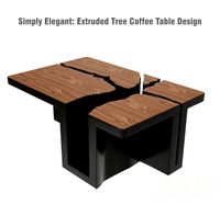
Simply Elegant Extruded Tree Coffee Table Design
...ble by link studios. the silhouette of a tree is visible at one angle, extruded from the surface to create the support structure.
W
3ddd
$1
chair W
...chair w
3ddd
chair w
3ddd
$1

кресло w
...кресло w
3ddd
капитоне
кресло w
3ddd
$1
KUTEK (W) W-ZW-5
...kutek (w) w-zw-5
3ddd
kutek
3d модель люстри (w) w-zw-5 фабрики kutek. в архиве: max2012, obj, fbx, mat.(два варианта металла)
3ddd
$1
KUTEK (W) W-ZW-3
...kutek (w) w-zw-3
3ddd
kutek
3d модель люстри (w) w-zw-3 фабрики kutek. в архиве: max2012, obj, fbx, mat. (два варианта металла)
3ddd
$1
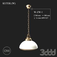
KUTEK (W) W-ZW-1
...kutek (w) w-zw-1
3ddd
kutek
3d модель люстри (w) w-zw-1 фабрики kutek. в архиве: max2012, obj, fbx, mat (два варианта металла).
3ddd
free
aneken W&W
...aneken w&w
3ddd
2 женских манекена, ценники и фолио. материалы и текстуры прилагаются.
design_connected
$9
KTribe W
...ktribe w
designconnected
ktribe w computer generated 3d model. designed by starck, philippe.
design_connected
$16

Troy W
...troy w
designconnected
magis troy w computer generated 3d model. designed by wanders, marcel.
turbosquid
$9
Menu - Benjamin Hubert - W W Carafe
... available on turbo squid, the world's leading provider of digital 3d models for visualization, films, television, and games.
turbosquid
$9

Menu - Benjamin Hubert - W W Carafe
... available on turbo squid, the world's leading provider of digital 3d models for visualization, films, television, and games.
M
turbosquid
$20
Stage M&M
... available on turbo squid, the world's leading provider of digital 3d models for visualization, films, television, and games.
3ddd
$1

bag m&m's
...bag m&m's
3ddd
bag m&m's
bag m&m;'s
3d_export
$35
iskander m
...iskander m
3dexport
iskander m 3d model
design_connected
$7
barstool m
...barstool m
designconnected
barstool m computer generated 3d model.
3ddd
free
CACTUS M
...cactus m
3ddd
cactus , lzf
настольный светильник cactus m
производитель lzf
design_connected
$13
Anfora M
...anfora m
designconnected
lzf anfora m computer generated 3d model. designed by herranz, miguel.
3ddd
$1
зеркало M Gastone
...зеркало m gastone
3ddd
зеркало m gastone
зеркало m gastone
design_connected
$16
Dogon M
...dogon m
designconnected
emmemobili dogon m chairs computer generated 3d model. designed by ferruccio laviani.
design_connected
$9
Sunlight M
...sunlight m
designconnected
bonacina pierantonio sunlight m computer generated 3d model. designed by bizzozzero, franco.
3ddd
$1
Karman / Norma-M
...arman , norma-m
http://www.karmanitalia.it/en/prodotto/norma-m/norma-m-ap640n/
3
turbosquid
$10
Mountain Bike 3 -3 of 3
...model mountain bike 3 (#3 of 3) for download as fbx and blend on turbosquid: 3d models for games, architecture, videos. (1438752)
turbosquid
$6

Rock 3-3
...urbosquid
royalty free 3d model rock 3-3 for download as obj on turbosquid: 3d models for games, architecture, videos. (1628065)
turbosquid
$29
Books 150 pieces 3-3-3
...books 150 pieces 3-3-3 for download as max, obj, fbx, and stl on turbosquid: 3d models for games, architecture, videos. (1384033)
turbosquid
$3

Genesis 3 Clothing 3
... available on turbo squid, the world's leading provider of digital 3d models for visualization, films, television, and games.
3d_export
$5
hinge 3
...hinge 3
3dexport
hinge 3
3ddd
$1
Розетка 3
...розетка 3
3ddd
розетка
розетка 3
turbosquid
$50
is-3
... available on turbo squid, the world's leading provider of digital 3d models for visualization, films, television, and games.
turbosquid
$10
Mountain Bike 3 -2 of 3
...model mountain bike 3 (#2 of 3) for download as fbx and blend on turbosquid: 3d models for games, architecture, videos. (1438750)
turbosquid
$10
Mountain Bike 1 -3 of 3
...model mountain bike 1 (#3 of 3) for download as fbx and blend on turbosquid: 3d models for games, architecture, videos. (1438743)
3d_export
$5

3 CATS
...3 cats
3dexport
3 cats pen holder