Thingiverse
Big DIY 3D printer 2 by JobSmolders
by Thingiverse
Last crawled date: 3 years ago
Big DIY 3D printer 2
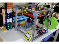
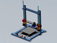
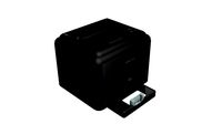
This 3D printer is a modification of the Big DIY 3D Printer. I decided to make a new thing of it because I changed so much.
The idea of this printer is to make it with materials you already have to keep it cheap.
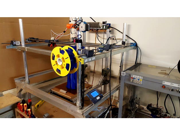
Basically a 3D printer is an X, Y and Z axis. This model is an X and Y axis that can be brought up as high as you want, and so making it bigger on the Z axis. In my example I made an Z axis from extruded aluminum lengths (30x33mm) and 608Z bearings I had. I included the files for the Z axis also if you want to make the Z axis this way. The X and Y axis can also be made as long as you want. The length is determent by the length of 10mm rods you use. My rods are 1000mm long. In my case that means the maximum length of X and Y are 835mm by 710mm. My Z hight is 680mm at the moment because the aluminum lengths I have are not any longer. But If they where I would make the Z axis 2 meter :-) .
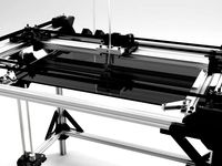
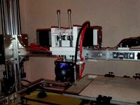
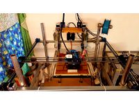
But the reason for the upgrade is that a big printer has it's issues. Printing big objects means that it will take a lot of time. So you want to speed it up. But then vibrations and sound will be much stronger. Also the longer your rods are the more vibrations you will get. (I'm thinking of using these carbon fiber ones because they are much stiffer, they say). So to make these effects less, I made this much lighter X axis and X car setup. Now the X car can move much faster with less vibrations. With PLA and PET-G this setup works much better than the old one. I removed the geared extruder from the X car to the side using a DIY “Bowden setup”.
On the X car I only have a hot end and fans now. The fan brackets in red ABS are not of my own design but from RoPa here on Thingiverse : http://www.thingiverse.com/thing:1264477. I like this design and it fit's this minimalistic setup :-) .
The controller and firmware are still the same as with Big DIY 3D printer. If you are interested in that please visit :https://www.thingiverse.com/thing:2603668
To reduce vibrations and noise I experimented with a DIY vibration “dampeners” made out of silicon.
I cut these silicon “dampeners” out of a baking mat bought in a cheap Chinese products store.
The Yellow plastic peace is my template for cutting the once for the motors.
I know there are still direct contact areas from the motors to the rest of the printer frame. I didn’t fully isolate the mounting bolts.
But for now the results are good. There is much less noise and vibrations and the print is good. :-)
Update Jan-06-2018 :
The point where the timing belt was connected broke :-(
So I made this alternative repair part :-)
Also the original part is slightly modified. But If you got your one broken also this repair part may come in handy. I called the part “timing belt mounting point broken repair part1A & B.STL. Also the additional picture may explain more :-).
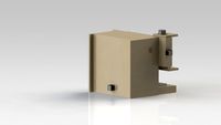
Feb-06-2018 :Geared Extruder Update
included file: geard extruder STLs.ZIP
I made a new Extruder for this super DIY “bowden setup” :-).
My aim was to make it simple, strong and that the filament could be pressed super hard against the driver gear. Filament can be guided with a adjustable guide. For now I kept the gland nut, but included parts that can be adjusted for regular Teflon tube holders. On the printer on the pictures the gland nut works really well. This extruder en tube setup has made the print test of 20 hours. But on another printer of mine the gland nut works not so good. It's because that one prints with much higher speeds (60mm/s and higher) and than the gland nut does not hold so good anymore. I found that it does help to put Katon tape one the tube :-) I am still experimenting with other tube holder methods :-)
The little filament driver (11mm diameter) is mounted on an M8x50mm bolt I had lying around. On the lathe I turned the end of this M8 bolt down to 5mm so the driver can be mounted on it. See pictures
Teflon tube holder upgrade FEB-20-2018 update
This upgrade is about replacing the gland nut for tube holder clips. See pictures
Experimenting with these clips I came to the understanding that the diameter of the hole where the clip is placed in is very important. Because not all Teflon tubes are the same size the diameter of this hole can be different. The Teflon tubing I have is between 3 – 4 mm. So for me it works best that to bore out the hole with a 6.5mm. But I recommend to begin with 6mm. If that is too tight, bore 6.5mm and so on.
If you have any questions feel free to ask :-)
Parts list for the X Y & Hot End setup:
6X F625ZZ bearing wheel
6X 623Z bearing
4X LM10UU/SP linear bearing
4X SCS10UU linear bearing
4X xxx length x10mm gliding rod
3X Nema 17 Stepper Motor
3X Timing belt pulley and matching timing belts
2X End Switch
Bowden Extruder Setup
Hot End & wires
19X M5x30mm bolt
3X M5 nut
3X M4x40mm bolt
4X M4x20mm bolt
4X M4x10mm bolt
15X M4 nut
30X M3x10mm bolt
4X M3x20mm bolt
2X M3x40mm bolt
27X M3 nut
For the Z axis setup you need:
16X 608ZZ bearing
1X end switch
16X M8 bolt or threaded rod 8mm and nuts
2X spindle 8mm and spindle nut or M8 threaded rod and nut
2X stepper Nema 17
2X motor to spindle connector 5mm to 8mm
6X M4x40mm bolt
6X M4 nut
8X M3x10mm bolt
8x M3x20mm bolt and nuts are optional if you use the M8 converter part.
1X heat bed and power supply that can deliver the current (I have a 12V /360W)
For the Controller You need:
1X Arduino Mega
1X Ramps 1.4 board and Full graphic smart controller
6X stepper driver A4988 or DRV8825 (you will have to hack your ramps to install all of them :-) )
1X 12V/240W power supply (I have a 360W)
1X opto coupler and FET for switching the heat bed (you can buy them as a board)
1X fan to cool the drivers (I have an 80 x 80 mm)
the blue and green parts are printed in PET-G resolution 0,2mm
This 3D printer is a modification of the Big DIY 3D Printer. I decided to make a new thing of it because I changed so much.
The idea of this printer is to make it with materials you already have to keep it cheap.
Basically a 3D printer is an X, Y and Z axis. This model is an X and Y axis that can be brought up as high as you want, and so making it bigger on the Z axis. In my example I made an Z axis from extruded aluminum lengths (30x33mm) and 608Z bearings I had. I included the files for the Z axis also if you want to make the Z axis this way. The X and Y axis can also be made as long as you want. The length is determent by the length of 10mm rods you use. My rods are 1000mm long. In my case that means the maximum length of X and Y are 835mm by 710mm. My Z hight is 680mm at the moment because the aluminum lengths I have are not any longer. But If they where I would make the Z axis 2 meter :-) .
But the reason for the upgrade is that a big printer has it's issues. Printing big objects means that it will take a lot of time. So you want to speed it up. But then vibrations and sound will be much stronger. Also the longer your rods are the more vibrations you will get. (I'm thinking of using these carbon fiber ones because they are much stiffer, they say). So to make these effects less, I made this much lighter X axis and X car setup. Now the X car can move much faster with less vibrations. With PLA and PET-G this setup works much better than the old one. I removed the geared extruder from the X car to the side using a DIY “Bowden setup”.
On the X car I only have a hot end and fans now. The fan brackets in red ABS are not of my own design but from RoPa here on Thingiverse : http://www.thingiverse.com/thing:1264477. I like this design and it fit's this minimalistic setup :-) .
The controller and firmware are still the same as with Big DIY 3D printer. If you are interested in that please visit :https://www.thingiverse.com/thing:2603668
To reduce vibrations and noise I experimented with a DIY vibration “dampeners” made out of silicon.
I cut these silicon “dampeners” out of a baking mat bought in a cheap Chinese products store.
The Yellow plastic peace is my template for cutting the once for the motors.
I know there are still direct contact areas from the motors to the rest of the printer frame. I didn’t fully isolate the mounting bolts.
But for now the results are good. There is much less noise and vibrations and the print is good. :-)
Update Jan-06-2018 :
The point where the timing belt was connected broke :-(
So I made this alternative repair part :-)
Also the original part is slightly modified. But If you got your one broken also this repair part may come in handy. I called the part “timing belt mounting point broken repair part1A & B.STL. Also the additional picture may explain more :-).
Feb-06-2018 :Geared Extruder Update
included file: geard extruder STLs.ZIP
I made a new Extruder for this super DIY “bowden setup” :-).
My aim was to make it simple, strong and that the filament could be pressed super hard against the driver gear. Filament can be guided with a adjustable guide. For now I kept the gland nut, but included parts that can be adjusted for regular Teflon tube holders. On the printer on the pictures the gland nut works really well. This extruder en tube setup has made the print test of 20 hours. But on another printer of mine the gland nut works not so good. It's because that one prints with much higher speeds (60mm/s and higher) and than the gland nut does not hold so good anymore. I found that it does help to put Katon tape one the tube :-) I am still experimenting with other tube holder methods :-)
The little filament driver (11mm diameter) is mounted on an M8x50mm bolt I had lying around. On the lathe I turned the end of this M8 bolt down to 5mm so the driver can be mounted on it. See pictures
Teflon tube holder upgrade FEB-20-2018 update
This upgrade is about replacing the gland nut for tube holder clips. See pictures
Experimenting with these clips I came to the understanding that the diameter of the hole where the clip is placed in is very important. Because not all Teflon tubes are the same size the diameter of this hole can be different. The Teflon tubing I have is between 3 – 4 mm. So for me it works best that to bore out the hole with a 6.5mm. But I recommend to begin with 6mm. If that is too tight, bore 6.5mm and so on.
If you have any questions feel free to ask :-)
Parts list for the X Y & Hot End setup:
6X F625ZZ bearing wheel
6X 623Z bearing
4X LM10UU/SP linear bearing
4X SCS10UU linear bearing
4X xxx length x10mm gliding rod
3X Nema 17 Stepper Motor
3X Timing belt pulley and matching timing belts
2X End Switch
Bowden Extruder Setup
Hot End & wires
19X M5x30mm bolt
3X M5 nut
3X M4x40mm bolt
4X M4x20mm bolt
4X M4x10mm bolt
15X M4 nut
30X M3x10mm bolt
4X M3x20mm bolt
2X M3x40mm bolt
27X M3 nut
For the Z axis setup you need:
16X 608ZZ bearing
1X end switch
16X M8 bolt or threaded rod 8mm and nuts
2X spindle 8mm and spindle nut or M8 threaded rod and nut
2X stepper Nema 17
2X motor to spindle connector 5mm to 8mm
6X M4x40mm bolt
6X M4 nut
8X M3x10mm bolt
8x M3x20mm bolt and nuts are optional if you use the M8 converter part.
1X heat bed and power supply that can deliver the current (I have a 12V /360W)
For the Controller You need:
1X Arduino Mega
1X Ramps 1.4 board and Full graphic smart controller
6X stepper driver A4988 or DRV8825 (you will have to hack your ramps to install all of them :-) )
1X 12V/240W power supply (I have a 360W)
1X opto coupler and FET for switching the heat bed (you can buy them as a board)
1X fan to cool the drivers (I have an 80 x 80 mm)
the blue and green parts are printed in PET-G resolution 0,2mm
Similar models
thingiverse
free
Portable 3D Printer by JobSmolders
...amp; screws for the housing are not included in this list. if you want to know feel free to ask :-)
the hinges use m4 x60mm bolts
thingiverse
free
VEE CORE XY by maxdesign1990
...h - 300mm 2x
linear shaft
12mm dia shaft length - 400mm 2x
linear bearing
linear bearing 12mm lm12uu 4x
cults
free

Geared Extruder
... . for 2,85mm & 3mm filament the holes need to bored out to the correct size.
if you have any questions feel free to ask
thingiverse
free
Dual Extruder by Psycho1981
...ng:
4x allen screw m5
4x square nut m5
4x washer m5
electronic:
-ramps 1.4 board
-atx power supply
-firmware "marlin"
thingiverse
free
Remix of Ulticube by shivackt
... m2 8mm (for the hotend)
2x m3 22mm (for the part cooler)
https://youtu.be/60zclhke-rehttps://www.youtube.com/watch?v=izpw6stqzsy
cults
free

BIG DIY 3D Printer
...11mm driver 1x m8 x 50mm bolt or something similar 1x hot-end 2x snail house fan 1x spring (optional,...
thingiverse
free

Linear carriage nema 17 by nikki81
...8mm washers
6x 8mm nuts
1x 608zz bearing
4x lm8uu bearings
1x kw11-3z microswitch
8x 100mm cable ties
4x m3 5mm bolts
4x m3 nuts
thingiverse
free

Neck mechanism for animatronics and puppets by Hendrikx
...rc, https://youtu.be/1nalpkerztm list of parts: 3x servo mg995 or similar 4x ball joint 3mm x 3mm (both sides of...
thingiverse
free

Ekobots - Box-H 3D Printer. by jsirgado
...gs like this.
buy my designs at pinshape:http://pinshape.com/users/27920-jsirgado
the openscad file is there, you can change all.
thingiverse
free
BIG DIY 3D Printer by JobSmolders
...11mm driver 1x m8 x 50mm bolt or something similar 1x hot-end 2x snail house fan 1x spring (optional,...
Jobsmolders
thingiverse
free
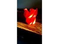
Swirl lamp by JobSmolders
...swirl lamp by jobsmolders
thingiverse
another lampshade :-)
thingiverse
free
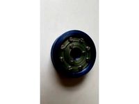
Bearing by JobSmolders
...bearing by jobsmolders
thingiverse
bearing printed in pet-g
needed also : 8x m4x20mm & 3x m3x20mm
thingiverse
free

Pot Head by JobSmolders
...pot head by jobsmolders
thingiverse
the photos speak for them selves :-)
printed in purple abs, res 0.2mm
thingiverse
free

MOCKUP SG90 Servo by JobSmolders
...mockup sg90 servo by jobsmolders
thingiverse
for designers. 123d file included
thingiverse
free
Logo Lamp by JobSmolders
...logo lamp by jobsmolders
thingiverse
printed using “spiralize outer contour mode” in orange translucent pet-g :-)
thingiverse
free

Nr. 9 by JobSmolders
...lders
thingiverse
this is just a little experiment with the “spiralize contour mode” in cura
printed in pet-g transparent smokey
thingiverse
free
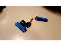
Lighter Holder Round by JobSmolders
...lighter holder round by jobsmolders
thingiverse
a way to connect a lighter to a key chain or hook
thingiverse
free
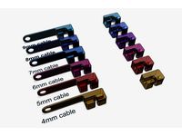
Cable Holder by JobSmolders
...newer and improved version on my own website, go to https://www.designuitinspiratie.nl/3d-printer/kabel-houder/
cable holders :-)
thingiverse
free
Mockup stepper 28BYJ-48 by JobSmolders
...mockup stepper 28byj-48 by jobsmolders
thingiverse
for designers. 123d file included :-)
thingiverse
free
MOCKUP Snail house fan by JobSmolders
...mockup snail house fan by jobsmolders
thingiverse
for designers + 123 3d autodesk file
Diy
3d_export
free
DIY 3D Printer
...diy 3d printer
3dexport
diy 3d printer model
turbosquid
$10

Diy tiered
...l diy tiered for download as max, max, max, max, fbx, and obj on turbosquid: 3d models for games, architecture, videos. (1603709)
turbosquid
$3

Diy Desk to Bench
...odel diy desk to bench for download as 3ds, max, obj, and fbx on turbosquid: 3d models for games, architecture, videos. (1506589)
turbosquid
$2

DIY Moon Light
...model diy moon light for download as obj, fbx, blend, and dae on turbosquid: 3d models for games, architecture, videos. (1501170)
3d_export
$8
DIY CNC Router 3D Model
...diy cnc router 3d model
3dexport
cnc; router; diy; homemade
diy cnc router 3d model maikeru86 58463 3dexport
turbosquid
$5

Diy Kitchen Cabinets
...itchen cabinets for download as 3ds, obj, fbx, blend, and dae on turbosquid: 3d models for games, architecture, videos. (1197373)
3d_export
free

Download free Diying Plant 3D Model
...download free diying plant 3d model
3dexport
diying plant blender
diying plant 3d model visitorsama 98607 3dexport
3ddd
$1
DIY coffee table + decor
... рамка для фото
кофейный столик diy 400х350х600(h) мм. моделился по фото. внимание: материалы - corona.
turbosquid
$3

Diy Wire Lamp Shade
...free 3d model diy wire lamp shade for download as 3ds and fbx on turbosquid: 3d models for games, architecture, videos. (1347605)
cg_studio
$12
DIY MONGOLIAN LAMB STOOLS3d model
... hair soft pile white
.max - diy mongolian lamb stools 3d model, royalty free license available, instant download after purchase.
Big
3ddd
$1

Big Ben
...big ben
3ddd
big ben , часы
часы moooi - big ben
by marcel wanders
3d_export
$5

Sexy big
...sexy big
3dexport
sexy big
3d_export
$5
big sword
...big sword
3dexport
it is a big sword, with a designe
turbosquid
$5
Big
... available on turbo squid, the world's leading provider of digital 3d models for visualization, films, television, and games.
turbosquid
$1
big
... available on turbo squid, the world's leading provider of digital 3d models for visualization, films, television, and games.
3d_export
$5
big monster
...big monster
3dexport
big monster 3d model printing
3ddd
$1
Kioto BIG
...kioto big
3ddd
itre , kioto
kioto big . itre
3d_ocean
$25

Big Bag
...the files are designed with clean topology, so are easy to edit & customize. there are 4 versions of files that are provid...
3ddd
$1
BIG BOB
...
version: 2014
preview: no
units: millimeters
polys: 391984
model parts: 20
render: v-ray
formats: 3ds max 2014, obj
design_connected
$13
Big Table
...big table
designconnected
bonaldo big table computer generated 3d model. designed by gilles, alain.
Printer
archibase_planet
free
Printer
...inter
archibase planet
printer laser printer pc equipment
printer n120614 - 3d model (*.gsm+*.3ds) for interior 3d visualization.
archibase_planet
free
Printer
...rchibase planet
laser printer office equipment computer equipment
printer - 3d model (*.gsm+*.3ds) for interior 3d visualization.
turbosquid
$100
Printer
...er
turbosquid
royalty free 3d model printer for download as on turbosquid: 3d models for games, architecture, videos. (1487819)
turbosquid
$3
Printer
...turbosquid
royalty free 3d model printer for download as max on turbosquid: 3d models for games, architecture, videos. (1670230)
turbosquid
$1
printer
...turbosquid
royalty free 3d model printer for download as max on turbosquid: 3d models for games, architecture, videos. (1595546)
turbosquid
$1
printer
...turbosquid
royalty free 3d model printer for download as max on turbosquid: 3d models for games, architecture, videos. (1595105)
turbosquid
$10
Printer
...id
royalty free 3d model printer for download as max and 3dm on turbosquid: 3d models for games, architecture, videos. (1607146)
turbosquid
$7
Printer
...royalty free 3d model printer for download as ma, ma, and obj on turbosquid: 3d models for games, architecture, videos. (1644580)
turbosquid
$30
Printer
... available on turbo squid, the world's leading provider of digital 3d models for visualization, films, television, and games.
turbosquid
$20
Printer
... available on turbo squid, the world's leading provider of digital 3d models for visualization, films, television, and games.
2
design_connected
$11
No 2
...no 2
designconnected
sibast no 2 computer generated 3d model. designed by sibast, helge.
turbosquid
$6
Cliff Rock 2-2
...uid
royalty free 3d model cliff rock 2-2 for download as obj on turbosquid: 3d models for games, architecture, videos. (1619161)
turbosquid
$29

Book variation 2 2
...3d model book variation 2 2 for download as max, obj, and fbx on turbosquid: 3d models for games, architecture, videos. (1366868)
turbosquid
$22
Classic baluster (2) (2)
...assic baluster (2) (2) for download as max, obj, fbx, and stl on turbosquid: 3d models for games, architecture, videos. (1483789)
turbosquid
$99

Smilodon 2 Pose 2
... available on turbo squid, the world's leading provider of digital 3d models for visualization, films, television, and games.
turbosquid
$20
Barrel Barricade 2-2
... available on turbo squid, the world's leading provider of digital 3d models for visualization, films, television, and games.
turbosquid
$6
Wall Trophy (2) (2)
... available on turbo squid, the world's leading provider of digital 3d models for visualization, films, television, and games.
turbosquid
free
Tire label 2 of 2
... available on turbo squid, the world's leading provider of digital 3d models for visualization, films, television, and games.
3ddd
$1
Кровать, 2 тумбочки, 2 светильника
...кровать, 2 тумбочки, 2 светильника
3ddd
кровать, 2 тумбочки, 2 светильника
нормальное качество
формат 3ds max
без текстур
3ddd
free

Кровать, 2 тумбочки, 2 светильника
...кровать, 2 тумбочки, 2 светильника
3ddd
кровать, 2 тумбочки, 2 светильника
нормальное качество
формат 3ds max
без текстур