Thingiverse
Belt Tension Adjust Truck for SeeMeCNC Ball Joint System and 1"x1" Extrusion by slonold
by Thingiverse
Last crawled date: 3 years ago
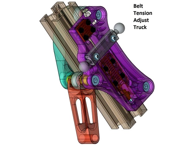
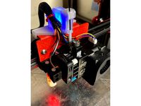
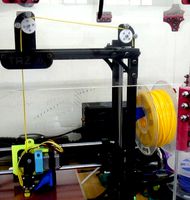
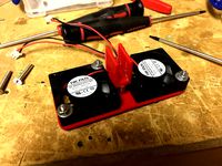
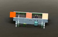
This carriage was inspired by Trick Laser's Trick Truck and a desire to have an easy, reliable and repeatable method of adjusting belt tension. While it is far from trick, the Belt Tension Adjust Truck is tight (much tighter than the molded carriages), fairly light at about 90g including the back shell, utilizes twin eccentric bushings (printable) to precisely set carriage clamping force and incorporates an easy to use belt tension mechanism.
Note that this truck requires OpenBuilds style Mini V Wheels (with extra Precision Shims) and is for use with 1" x 1" slotted extrusion.
Also note that as well as eating up some of your time, these trucks will eat about 25mm or so of Z height.
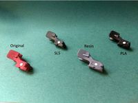
If you go to the trouble of making these trucks, the aluminum Machined Ball Joint "Barbells" from SeeMeCNC are strongly recommend as flex in the plastic ones appears to be the next largest source of motion in the system after slop in the spring loaded molded carriages. In addition, the aluminum barbells are quite true whereas this is not necessarily the case for the plastic ones which can create lack of parallelism and effector tilt problems as well as wide variation in end stop offsets if you use multiple hot ends.
Carbon Arms from Trick Laser are highly recommended.
Parts to Purchase (Note: if you are bereft of bolts see also tool section before ordering)
Running Gear
Mini (15.23mm/0.600" OD) V Wheels Qty 9
Available from MakerParts, OpenBuilds and of course a variety of suppliers on AliExpress including Fussnor
Precision Shims (5mm ID x 8mm OD x 1mm Height) - TOTAL required QTY 27Each Wheel Requires 3!! Carefully check how many shims are included with the wheels from your supplier to determine how many additional shims are required.
i.e. Fussnor, MakerParts, OpenBuilds
5mm x 40mm Socket Head Cap Screw Qty 9Note: Recommend cutting a 50mm bolt down to 40mm in order to get a longer unthreaded shank for a more plastic friendly bearing surface..
5mm Lock Nut Qty 9
Ball Joint Attachment
3mm x 18 or 20mm Button or Socket Head Cap Screw Qty 6(for aluminum barbell)or
3mm x 16 or 18mm Button or Socket Head Cap Screw Qty 6(for plastic barbell).
3mm Lock Nut Qty 6
3mm Washer Qty 6
End Stop Adjustment
3mm x 16 to 20mm Flat Head Screw Qty 3(hex drive recommended)
3mm x 2.5mm Thick Plain Nut Qty 6
Belt Clamps
2.5mm x 10mm Nylon Pan Head Screw Qty 12
2.5mm x 8mm Nylon Pan Head Screw Qty 12
2.5mm Nylon Plain Nuts Qty 24(metal screws +/- lock nuts may be substituted but the screws need to be trimmed by ~ 1mm).
Tension Adjuster
2.5mm x 16mm Socket Head Cap Screw Qty 3
2.5mm Lock Nut Qty 3
2.5mm "DIN125" (5mm OD) Nylon Washer/Spacer Qty 3
Optional End Stop Switch Mounting Hardware Upgrade for Max V2
M2.5 x 18 or 20mm Socket Head Caps Screw Qty 6
M2.5 Lock Nut Qty 6
M2.5 Washer Qty12
Printed Parts Note that dimensional accuracy is important. See instructions for specifics
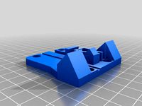
Body - Qty 3Recommend material with a higher flexural modulus such as PLA (i.e.PETG not recommended). Support required. Brim recommended as the wheel bosses are the only bed contact points. Strong cooling recommended to avoid curling as the wheel boss features gradually taper into the body. If possible, (i.e. Slic3r) slow speed considerably for the final layers associated with the barbell mount boss layers to minimize ovality. Overall it is probably better to print at a lower speed. Extrusion Width 0.3 to 0.4mm recommended. Shell Thickness should be about 0.9 to 1mm. Infill 15% Honeycomb. Layer Height 0.2mm or less.
Back_Shell - Qty 3As above, except Infill 10%
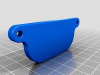
Adjuster_Clamp - Qty 3Recommend PETG for layer adhesion and toughness. Support Required. Extrusion Width 0.3 to 0.4mm recommended. Shell Thickness should be about 0.9 to 1mm. Infill 20% Honeycomb. Layer Height 0.1mm or less.
Fixed_Clamp - Qty 3As above, except support not required.
Eccentric - Qty 6Recommend ABS for natural lubricity and ease of "machining" to size. Extrusion Width 0.3 to 0.4mm recommended. Shell Thickness should be about 0.9 to 1mm. Infill 50% Honeycomb. Layer Height 0.2mm.TEST PRINTING TO MATCH SIZE TO YOUR 5/16 OR 8MM "BORING TOOL" IS STRONGLY RECOMMENDED. See Prepare Eccentric section of Instructions.
Wrench - Qty 1.Any rigid material. Extrusion Width 0.3 to 0.4mm recommended. Shell Thickness should be about 0.9 to 1mm. Infill 20% Honeycomb. Layer Height 0.2mm.
Recommended ToolsDrill Bits
2.5mm
3mm
1/4" or 6.5mm
Reamers (Note: could substitute end mills, drill bits, bits of emery tape wrapped around a shaft etc.)
5mm
5/16" or 8mm
Optional tools for optimizing aluminum barbell sockets
1/4" 4 Flute End Mill
Counter Sink suitable for 1/4" hole.
Ablating Devices
Riffler or similar small file set
1" bastard, aluminum or similar coarse flat file
Emery Tape 200 - 300 grit
Knifes
Reasonably stout and sharp hobby knife or similar
Hex Drivers
2mm
4mm
Sockets and Wrenches
5mm Wrench or Socket (if upgrading end stop switch hardware)
5.5mm Open Ended Wrench
8mm Nut Driver or Thin Walled Socket
Screw Drivers
Small Phillips (cross head)
Small (3 to 4mm width) Flat
Pliers
Medium Slip Joint
Small Needle Nose
Measuring Instruments
Caliper
A method of measuring belt deflection force to 1 - 2 kgfi.e. Hanging,Fish,Luggage Scale
Power Tools
Variable Speed Drill
Fixtures and other Handy Items
2.5mm x 20mm or so fully threaded Socket Head Cap Screw
3mm x 25mm or so fully threaded Socket Head Cap Screw
5mm x 20mm or so fully threaded Socket Head Cap Screw
5mm Lock Nut to be sacrificed as a poor persons lathe fixture
4 or 5mm width x 200mm or so length plastic cable tie
1-2" 6mm GT2 Belt Scrap
Firmware (SeeMeCNC Repetier)
The inner face (mounting surface for the Ball Joint barbell) distance from the Delta Radius (i.e. 200mm for a MaxV2) matches that of the molded carriage. Consequently, the Horizontal Carriage Offset distance does not need to be changed if you already have molded carriages (i.e. 26.5mm for a MaxV2). However the aluminum Machined Ball Joint Carriages have 1mm more of horizontal offset than the plastic barbells so if you are upgrading to the aluminum ones you need to add this distance (i.e. 27.5mm Horizontal Carriage Offset for a MaxV2).
Instructions
Dimension Check
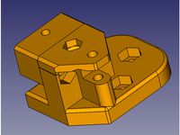
See below for major dimensions, the width (37.5mm) across the two parallel sides at the level of the barbell mount posts is critical for proper functioning of the eccentric wheel adjustment. Best to be within +/- 0.2mm. If the mount posts print a little oval, the major axis should ideally be at least 6.35mm.
Prepare Barbells
Placing a chamfer on the sockets (A) will provide a little relief for the mounting posts where they rise from the body. Size sockets to 1/4" (C) to facilitate fitment.
Clear the Extrusion Tracks on Body and Back Shell
Remove support, then clean up any debris with a course file. Start with the bodies. Remove enough material to achieve a thickness of 10.5mm at the top of the body and 9.5mm at the bottom. Use your eyeball calipers to achieve a similar level of finish on the Back Shells.
Size Barbell Mounting Posts
Probably a good idea to get the posts covered up before they suffer any insults. Measure the posts carefully, the model is sized slightly large to ensure enough material for a good fit. Use a folded over strip of emery tape to work diameter down towards 6.35mm. Work both posts evenly to maintain centre distance and horizontal alignment. This is important to achieve a light press fit and avoid dread effector tilt. Be sure to keep an even dimension along the length of the post and remove (just) any protrusions from the surface were the barbell will seat against the body. As you approach dimension, check the fit regularly as described below in order to avoid the lament "i sanded it twice and it is still loose..."
Place Barbells
Test fit the posts one at a time, the goal is a light press fit. The barbell should slide down to within 2 or 3mm of the body with minimal effort. DO NOT FORCE (A). The reward for a partially jammed on barbell will likely be broken posts and a 4 hour reprint penalty (one might be able to drill and tap a 3mm thread and then place a bolt from the the backside through the length of the post to save the day). Once both posts are sized, apply a little lubricant (B) and test fit (C). There should be just a little resistance with 2 - 3mm to go (D), if this is the case, press the barbell with conviction to seat it fully and test for firmness (E).
Size Post Holes and Prepare Nut Sockets
Start with the 2mm drill and work up to 3mm (A). Be sure you are drilling true and are centred on the backside (B). Chamfer (C) and remove any support debris from the socket (D).
Place Barbell Nuts and Bolts
Prepare a longer M3 bolt, washer and M3 Lock Nut as shown (B), a little lubricant may be useful. Pull the nut into the socket taking care to achieve good alignment. Press the nut well into the socket (C). Install an 18mm (aluminum barbell) and seat nut firmly (D). Ensure bolt does not protrude about surface of extrusion track.
Install End Stop Adjusting Screw
While the 3mm drill bit is still in the drill motor, size the end stop screw hole (~20mm deep) to 3mm (A). Clean any debris from the captive nut slot (5.5mm x 2.5mm) (B). Position a 3mm plain nut (C) and carefully seat with pliers. Take care to avoid rotation of the nut. Otherwise you will be doing surgery on the fixed belt clamp. Run a plain nut up close to the head of the flat head 3mm screw and install.
Install Fixed (Top) Belt Clamp
Mount up the 2.5mm drill bit. Size all 8 belt clamp holes to 2.5mm(A), as well as the holes in the fixed belt clamp (B). Remove any debris from the fixed belt clamp receptacle (C). Jump down to next step and then return. Once nuts are placed (see below) place a belt scrap in the belt groove (D), install clamp with 2.5mm x 10mm plastic screws and check for protrusion (E), trim if necessary (F).
Install Belt Clamp Nuts
Place a M2.5mm plastic nut on a longer M2.5mm bolt such that the bolt protrudes ~2mm beyond the nut (A) and gently seat into socket maintaining alignment (B). Place a M3 socket head cap screw over the protruding bolt (B) and then PRESS the nut into the socket (C) to achieve a good seat (D).
Prepare Adjusting Clamp
Remove support debris from Adjusting Belt Clamp (A). Check fit and smooth motion of a M2.5mm plastic screw in groove (B). Clean slot sufficiently so that with a little applied seating force, the screw travels smoothly along the full distance of the slot and the head does not protrude (C). Remove any debris and surface protrusions from the adjusting clamp receptacle (D) so that the clamp slides smoothly along its travel whilst applying a firm finger squeeze.
Install Adjusting Clamp
Size hole in end of adjusting clamp with 2.5mm drill bit. Remove debris from slot (5mm x 4.5mm) for captive nut (B). Position M2.5 Lock Nut in slot with lock ring facing belt teeth and seat full (C). Place a M2.5 washer (max OD 5mm) on the M2.5 x 16mm socket head cap screw and install adjusting clamp (D).
Prepare Eccentric Boss Faces
Identify the junction of the built in support for the eccentric boss faces of both the Body and Back Shell (A). Remove squarely with a sharp and stiff blade (B). Taking great care to maintain a perpendicular face, remove the small joining castellations (C). It should only take a light stroke or two (i filed it twice and...") to reach the required dimensions of 14mm for the body (D) and 8.5mm for the back shell (E).
Prepare Wheel Bolt Holes and Eccentric Bore
Using (ideally) a 5mm reamer and a little lubricant, size the two fixed wheel boss holes in both the body and back shell to 5mm (A). Remove any swarf (B). Size the inner bore of the eccentric to 5mm (C). You may want to hold the eccentric with something safer than the printed wrench if you are boring with something less friendly than a straight reamer but take care not to crush the eccentric. Size the bolt hole in the eccentric boss to a minimum of 6mm and no more than 1/4" (D).
Prepare EccentricFirst bore the eccentric boss receptacle in the body and back shell to 5/16" or 8mm with (ideally) a reamer (B). Test fit the eccentric (A), if loose reprint - a snug fit is important. A little too tight is perfect as now there is an excuse to turn the eccentric boss down to size with a Poor Person's Lathe (C) using fixturing along the lines shown (D). Any day involving a lathe operation is a good day indeed. The goal is to have the eccentric require a moderate amount of finger force in order to rotate the eccentric when fully seated (F). Once fairly satisfied with the rotational fit, check the depth fit of the eccentric (E) and deepen the receptacle (B) if required until the eccentric just seats (F).
Install Nuts for Fixed Wheel Bolts in Back Shells
Start (A), press (B), seat (C).
Eccentric Orientation
The dot on the eccentric face denotes the face furthest from the eccentric bore. A little ink on the dot may be useful. Not the outward orientation of the dot when the eccentric in the tightest position. When the dot is positioned towards the centre of the extrusion track the eccentric is in the loosest position which is where it should be for installation.
Mini V Wheel Assembly
Note that there must be a shim between the two bearings. Some suppliers ship the wheels with bearings already installed but without a shim. Inspect carefully. The wheel bolts need to be drawn up tightly. Consequently, the shim between the bearings is essential in order to avoid excessive axial bearing load. Remove a bearing from preassembled wheels and install the shim if necessary.
Truck Installation
Prepare a truck by using a M5 x 40mm socket head cap screw and M5 lock nut to mount the eccentric wheel. Note that there must be a shim on EACH side of the wheel (A). Be sure that the dot on both eccentrics is facing inwards (A). Gently snug the nut, splay the truck and position the truck on the extrusion so that the end stop adjusting screw winds up facing upwards (B)! Rotate truck halves into position (C). Install the fixed wheels with a shim on each side of the wheel and tighten firmly (D).
Set Eccentric WheelAfter the fixed wheel bolts are tight, set the tightness of the eccentric wheel bolt so that eccentric can be turned with the wrench but not freely (A). Minimize displacement of the eccentrics by holding the hex driver fixed and rotating the nut Place the wrench with the handle facing upwards (B) and rotate down (whilst pushing to engage the wrench firmly onto both eccentrics) (C) to obtain the truck tightness that your heart desires. Ensure both eccentrics turn together (D). Tighten eccentric wheel bolt and recheck truck motion. A couple of iterations may be required.
Install Lower Belt - Step 1
Loosen adjusting clamp screws until just engaged by a couple of threads (A). Loosen adjusting screw until the clamp is just able to reach the top of its travel (B). Place a little curl in the belt and feed it through the central hole in the body. On a good day the belt end can be caught with a screw driver (C). With the clamp in the lower position, feed the belt underneath (D). A little lever action should handily feed the belt under the clamp (E & F).
Install Lower Belt - Step 2
Ensure belt is fully seated in clamp (A). Turn screws in evenly to just take up the slack (B). Pull down on belt to position clamp at top of travel (C). Tighten screws just a little to give the clamp a bit more bite (D).
Install Upper Belt
Loosen fixed clamp screws until just engaged and fully unseat clamp (A). Place a curve in a mid size cable tie and use it to fish the upper belt through the centre hole in the body (B). Use a screw driver to feed the belt under the clamp (C) until the belt comes out the top and can be nabbed (D). Use needle nose pliers in conjunction with the end stop adjusting screw (carefully) as a fulcrum to take all the slack and then some out of the belt and GENTLY snug the screws - the teeth will hold belt as long as the clamp is in the general vicinity (E). Verify the bite is good (F).
Position End Stop Switches
Position end stop switches as shown. If replacing original mounting bolts with M2.5, the mounting and switch holes may need sizing with a 2.5mm drill bit.
.
Tension Belts
Position truck at top, check tension at middle against fixed distance reference. Tension at will!! GENTLY snug screws when finished.
Note that this truck requires OpenBuilds style Mini V Wheels (with extra Precision Shims) and is for use with 1" x 1" slotted extrusion.
Also note that as well as eating up some of your time, these trucks will eat about 25mm or so of Z height.
If you go to the trouble of making these trucks, the aluminum Machined Ball Joint "Barbells" from SeeMeCNC are strongly recommend as flex in the plastic ones appears to be the next largest source of motion in the system after slop in the spring loaded molded carriages. In addition, the aluminum barbells are quite true whereas this is not necessarily the case for the plastic ones which can create lack of parallelism and effector tilt problems as well as wide variation in end stop offsets if you use multiple hot ends.
Carbon Arms from Trick Laser are highly recommended.
Parts to Purchase (Note: if you are bereft of bolts see also tool section before ordering)
Running Gear
Mini (15.23mm/0.600" OD) V Wheels Qty 9
Available from MakerParts, OpenBuilds and of course a variety of suppliers on AliExpress including Fussnor
Precision Shims (5mm ID x 8mm OD x 1mm Height) - TOTAL required QTY 27Each Wheel Requires 3!! Carefully check how many shims are included with the wheels from your supplier to determine how many additional shims are required.
i.e. Fussnor, MakerParts, OpenBuilds
5mm x 40mm Socket Head Cap Screw Qty 9Note: Recommend cutting a 50mm bolt down to 40mm in order to get a longer unthreaded shank for a more plastic friendly bearing surface..
5mm Lock Nut Qty 9
Ball Joint Attachment
3mm x 18 or 20mm Button or Socket Head Cap Screw Qty 6(for aluminum barbell)or
3mm x 16 or 18mm Button or Socket Head Cap Screw Qty 6(for plastic barbell).
3mm Lock Nut Qty 6
3mm Washer Qty 6
End Stop Adjustment
3mm x 16 to 20mm Flat Head Screw Qty 3(hex drive recommended)
3mm x 2.5mm Thick Plain Nut Qty 6
Belt Clamps
2.5mm x 10mm Nylon Pan Head Screw Qty 12
2.5mm x 8mm Nylon Pan Head Screw Qty 12
2.5mm Nylon Plain Nuts Qty 24(metal screws +/- lock nuts may be substituted but the screws need to be trimmed by ~ 1mm).
Tension Adjuster
2.5mm x 16mm Socket Head Cap Screw Qty 3
2.5mm Lock Nut Qty 3
2.5mm "DIN125" (5mm OD) Nylon Washer/Spacer Qty 3
Optional End Stop Switch Mounting Hardware Upgrade for Max V2
M2.5 x 18 or 20mm Socket Head Caps Screw Qty 6
M2.5 Lock Nut Qty 6
M2.5 Washer Qty12
Printed Parts Note that dimensional accuracy is important. See instructions for specifics
Body - Qty 3Recommend material with a higher flexural modulus such as PLA (i.e.PETG not recommended). Support required. Brim recommended as the wheel bosses are the only bed contact points. Strong cooling recommended to avoid curling as the wheel boss features gradually taper into the body. If possible, (i.e. Slic3r) slow speed considerably for the final layers associated with the barbell mount boss layers to minimize ovality. Overall it is probably better to print at a lower speed. Extrusion Width 0.3 to 0.4mm recommended. Shell Thickness should be about 0.9 to 1mm. Infill 15% Honeycomb. Layer Height 0.2mm or less.
Back_Shell - Qty 3As above, except Infill 10%
Adjuster_Clamp - Qty 3Recommend PETG for layer adhesion and toughness. Support Required. Extrusion Width 0.3 to 0.4mm recommended. Shell Thickness should be about 0.9 to 1mm. Infill 20% Honeycomb. Layer Height 0.1mm or less.
Fixed_Clamp - Qty 3As above, except support not required.
Eccentric - Qty 6Recommend ABS for natural lubricity and ease of "machining" to size. Extrusion Width 0.3 to 0.4mm recommended. Shell Thickness should be about 0.9 to 1mm. Infill 50% Honeycomb. Layer Height 0.2mm.TEST PRINTING TO MATCH SIZE TO YOUR 5/16 OR 8MM "BORING TOOL" IS STRONGLY RECOMMENDED. See Prepare Eccentric section of Instructions.
Wrench - Qty 1.Any rigid material. Extrusion Width 0.3 to 0.4mm recommended. Shell Thickness should be about 0.9 to 1mm. Infill 20% Honeycomb. Layer Height 0.2mm.
Recommended ToolsDrill Bits
2.5mm
3mm
1/4" or 6.5mm
Reamers (Note: could substitute end mills, drill bits, bits of emery tape wrapped around a shaft etc.)
5mm
5/16" or 8mm
Optional tools for optimizing aluminum barbell sockets
1/4" 4 Flute End Mill
Counter Sink suitable for 1/4" hole.
Ablating Devices
Riffler or similar small file set
1" bastard, aluminum or similar coarse flat file
Emery Tape 200 - 300 grit
Knifes
Reasonably stout and sharp hobby knife or similar
Hex Drivers
2mm
4mm
Sockets and Wrenches
5mm Wrench or Socket (if upgrading end stop switch hardware)
5.5mm Open Ended Wrench
8mm Nut Driver or Thin Walled Socket
Screw Drivers
Small Phillips (cross head)
Small (3 to 4mm width) Flat
Pliers
Medium Slip Joint
Small Needle Nose
Measuring Instruments
Caliper
A method of measuring belt deflection force to 1 - 2 kgfi.e. Hanging,Fish,Luggage Scale
Power Tools
Variable Speed Drill
Fixtures and other Handy Items
2.5mm x 20mm or so fully threaded Socket Head Cap Screw
3mm x 25mm or so fully threaded Socket Head Cap Screw
5mm x 20mm or so fully threaded Socket Head Cap Screw
5mm Lock Nut to be sacrificed as a poor persons lathe fixture
4 or 5mm width x 200mm or so length plastic cable tie
1-2" 6mm GT2 Belt Scrap
Firmware (SeeMeCNC Repetier)
The inner face (mounting surface for the Ball Joint barbell) distance from the Delta Radius (i.e. 200mm for a MaxV2) matches that of the molded carriage. Consequently, the Horizontal Carriage Offset distance does not need to be changed if you already have molded carriages (i.e. 26.5mm for a MaxV2). However the aluminum Machined Ball Joint Carriages have 1mm more of horizontal offset than the plastic barbells so if you are upgrading to the aluminum ones you need to add this distance (i.e. 27.5mm Horizontal Carriage Offset for a MaxV2).
Instructions
Dimension Check
See below for major dimensions, the width (37.5mm) across the two parallel sides at the level of the barbell mount posts is critical for proper functioning of the eccentric wheel adjustment. Best to be within +/- 0.2mm. If the mount posts print a little oval, the major axis should ideally be at least 6.35mm.
Prepare Barbells
Placing a chamfer on the sockets (A) will provide a little relief for the mounting posts where they rise from the body. Size sockets to 1/4" (C) to facilitate fitment.
Clear the Extrusion Tracks on Body and Back Shell
Remove support, then clean up any debris with a course file. Start with the bodies. Remove enough material to achieve a thickness of 10.5mm at the top of the body and 9.5mm at the bottom. Use your eyeball calipers to achieve a similar level of finish on the Back Shells.
Size Barbell Mounting Posts
Probably a good idea to get the posts covered up before they suffer any insults. Measure the posts carefully, the model is sized slightly large to ensure enough material for a good fit. Use a folded over strip of emery tape to work diameter down towards 6.35mm. Work both posts evenly to maintain centre distance and horizontal alignment. This is important to achieve a light press fit and avoid dread effector tilt. Be sure to keep an even dimension along the length of the post and remove (just) any protrusions from the surface were the barbell will seat against the body. As you approach dimension, check the fit regularly as described below in order to avoid the lament "i sanded it twice and it is still loose..."
Place Barbells
Test fit the posts one at a time, the goal is a light press fit. The barbell should slide down to within 2 or 3mm of the body with minimal effort. DO NOT FORCE (A). The reward for a partially jammed on barbell will likely be broken posts and a 4 hour reprint penalty (one might be able to drill and tap a 3mm thread and then place a bolt from the the backside through the length of the post to save the day). Once both posts are sized, apply a little lubricant (B) and test fit (C). There should be just a little resistance with 2 - 3mm to go (D), if this is the case, press the barbell with conviction to seat it fully and test for firmness (E).
Size Post Holes and Prepare Nut Sockets
Start with the 2mm drill and work up to 3mm (A). Be sure you are drilling true and are centred on the backside (B). Chamfer (C) and remove any support debris from the socket (D).
Place Barbell Nuts and Bolts
Prepare a longer M3 bolt, washer and M3 Lock Nut as shown (B), a little lubricant may be useful. Pull the nut into the socket taking care to achieve good alignment. Press the nut well into the socket (C). Install an 18mm (aluminum barbell) and seat nut firmly (D). Ensure bolt does not protrude about surface of extrusion track.
Install End Stop Adjusting Screw
While the 3mm drill bit is still in the drill motor, size the end stop screw hole (~20mm deep) to 3mm (A). Clean any debris from the captive nut slot (5.5mm x 2.5mm) (B). Position a 3mm plain nut (C) and carefully seat with pliers. Take care to avoid rotation of the nut. Otherwise you will be doing surgery on the fixed belt clamp. Run a plain nut up close to the head of the flat head 3mm screw and install.
Install Fixed (Top) Belt Clamp
Mount up the 2.5mm drill bit. Size all 8 belt clamp holes to 2.5mm(A), as well as the holes in the fixed belt clamp (B). Remove any debris from the fixed belt clamp receptacle (C). Jump down to next step and then return. Once nuts are placed (see below) place a belt scrap in the belt groove (D), install clamp with 2.5mm x 10mm plastic screws and check for protrusion (E), trim if necessary (F).
Install Belt Clamp Nuts
Place a M2.5mm plastic nut on a longer M2.5mm bolt such that the bolt protrudes ~2mm beyond the nut (A) and gently seat into socket maintaining alignment (B). Place a M3 socket head cap screw over the protruding bolt (B) and then PRESS the nut into the socket (C) to achieve a good seat (D).
Prepare Adjusting Clamp
Remove support debris from Adjusting Belt Clamp (A). Check fit and smooth motion of a M2.5mm plastic screw in groove (B). Clean slot sufficiently so that with a little applied seating force, the screw travels smoothly along the full distance of the slot and the head does not protrude (C). Remove any debris and surface protrusions from the adjusting clamp receptacle (D) so that the clamp slides smoothly along its travel whilst applying a firm finger squeeze.
Install Adjusting Clamp
Size hole in end of adjusting clamp with 2.5mm drill bit. Remove debris from slot (5mm x 4.5mm) for captive nut (B). Position M2.5 Lock Nut in slot with lock ring facing belt teeth and seat full (C). Place a M2.5 washer (max OD 5mm) on the M2.5 x 16mm socket head cap screw and install adjusting clamp (D).
Prepare Eccentric Boss Faces
Identify the junction of the built in support for the eccentric boss faces of both the Body and Back Shell (A). Remove squarely with a sharp and stiff blade (B). Taking great care to maintain a perpendicular face, remove the small joining castellations (C). It should only take a light stroke or two (i filed it twice and...") to reach the required dimensions of 14mm for the body (D) and 8.5mm for the back shell (E).
Prepare Wheel Bolt Holes and Eccentric Bore
Using (ideally) a 5mm reamer and a little lubricant, size the two fixed wheel boss holes in both the body and back shell to 5mm (A). Remove any swarf (B). Size the inner bore of the eccentric to 5mm (C). You may want to hold the eccentric with something safer than the printed wrench if you are boring with something less friendly than a straight reamer but take care not to crush the eccentric. Size the bolt hole in the eccentric boss to a minimum of 6mm and no more than 1/4" (D).
Prepare EccentricFirst bore the eccentric boss receptacle in the body and back shell to 5/16" or 8mm with (ideally) a reamer (B). Test fit the eccentric (A), if loose reprint - a snug fit is important. A little too tight is perfect as now there is an excuse to turn the eccentric boss down to size with a Poor Person's Lathe (C) using fixturing along the lines shown (D). Any day involving a lathe operation is a good day indeed. The goal is to have the eccentric require a moderate amount of finger force in order to rotate the eccentric when fully seated (F). Once fairly satisfied with the rotational fit, check the depth fit of the eccentric (E) and deepen the receptacle (B) if required until the eccentric just seats (F).
Install Nuts for Fixed Wheel Bolts in Back Shells
Start (A), press (B), seat (C).
Eccentric Orientation
The dot on the eccentric face denotes the face furthest from the eccentric bore. A little ink on the dot may be useful. Not the outward orientation of the dot when the eccentric in the tightest position. When the dot is positioned towards the centre of the extrusion track the eccentric is in the loosest position which is where it should be for installation.
Mini V Wheel Assembly
Note that there must be a shim between the two bearings. Some suppliers ship the wheels with bearings already installed but without a shim. Inspect carefully. The wheel bolts need to be drawn up tightly. Consequently, the shim between the bearings is essential in order to avoid excessive axial bearing load. Remove a bearing from preassembled wheels and install the shim if necessary.
Truck Installation
Prepare a truck by using a M5 x 40mm socket head cap screw and M5 lock nut to mount the eccentric wheel. Note that there must be a shim on EACH side of the wheel (A). Be sure that the dot on both eccentrics is facing inwards (A). Gently snug the nut, splay the truck and position the truck on the extrusion so that the end stop adjusting screw winds up facing upwards (B)! Rotate truck halves into position (C). Install the fixed wheels with a shim on each side of the wheel and tighten firmly (D).
Set Eccentric WheelAfter the fixed wheel bolts are tight, set the tightness of the eccentric wheel bolt so that eccentric can be turned with the wrench but not freely (A). Minimize displacement of the eccentrics by holding the hex driver fixed and rotating the nut Place the wrench with the handle facing upwards (B) and rotate down (whilst pushing to engage the wrench firmly onto both eccentrics) (C) to obtain the truck tightness that your heart desires. Ensure both eccentrics turn together (D). Tighten eccentric wheel bolt and recheck truck motion. A couple of iterations may be required.
Install Lower Belt - Step 1
Loosen adjusting clamp screws until just engaged by a couple of threads (A). Loosen adjusting screw until the clamp is just able to reach the top of its travel (B). Place a little curl in the belt and feed it through the central hole in the body. On a good day the belt end can be caught with a screw driver (C). With the clamp in the lower position, feed the belt underneath (D). A little lever action should handily feed the belt under the clamp (E & F).
Install Lower Belt - Step 2
Ensure belt is fully seated in clamp (A). Turn screws in evenly to just take up the slack (B). Pull down on belt to position clamp at top of travel (C). Tighten screws just a little to give the clamp a bit more bite (D).
Install Upper Belt
Loosen fixed clamp screws until just engaged and fully unseat clamp (A). Place a curve in a mid size cable tie and use it to fish the upper belt through the centre hole in the body (B). Use a screw driver to feed the belt under the clamp (C) until the belt comes out the top and can be nabbed (D). Use needle nose pliers in conjunction with the end stop adjusting screw (carefully) as a fulcrum to take all the slack and then some out of the belt and GENTLY snug the screws - the teeth will hold belt as long as the clamp is in the general vicinity (E). Verify the bite is good (F).
Position End Stop Switches
Position end stop switches as shown. If replacing original mounting bolts with M2.5, the mounting and switch holes may need sizing with a 2.5mm drill bit.
.
Tension Belts
Position truck at top, check tension at middle against fixed distance reference. Tension at will!! GENTLY snug screws when finished.
Similar models
thingiverse
free
5mm Flex Shaft Coupler by 3DNoodle
...-acto,diagonal cutters,etc...
additional parts required:
3mm x 16mm screws (qty 2)
3mm nuts (qty 2)
3mm washers (qty 2, optional)
thingiverse
free
FR7Heavy v#.# by stynkebutt
...rs (if 9mm are unavailable, suggest using 8mm)
misc. hardware
3mm press nuts; 9; https://www.mcmaster.com/94100a110 or equivalent
thingiverse
free
X Slide T Belt Adjuster by G3DBuilder
...equested. the pma clamp utilizes 2-56 x 1/2" screws for the top cover and 4 m4 x 8mm to attach to the linear bearing blocks
thingiverse
free
Hemera Aluminium adaptor plate V2, CR-10S Pro by Portzal
... position and install the bottom wheel on the bolt,
adjust eccentric nut and tighten fixing bolt nut.
reinstall and tighten belt.
thingiverse
free
Cherry pi III Mini V Wheel Carriage for OpenBuild with Cable tightener by mikes3ds
...ointys design 8mm balls, and for the rexroth/motedis see this link.http://forums.reprap.org/read.php?178,361141,470341#msg-470341
thingiverse
free
Anycubic i3 Mega Y-axis Belt Tensioner
... m4 nuts
b) 2 x 40mm m4 screws (allen head din-912)
c) 2 x 20mm m3 screws
d) 1 x 12mm m3 screw
e) 1 x m3 nut
f) 3d printed parts
grabcad
free

Simple Eccentric
...centric
grabcad
simple eccentric made in nx-cad, consist of 7 parts. cheese head bolt with nut, shave, shim, strap and lock nut.
thingiverse
free
Hemera CR-10S Pro Conversion
...djust eccentric nut.
reinstall and tighten belt.
i have uploaded a photo of how i held the plate in a vice to bend the belt tabs.
thingiverse
free
Flex Filament Pulley Guide for Lulzbot Taz 5 by billyd
...idler creates a bigger gap at the pulley. but not so much that the filament can pull through.
this is for 2.85mm or 3mm filament.
thingiverse
free
X axis end clamp by bunjatec
...ll need to print :
1x end clamp
2x end clamp fixings
the clamp then holds the ends of the x stage rods and stops them poking out.
Slonold
thingiverse
free
Garmin 910XT 22mm Aerobar Extension Mount by slonold
...nt watch - note that strap does not have to be tight - spare your spring pins
adjust angle and fix by gently snugging set screws.
thingiverse
free
Crabby Cap Zesty Nimble SeeMeCNC HE280/Accelerometer Mount by slonold
... the ptfe tube should contact the bottom of the filament guide on centre without distortion. re-trim the ptfe tube if necessary.
thingiverse
free
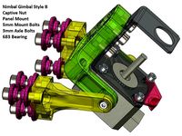
Nimble Gimbal - Gimbaling Extruder Motor Mount for Zesty Nimble by slonold
...?). with the x60 i went with a 0.3mm nozzle and 0.2mm extrusion width, 3 perimeters, 0.125 layer height and 5 top/bottom layers.
thingiverse
free
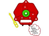
Prometheus Mount for SeeMeCNC Rostock Ball Joint Platform +/- Accelerometer Option by slonold
...ive to the clamp plate like a clam shell.
be sure to seat bowden tube and insert ptc retainer before mounting accelerometer board
thingiverse
free

PanelDue 5" and Duet 2 Mounts for SeeMeCNC Rostock Max V2 by slonold
...phery of the onyx bed. some tape to hold the bed and template down will be your friend whilst you outline the bed plate cut out.
thingiverse
free
Nimble Gimbal For 2020 Delta Frame by quadcells
...i saw slonold's nimble gimbal and liked the idea. slonold did a great job on his design. i needed...
thingiverse
free
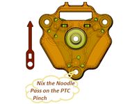
Nimble Gnu - System to Adapt the Zesty Nimble Extruder to a Prometheus V2 Hotend Mounted to a SeeMeCNC Balljoint Effector Platform with Accelerometer Probe PCB by slonold
...ter, strap down the whip.
remember to revisit your slicer retraction settings. it is a whole new world without the bowden tube.
thingiverse
free
Zesty Nimble V2 Breech Replica by kulfuerst
...p3 - bearing offset by 0.3 mm i like slonold#39;s naming system and adapted it here. i have not...
Seemecnc
thingiverse
free

Rostock hotend seemecnc by Wrangler
...rostock hotend seemecnc by wrangler
thingiverse
this thing was made to connect hotend seemecnc to rostock platform.
thingiverse
free

SeeMeCNC Keychain by johnoly99
...seemecnc keychain by johnoly99
thingiverse
no mas!
thingiverse
free

SeeMeCNC Rocket by johnoly99
...seemecnc rocket by johnoly99
thingiverse
no mas!
thingiverse
free
SeeMeCNC 3D Printer Model by ReginaFabricam
...seemecnc 3d printer model by reginafabricam
thingiverse
this is a model of the seemecnc orion delta 3d printer
thingiverse
free
SeeMeCNC H2 NamePlate (Blank) by CapperLabs
...seemecnc h2 nameplate (blank) by capperlabs
thingiverse
seemecnc h2 nameplate without any lettering autocad drawing and .stl
thingiverse
free

SeeMeCNC Plastic Bearings by johnoly99
...seemecnc plastic bearings by johnoly99
thingiverse
no mas!
thingiverse
free
Mosquito for SeeMeCNC Artemis by emoser
...and some rostock printeres.
you will need https://www.sliceengineering.com/collections/accessories/products/threaded-stem-adapter
thingiverse
free
SeeMeCNC EZstruder cooler by Disconnector
...r on my seemecnc rostock max was running very hot (like burn my hand hot!) so i designed a dual 40mm fan mount. all cool now :-)
thingiverse
free

SeeMeCNC H-1 90 Degree Clamp by johnoly99
...seemecnc h-1 90 degree clamp by johnoly99
thingiverse
seemecnc h-1 90 degree clamp
thingiverse
free

SeeMeCNC H-1 Table by johnoly99
...seemecnc h-1 table by johnoly99
thingiverse
no mas!
X1
design_connected
$11

X1
...x1
designconnected
dränert x1 chairs computer generated 3d model. designed by oswald mathias ungers.
3ddd
$1
Leica X1
...leica x1
3ddd
leica , фотоаппарат
leica x1 profi
turbosquid
$15

sofa x1
...turbosquid
royalty free 3d model sofa x1 for download as max on turbosquid: 3d models for games, architecture, videos. (1283096)
3ddd
$1

Francis Francis X1
...francis francis x1
3ddd
кофемашина
кофемашина francis francis x1
3d_export
$5

X1 3D Model
...x1 3d model
3dexport
x1
x1 3d model download .c4d .max .obj .fbx .ma .lwo .3ds .3dm .stl gorgsalvatore 106035 3dexport
turbosquid
$55

Nokia X1
... available on turbo squid, the world's leading provider of digital 3d models for visualization, films, television, and games.
turbosquid
$13

Nokia X1
... available on turbo squid, the world's leading provider of digital 3d models for visualization, films, television, and games.
turbosquid
$1
X1 Airplane
... available on turbo squid, the world's leading provider of digital 3d models for visualization, films, television, and games.
3d_export
$55

Nokia X1 3D Model
...nokia x1 3d model
3dexport
nokia x1 phone smartphone mobile
nokia x1 3d model fedia 45159 3dexport
3ddd
$1

Wood x1
...wood x1
3ddd
размер 1024-1024 бесшовная 8-)
Tension
3d_export
$5
adjustable tension lock
...adjustable tension lock
3dexport
adjustable tension lock
turbosquid
$5
tension ring
...oyalty free 3d model tension ring for download as fbx and stl on turbosquid: 3d models for games, architecture, videos. (1553452)
turbosquid
$3

Tension Chair
...free 3d model tension chair for download as obj, c4d, and fbx on turbosquid: 3d models for games, architecture, videos. (1251503)
3d_export
$5
transformador de tension
...transformador de tension
3dexport
transformador de tension entrada 460vac salida 220vac marca audax
turbosquid
$20
Motorbike Chain Tensioner
...y free 3d model motorbike chain tensioner for download as stl on turbosquid: 3d models for games, architecture, videos. (1428322)
turbosquid
$25
TENSION-WOOD-CHAIR
... available on turbo squid, the world's leading provider of digital 3d models for visualization, films, television, and games.
turbosquid
$25

tension-bentwood-chair
... available on turbo squid, the world's leading provider of digital 3d models for visualization, films, television, and games.
turbosquid
$19
Tension engagement ring
...n engagement ring for download as obj, fbx, 3dm, dwg, and stl on turbosquid: 3d models for games, architecture, videos. (1491631)
3d_export
$10

Ruby Tension set Ring 3D Model
...ruby tension set ring 3d model
3dexport
tension set ruby ring in 18k
ruby tension set ring 3d model rehansheikh 25254 3dexport
turbosquid
$20
Superficial Tension Exp. Image.max
... available on turbo squid, the world's leading provider of digital 3d models for visualization, films, television, and games.
Extrusion
turbosquid
free

aluminum extrusion profiles
...free 3d model aluminum extrusion profiles for download as max on turbosquid: 3d models for games, architecture, videos. (1381707)
turbosquid
$5
Cable Cover Extrusion
... available on turbo squid, the world's leading provider of digital 3d models for visualization, films, television, and games.
3d_export
free

30 x 30 extrusion
... x 30 x 40.sldprt<br>30 x 30 x 50.sldprt<br>30 x 30 x 606.sldprt<br>the sketch.sldprt<br>30 x 30 x 40.stl
3d_export
$300
melt-blown fabric extrusion molding machine
...an email to me.<br>designed with solidworks 2017, render with photoview 360<br>**************************************
3d_export
$5

Spaceship - Galaxy Crusher
...with a more ominous twist. it has lots of extrusion and cubes and comes with a whopping 4k texture,...
3d_export
$20

1600 Meltblown cloth production line set drawing CAD
...width of 1600mm. the steel structure frame, feeding host, extrusion screw, heating system, screen changer, metering pump, melting it...
3d_export
$5

one-eyed scary virus
...cinema, the body relief is formed by the standard extrusion noise. the eye texture is...
3d_export
$20
GE TF34 Fan Blade and Nose Cone
...and appropriately sized fillet features are provided.<br>also, a threaded extrusion profile is provided on the fan blade component and...
3d_export
$10

glue injection machine
...injection technology. the ordinary glue injection machine is screw extrusion type, and its instantaneous pressure can reach more than...
3d_export
$1000
bead triangle adhesive laminating machine
...a triangular rubber head with the shape required for extrusion the rear end of the extruder is also provided...
Joint
turbosquid
$5

Joint
...turbosquid
royalty free 3d model joint for download as blend on turbosquid: 3d models for games, architecture, videos. (1179882)
3d_export
$5
joint handle
...joint handle
3dexport
joint handle
3d_export
$5
knuckle joint
...knuckle joint
3dexport
this is a 3d model of knuckle joint
3d_export
$5
Knuckle Joint
...knuckle joint
3dexport
industry use knuckle joint
3ddd
$1
PENTA Joint
...penta joint
3ddd
penta
http://www.lampcommerce.com/en/catalogue/brands/penta-light/joint-floor-lamp
turbosquid
$49
Joint | Project
...squid
royalty free 3d model joint | project for download as on turbosquid: 3d models for games, architecture, videos. (1297983)
turbosquid
$10

universal joint
...squid
royalty free 3d model univresal joint for download as on turbosquid: 3d models for games, architecture, videos. (1309400)
turbosquid
$15

Joint Ashtray
...squid
royalty free 3d model joint ashtray for download as ma on turbosquid: 3d models for games, architecture, videos. (1199702)
turbosquid
$5

Unrolled joint
...e 3d model unrolled joint for download as blend, obj, and stl on turbosquid: 3d models for games, architecture, videos. (1577889)
3d_export
$5
Cardan Joint 3D Model
...cardan joint 3d model
3dexport
cardan joint
cardan joint 3d model fau 71171 3dexport
Belt
turbosquid
$9
Belt conveyor belt
...t conveyor belt for download as 3ds, ige, obj, stl, and sldas on turbosquid: 3d models for games, architecture, videos. (1226546)
3d_export
$6
belt
...d then comes off and fastens at the front of the seat. version: 2015 units: millimetres x-form: yes polys: 120 950 verts: 163 944
3d_export
$7
belt grinder
...belt grinder
3dexport
belt grinder
3d_export
$5
Belt conveyor
...belt conveyor
3dexport
belt conveyor
3ddd
$1
column belt
...column belt
3ddd
колонна
column belt
turbosquid
$5
Belt
... available on turbo squid, the world's leading provider of digital 3d models for visualization, films, television, and games.
3d_ocean
$5
Leather Belt
...ather belt is created in 3dsmax 2011 and rendered with vray 1.5 and it has all the texture included with the multiple obj format.
3d_ocean
$5
Belt Ring
...belt ring
3docean
belt jewelry ring
belt ring 3d model. total weight 3.5 gram & 1.1 stone size. 3dm and obj file format.
design_connected
$11
Belt Round
...belt round
designconnected
meridiani belt round computer generated 3d model. designed by parisio, andrea.
design_connected
$11
Belt Oval
...belt oval
designconnected
meridiani belt oval computer generated 3d model. designed by parisio, andrea.
Truck
3d_export
$8

truck
...truck
3dexport
truck
archibase_planet
free

Truck
...truck
archibase planet
truck truck crane car
truck toyota n071013 - 3d model (*.gsm+*.3ds) for exterior 3d visualization.
archibase_planet
free

Truck
...truck
archibase planet
truck lorry car
truck - 3d model (*.gsm+*.3ds) for exterior 3d visualization.
archibase_planet
free

Truck
...truck
archibase planet
truck lorry car
truck n260213 - 3d model (*.gsm+*.3ds) for exterior 3d visualization.
3d_export
$5

truck
...truck
3dexport
3d model of a truck, made for optimus prime!
3d_ocean
$19
Truck
...truck
3docean
four-wheel max truck
precision four-wheel drive truck with mud mask effect, the door can be opened
archibase_planet
free

Truck
...truck
archibase planet
truck car broken car lorry
truck broken - 3d model (*.gsm+*.3ds) for exterior 3d visualization.
archibase_planet
free

Truck
...truck
archibase planet
truck lorry autotruck
truck kenworth t600 n280113 - 3d model (*.gsm+*.3ds) for exterior 3d visualization.
archibase_planet
free
Truck
...
archibase planet
truck freightliner lorry car
truck freightliner n200314 - 3d model (*.gsm+*.3ds) for exterior 3d visualization.
archibase_planet
free

Truck
...truck
archibase planet
truck lorry autotruck
truck 4 eu n160614 - 3d model (*.gsm+*.3ds) for exterior 3d visualization.
Ball
turbosquid
$5

Ball on a Ball
...uid
royalty free 3d model ball on a ball for download as obj on turbosquid: 3d models for games, architecture, videos. (1484719)
archibase_planet
free

Ball
...ball
archibase planet
ball golf ball
ball - 3d model (*.gsm+*.3ds) for 3d visualization.
3d_export
$5

ball
...ball
3dexport
ball
archibase_planet
free

Ball
...ball
archibase planet
ball football soccer ball
ball n100714 - 3d model (*.gsm+*.3ds+*.max) for exterior 3d visualization.
3d_export
$5

ball
...ball
3dexport
soccer ball
archibase_planet
free

Ball
...ball
archibase planet
ball football
ball n100914 - 3d model (*.gsm+*.3ds+*.max) for 3d visualization.
3d_ocean
$5

Snooker Balls
... set balls snooker snooker balls white ball yellow ball
set snooker balls format include : .c4d .3ds .obj build in cinema 4d r13
3d_export
free

ball
...ball
3dexport
this is 3d model ball's
3d_ocean
$2

Soccer Ball
...soccer ball
3docean
ball red and yellow ball red ball soccer ball
a gorgeous red and yellow seamless soccer ball
3d_ocean
$5

Billard Balls
...low poly billiard balls. numbering from 1 to 15 plus the cue ball. each of the balls excluding the cue ball has a 4k texture map.
Adjust
3d_ocean
$7
Adjustable Wrench
...adjustable wrench
3docean
adjustable wrench highly detailed wrench
highly detailed adjustable wrench.
3ddd
$1
Adjustable Stool
...adjustable stool
3ddd
табурет
wooden adjustable stool.
3d_ocean
$20

Adjustable Gym Bench
...st adjustable bench black equipement gym gymnastic indoor silver sport workout
3d model of black and silver adjustable gym bench.
3d_ocean
$20
Adjustable Gym Bench
...st adjustable bench black equipement gym gymnastic indoor silver sport workout
3d model of black and silver adjustable gym bench.
3d_ocean
$16

Adjustable Weight Bench
...arbell bench black equipement gym gymnastic indoor sport weight workout
3d model of black adjustable weight bench with a barbell.
turbosquid
$5

Adjustable wrench
...
royalty free 3d model adjustable wrench for download as fbx on turbosquid: 3d models for games, architecture, videos. (1313414)
3d_export
$5
adjustable tension lock
...adjustable tension lock
3dexport
adjustable tension lock
turbosquid
$1

Adjustable Wrench
...free 3d model adjustable wrench for download as obj and blend on turbosquid: 3d models for games, architecture, videos. (1446736)
turbosquid
$1

Adjustable Wrench
...y free 3d model adjustable wrench for download as c4d and fbx on turbosquid: 3d models for games, architecture, videos. (1379022)
3d_export
$5
Adjustable key
...adjustable key
3dexport
System
archibase_planet
free
System
...m
archibase planet
fire alarm system fire alarm box
security light system - 3d model (*.gsm+*.3ds) for interior 3d visualization.
archibase_planet
free
Spider system
...stem spider glass system
spider system to fix glass stefano galli n050912 - 3d model (*.gsm+*.3ds) for interior 3d visualization.
3ddd
$1
Euforia System
...euforia system
3ddd
euforia
euforia system
3d_export
$50
Roof system Truss system 3D Model
...oof system truss system 3d model
3dexport
roof system truss truss stage
roof system truss system 3d model aleksbel 38970 3dexport
3ddd
$1
DVD System
...dvd system
3ddd
dvd , schneider
dvd system
design_connected
free

Seating system
...seating system
designconnected
free 3d model of seating system
3d_export
$5

solar system
...solar system
3dexport
solar system in c4d, with 8k nasa textures
3ddd
$1
Quanta System
...quanta system
3ddd
медицина
quanta system.
лазерное оборудование для медицинских центров
3d_export
$15
solar system
...nd the other the sun, the earth and the moon, the latter has an animation with camera movement included, the files are in spanish
3d_export
$14

missile system
...missile system
3dexport
1
turbosquid
$69

armchairs(1)(1)
... available on turbo squid, the world's leading provider of digital 3d models for visualization, films, television, and games.
turbosquid
$15
ring 1+1
... available on turbo squid, the world's leading provider of digital 3d models for visualization, films, television, and games.
turbosquid
$10
chair(1)(1)
... available on turbo squid, the world's leading provider of digital 3d models for visualization, films, television, and games.
turbosquid
$8

Chair(1)(1)
... available on turbo squid, the world's leading provider of digital 3d models for visualization, films, television, and games.
turbosquid
$2

RING 1(1)
... available on turbo squid, the world's leading provider of digital 3d models for visualization, films, television, and games.
turbosquid
$1
house 1(1)
... available on turbo squid, the world's leading provider of digital 3d models for visualization, films, television, and games.
turbosquid
$1

Table 1(1)
... available on turbo squid, the world's leading provider of digital 3d models for visualization, films, television, and games.
turbosquid
$59

Formula 1(1)
...lty free 3d model formula 1 for download as max, fbx, and obj on turbosquid: 3d models for games, architecture, videos. (1567088)
design_connected
$11

No 1
...no 1
designconnected
sibast no 1 computer generated 3d model. designed by sibast, helge.
turbosquid
$2
desert house(1)(1)
...3d model desert house(1)(1) for download as 3ds, max, and obj on turbosquid: 3d models for games, architecture, videos. (1055095)