GrabCAD

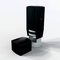
Automatic Valve Carbon Filter
by GrabCAD
Last crawled date: 1 year, 11 months ago
Type F75 series Runxin Valve.
1.1. Main Application & Applicability
Used for filtering water treatment systems
Be suitable for Residential filtering system
Swimming pool filtering equipment (F75A1/53510, F75B1/53510B)
Carbon filter or sand filter in RO pretreatment filtering system
1.2. Product Characteristics
>Simple structure and reliable sealing
It adopts hermetic head faces with high degree pottery and corrosion resistance for
opening and closing. It combines with Service, Backwash, and Fast Rinse.
No water pass the valve in rinsing in single tank type
>Manual function
Realize rinsing immediately by pressing 0 at any time.
>Long outage indicator
If outage overrides 3days, the time of day indicator QQ will flash to remind people to reset new time of day. The other set parameters do not need to reset. The process will continue to work after power on.
>LED dynamic screen display
The stripe on dynamic screen flash, it indicates the control valve is in service; otherwise, it is in rinsing cycle.
>Buttons lock
No operations to buttons on the controller within 1 minute, button lock indicator light on which represent buttons are locked. Before operation, press and hold the 00 and 0 buttons for 5 seconds to unlock. This function can avoid incorrect operation. >Rinsing frequence
It could set up multiple risings, which means several times of backwash and fast rinse but one time of service. It is much better for cleaning the filter materials.(Refer to P25 for more details.) >There are two kinds of time clock types
Time clock type valve can be chosen to be service by hours ,by dialing the red switch on main control board to " 1" (Refer to the Figure 3-1). Pointing to "ON" mean the time clock type service by days; "1" means the time clock type service by hours. (Attention: after dialing the switch, please restart the power)
>Interlock function
It has a function of interlock to realize only one valve in rinsing, but the other valves are in service while there are several valves parallel in system. In multi-steps treatment systems such as RO pre-treatment, when several valves are in series, there is only one valve in rinsing to ensure pass water all the times while different valves in rinsing. (Application refer to Figure 3-10)
Signal output
There is a signal output connector on main control board. It is for controlling external wiring( Refer to Figure, from Figure3-2 to Figure 3-9).
There are two kinds of output modes. b-01 Mode: Turn on start of regeneration and shut off end of regeneration; b-02 Mode: Signal available only intervals of rinsing cycles and in service.
b-01 b-02
Y N
Remote handling input
This connector can receive external signal, used together with PLC, and computer etc. to control the valve. (Application refer to Figure3-12 )
Pressure relief output
The valve will cut off feeding water to drain line when it switches in rinsing cycles (Same as signal output b-02). Thus in some water treatment system, e.g. Deep Well, one booster pump was installed on the inlet to increase the system water feeding pressure, this cut-off will cause pressure on inlet rising too fast to damage the valve. Pressure Relief Output can be used to avoid this problem. (Application refer to Figure3-11).
All parameters can be modified
According to the water quality and usage, the parameters in the process can be adjusted.
Similar models
3dwarehouse
free

Splash Filter system, Approach by Splash Nepal(Prabhav)
...valves for controlling flow amount - pressure gauges for maintaining pressure in flow - water meter to record the amount of water
grabcad
free

Water Control Valve. su kontrol valfi.
...at a preset value. a pressure sustaining valve is similar to a pressure reducing valve but governs the pressure...
grabcad
free

AFR 2000
...afr 2000
grabcad
pneumatic filter air treatment unit pressure regulator compressor reducing valve oil water separation
thingiverse
free

Valve Holder for Water Filtration System
...for a valve that for me controls my water filter system, the arm is ~5 inches and the attachment is approx 0.9" in diameter.
grabcad
free

1" Pressure Reducing Valve (PRV)
...1" pressure reducing valve (prv)
grabcad
1" pressure reducing valve (prv)
stainless steel - water application
3dwarehouse
free

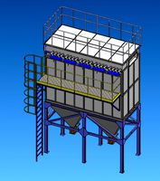
Wastewater Treatment Plant (Advanced Wastewater Treatment)
...lant (advanced wastewater treatment)
3dwarehouse
6 mgd dual media #backwash #dual #filter #media #plant #pump #wastewater #water
grabcad
free

valve tree DN50
...50
grabcad
this valve tree controlls an auotomatic backwashfilter in following modes:
filtering, backwashing, lowering, filling.
grabcad
free

Pressure Relief Valve
...abcad
a relief valve or pressure relief valve (prv) is a type of safety valve used to control or limit the pressure in a system.
grabcad
free

Pressure Relief valve
...rabcad
a relief valve or pressure relief valve (prv) is a type of safety valve used to control or limit the pressure in a system
grabcad
free

Steam Valve
...ed water vapour. the major application of valves with steam is to reduce the pressure of the inlet steam for process application.
Carbon
3d_ocean
$2

Carbon Textures
...usty shiny tga tileable
a pack of 5 carbon textures. tileable. 512×512 pixel sized. jpg , tga image format given. stay connected
design_connected
$16

Carbon Chair
...carbon chair
designconnected
moooi carbon chair chairs computer generated 3d model. designed by marcel wanders.
3ddd
$1
Carbon touring desk
... tonino lamborghini casa , стол
tonino lamborghini casa carbon touring desk
turbosquid
$1
carbonic acid
...id
royalty free 3d model carbonic acid for download as blend on turbosquid: 3d models for games, architecture, videos. (1517834)
design_connected
$7

Carbon Shagreen Box
...carbon shagreen box
designconnected
carbon shagreen box computer generated 3d model.
turbosquid
$90

Carbon NanoSheet
... available on turbo squid, the world's leading provider of digital 3d models for visualization, films, television, and games.
turbosquid
$90
Carbon Nanotube
... available on turbo squid, the world's leading provider of digital 3d models for visualization, films, television, and games.
turbosquid
$40

carbon nanosheet
... available on turbo squid, the world's leading provider of digital 3d models for visualization, films, television, and games.
turbosquid
$38

Carbon Planet
... available on turbo squid, the world's leading provider of digital 3d models for visualization, films, television, and games.
turbosquid
$29

Carbon dioxide
... available on turbo squid, the world's leading provider of digital 3d models for visualization, films, television, and games.
Filter
3d_export
$10
cartridge filter
...cartridge filter
3dexport
cartridge filter
3d_export
$6
Bag filter
...bag filter
3dexport
bag filter
3d_export
$10

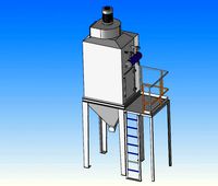
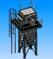
of dust filter
...of dust filter
3dexport
3d model of dust filter
3d_export
$10

of bag filter
...of bag filter
3dexport
3d model of bag filter
3d_export
$7

of bag filter
...of bag filter
3dexport
3d model of bag filter
turbosquid
$20

Filter
...ty free 3d model filter for download as ma, max, obj, and fbx on turbosquid: 3d models for games, architecture, videos. (1512887)
3d_export
$10
bag filter
...he ash hopper. when the gas containing fine dust passes through the filter material, the dust is retained and the gas is purified
3ddd
$1

UFI Filter
...ufi filter
3ddd
фильтр , ufi
ufi oil filter
turbosquid
$30

Filter
... available on turbo squid, the world's leading provider of digital 3d models for visualization, films, television, and games.
turbosquid
$5

filters
... available on turbo squid, the world's leading provider of digital 3d models for visualization, films, television, and games.
Automatic
archibase_planet
free
Automat
...automat
archibase planet
automat equipment
automat n190510 - 3d model (*.gsm+*.3ds) for interior 3d visualization.
3d_export
$17

Automatic wire bending machine wire automatic bending machine
...atic wire bending machine wire automatic bending machine
3dexport
automatic wire bending machine, wire automatic bending machine
archive3d
free

Automat 3D Model
...ive3d
automat equipment
automat n190510 - 3d model (*.gsm+*.3ds) for interior 3d visualization.
3d_export
$20

Design of automatic laminator
...design of automatic laminator
3dexport
design of automatic laminator
3d_export
$6
Automatic soldering machine
...automatic soldering machine
3dexport
automatic soldering machine
turbosquid
$20

automatic rifle
...id
royalty free 3d model automatic rifle for download as fbx on turbosquid: 3d models for games, architecture, videos. (1163137)
turbosquid
$9

automatic gun
...yalty free 3d model automatic gun for download as max and obj on turbosquid: 3d models for games, architecture, videos. (1226948)
turbosquid
$5

Automatic Knife
...lty free 3d model automatic knife for download as max and fbx on turbosquid: 3d models for games, architecture, videos. (1378253)
turbosquid
$15
Automatic Stamp
...d model automatic stamp for download as ma, max, fbx, and obj on turbosquid: 3d models for games, architecture, videos. (1569569)
turbosquid
$1
flashlight for automat
...flashlight for automat for download as 3ds, max, obj, and fbx on turbosquid: 3d models for games, architecture, videos. (1314717)
Valve
3d_export
$5
Valve
...valve
3dexport
diverter valve
3d_export
$5
valve
...valve
3dexport
this is a 3d model of a valve available in all formats.
3d_export
free
valve
...valve
3dexport
simple valve 3d model, more free models here:
3d_export
$20

gate valve
...gate valve
3dexport
gate valve
3d_export
$10

stop valve
...stop valve
3dexport
stop valve
3d_export
$5
ball valve
...ball valve
3dexport
ball valve
turbosquid
$14

Valve
...e
turbosquid
royalty free 3d model valve for download as c4d on turbosquid: 3d models for games, architecture, videos. (1217741)
3ddd
$1
valve 02
...valve 02
3ddd
клапан
water valve
3ddd
$1

Valve 01
...valve 01
3ddd
клапан
water valve
turbosquid
$19

Valve
...royalty free 3d model valve for download as ige, obj, and stl on turbosquid: 3d models for games, architecture, videos. (1425806)