Thingiverse
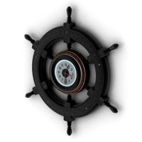
Auto-winding drum for weight-driven clock
by Thingiverse
Last crawled date: 4 years, 3 months ago
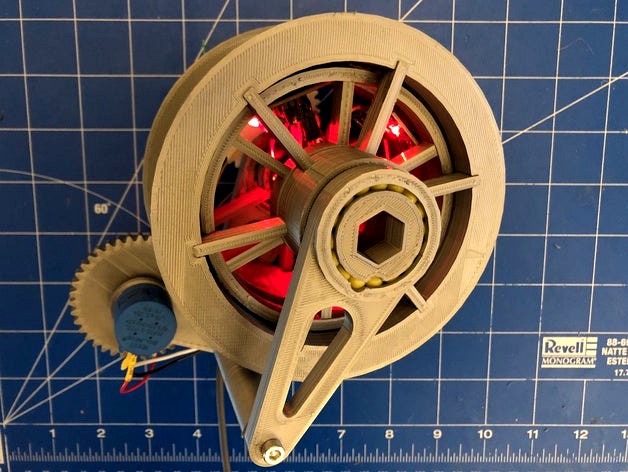
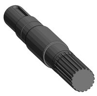
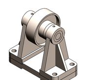
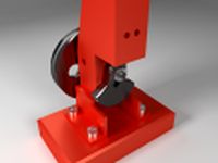
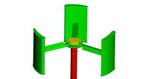
This is a weight drum for a mechanical clock, incorporating an automatic winding system using a stepper motor and Ardunio. It allows a clock to be fully weight-driven and continue to run even while the weight is being wound by a motor.
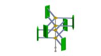
The weight cord is wound around the outer drum, with torque transferred to the inner drum via a freewheel. The inner drum is geared to a separate escapement mechanism to power the clock. The motor sits inside the inner drum and engages a gear on the outer drum. During winding, the motor turns the outer drum relative to the inner drum, with torque now transferred to the inner drum via the motor instead of the freewheel. An external potentiometer measures the position of the outer drum to determine when to start and stop winding.
I used it to drive A26's triaxial tourbillon (https://www.thingiverse.com/thing:2761730), connected to my planetary clock (https://www.thingiverse.com/thing:4055592). Fair warning, the motor's maximum power is roughly equal to the power required to drive the tourbillon/clock system, meaning the motor stalls quite a bit and sometimes can't make forward progress. I'd like to change it to a NEMA 14 or larger in the future (should be enough room).
Components used:
Arduino Nano 5V
28BYJ-48 stepper motor and driver board
12.5mm slip ring. For sizing reference, I used this one: https://www.amazon.com/gp/product/B07H2SRMXP/ref=ppx_yo_dt_b_asin_title_o02_s00?ie=UTF8&psc=1
10-turn potentiometer. For sizing reference, I used this one: https://www.amazon.com/gp/product/B079JN626M/ref=ppx_yo_dt_b_asin_title_o02_s00?ie=UTF8&psc=1
M3 screws, various lengths
6mm Airsoft pellets
Basic assembly info (I recommend reviewing the Tinkercad model before proceeding):
Make electrical connections between Arduino, driver board, and slip ring (see below).
File all bearing races to remove any burrs.
Attach drivegear to motor.
Attach motor and freewheel to innerdrum with M3 screws. Do not tighten.
Attach slip ring flange to innerdrumrearspokes with M3 screws. Use the side where the spokes are flush with the inner ring.
Insert innerdrumrearspokes into framerear. Align the bearing insertion holes (on the side opposite the slip ring) and insert 6mm pellets. Ensure that the assembly turns freely.
Attach Arduino and driver board to innerdrum with hot glue. Use the larger diameter half of the slip wing (the one attached to the flange).
Insert innerdrumrearspokes assembly into innerdrum. If the fit is too loose, add a few dabs of hot glue.
Insert 6 pellets into the cutouts on freewheel. They should stay in place if the freewheel is oriented vertically, otherwise you can wrap them with a piece of paper before attaching the outer drum.
Attach outerdrumgear to outerdrum using the alignment pegs. Glue in place.
Slide outerdrum over innerdrum. Ensure that the freewheel functions properly. As viewed from the front side, the outer drum should engage the inner drum when spinning clockwise and should spin freely in the other direction.
Align the bearing insertion holes between innerdrum and outerdrum, and insert 6mm pellets. Ensure that the assembly turns freely.
Insert pellets between outerdrum and freewheel (middle race on freewheel).
Adjust the position of the motor to achieve a proper mesh between drivegear and outerdrum. Tighten motor screws.
Insert freewheel into framefront and insert pellets.
Attach framebot using M3 screws. Do not tighten.
Attach pot to framebot and add positiongear. Secure with M2 setscrew.
Rotate framebot to get a proper mesh between positiongear and outerdrumgear. Tighten framebot screws.
Attach framerear to mounting surface and escapement mechanism.
Complete connections between potentiometer, slip ring, and power (5V).
Arduino info:
See stepper.ino for example code. You will likely need to customize the values for RPM and turns.
There are many tutorials on connecting a stepper motor to an Ardunio. Example: https://www.seeedstudio.com/blog/2019/03/04/driving-a-28byj-48-stepper-motor-with-a-uln2003-driver-board-and-arduino/
Tinkercad:https://www.tinkercad.com/things/gsawV8K9iF8-freewheel-drumhttps://www.tinkercad.com/things/1DgcbQbeJzv-freewheel-drum-assembly
Freewheel design by Corona688: https://www.thingiverse.com/thing:207389
Similar models
thingiverse
free
Screw Driver Set With Storage by AmericanEngineering
...djusting your steppers on your 3d printer or adjusting potentiometers on circuits, this will ensure nothing gets short circuited.
grabcad
free

Table drum clock on stepper motors.
...table drum clock on stepper motors.
grabcad
table drum clock on stepper motors.
thingiverse
free

Gear and Mount for Slip Ring by AndonRT
...be gripped with a pair of pliers or something similar until i update...
grabcad
free

Motor driver L9110
...motor driver l9110
grabcad
motor driver arduino compatible used for driving 2 dc motors or 1 stepper motor.
grabcad
free

TB6600 Stepper motor driver by taitran
... output 4a peak current, which is enough for the most of stepper motors. the stepper driver supports speed and direction control.
grabcad
free

TB6600 stepper motor driver by prodes
... output 4a peak current, which is enough for the most of stepper motors. the stepper driver supports speed and direction control.
grabcad
free

TB6600 Stepper motor driver by Tdesign
... output 4a peak current, which is enough for the most of stepper motors. the stepper driver supports speed and direction control.
grabcad
free

TB6600 Stepper motor driver by Taitran Technic
... output 4a peak current, which is enough for the most of stepper motors. the stepper driver supports speed and direction control.
grabcad
free

TB6600 stepper motor driver by proma
... output 4a peak current, which is enough for the most of stepper motors. the stepper driver supports speed and direction control.
thingiverse
free
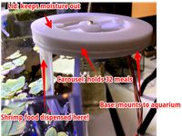
Automatic Pellet Feeder for Shrimp Aquarium
...e once so you know it is working
power arduino and stepper motor assembly (5v usb or power supply)
go on vacation
shrimp get fed
Driven
turbosquid
$50
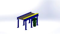
CHAIN DRIVEN CONVEYOR
... available on turbo squid, the world's leading provider of digital 3d models for visualization, films, television, and games.
3d_export
free
driven shaft of the lump crusher
...driven shaft of the lump crusher
3dexport
3d_export
$27
n95 full servo driven mask printer
...n95 full servo driven mask printer
3dexport
n95 full servo driven mask printer
turbosquid
$16
(Project) Food packing helper machine with holding clamp and press table driven by an actuator
... available on turbo squid, the world's leading provider of digital 3d models for visualization, films, television, and games.
3d_export
$47
the fifth generation of one driven two new mask machine
...ing, lamination, pressing, ear band tapping, ultrasonic, etc. the structure of the model is detailed, including model parameters.
3d_export
$15

industrial belt-driven air cooler
...leaning up necessary, just drop your models into the scene and start rendering/texturing. no special plugin needed to open scene.
3d_export
free

golf cart
...golf cart 3dexport golf cart for golfers to be driven in...
3d_export
$10
design and assembly of pulley
...pulley 3d model which is used for drive and driven ...
archive3d
free

Windmill 3D Model
...windmill 3d model archive3d wind turbine wind-driven powerplant wind-electric set windmill n181208 - 3d model (*.gsm+*.3ds)...
3d_export
$30
Compressed Air Engine 3D Model
...motor flywheel shaft camshaft piston valve block engineering compressed-air driven compressed air engine 3d model zenmunster 92451...
Drum
3d_export
$5

drums
...drums
3dexport
drums
3d_ocean
$20
Drums
...iled model of drums. charleston,bass drum, tamtam drums, cymbal,etc. available in .blend, .obj, and .lwo format. ready for render
archibase_planet
free
Drum
...hibase planet
drum musical instrument tambour drum kit
drum taiko n091115 - 3d model (*.gsm+*.3ds) for interior 3d visualization.
design_connected
$9

Drum
...drum
designconnected
brent comber drum computer generated 3d model. designed by comber, brent.
turbosquid
$4

Drum 7 Drum 12
... model drum 7 drum 12 for download as max, max, fbx, and obj on turbosquid: 3d models for games, architecture, videos. (1641795)
3d_export
$15

Conga Drum
...conga drum
3dexport
conga drums
3d_export
$10
electro drums
...electro drums
3dexport
electro drums
3d_export
$5
electric drums
...electric drums
3dexport
electric drums
turbosquid
$1

Drum
...turbosquid
royalty free 3d model drum for download as blend on turbosquid: 3d models for games, architecture, videos. (1480093)
turbosquid
$1

Drums
...s
turbosquid
royalty free 3d model drums for download as max on turbosquid: 3d models for games, architecture, videos. (1240112)
Winding
design_connected
$4

Wind
...wind
designconnected
emmemobili wind dining tables computer generated 3d model. designed by chiara vaghi.
3d_ocean
$4

Wind Turbine
...n
and render setup turbine wind
wind turbine, modeled with cinema4d r13 , render setup and textured, custom logo for wind turbine
3d_export
$40
wind turbine
...wind turbine
3dexport
wind turbine
3d_export
$40

wind turbine
...wind turbine
3dexport
wind turbine
3d_export
$40
wind turbine
...wind turbine
3dexport
wind turbine
3d_export
$40
wind turbine
...wind turbine
3dexport
wind turbine
3d_export
$40
wind turbine
...wind turbine
3dexport
wind turbine
3d_export
$40
wind turbine
...wind turbine
3dexport
wind turbine
3d_export
$40

wind turbine
...wind turbine
3dexport
wind turbine
3d_export
$40

wind turbine
...wind turbine
3dexport
wind turbine
Clock
3d_ocean
$4

Clock
...clock
3docean
clock hand kitchen clock time watch
a clock
archibase_planet
free

Clock
...clock
archibase planet
clock table clock alarm-clock
clock orange - 3d model (*.gsm+*.3ds) for interior 3d visualization.
archibase_planet
free

Clock
...clock
archibase planet
clock table clock alarm-clock
clock yellow - 3d model (*.gsm+*.3ds) for interior 3d visualization.
archibase_planet
free
Clock
...clock
archibase planet
clock alarm-clock
clock n100707 - 3d model for interior 3d visualization.
archibase_planet
free

Clock
...clock
archibase planet
clock table clock
clock - 3d model (*.gsm+*.3ds) for interior 3d visualization.
archibase_planet
free

Clock
...clock
archibase planet
clock striking clock
clock - 3d model (*.gsm+*.3ds) for interior 3d visualization.
archibase_planet
free

Clock
...clock
archibase planet
clock wall clock
clock 1 - 3d model (*.gsm+*.3ds) for interior 3d visualization.
archibase_planet
free
Clock
...clock
archibase planet
clock wall clock
clock 2 - 3d model (*.gsm+*.3ds) for interior 3d visualization.
archibase_planet
free

Clock
...clock
archibase planet
clock wall clock
clock 3 - 3d model (*.gsm+*.3ds) for interior 3d visualization.
archibase_planet
free

Clock
...clock
archibase planet
alarm clock alarm-clock
clock - 3d model (*.gsm+*.3ds) for interior 3d visualization.
Auto
3d_export
$5

auto
...auto
3dexport
auto
3ddd
$1

auto
...auto
3ddd
max7
turbosquid
$69
AUTO
...to
turbosquid
royalty free 3d model auto for download as obj on turbosquid: 3d models for games, architecture, videos. (1453538)
3d_export
$10

Auto
...auto
3dexport
3d_export
free

auto
...auto
3dexport
3ddd
$1

Auto posters
...auto posters
3ddd
машина
auto posters
turbosquid
$50

auto
... available on turbo squid, the world's leading provider of digital 3d models for visualization, films, television, and games.
turbosquid
$28

Auto
... available on turbo squid, the world's leading provider of digital 3d models for visualization, films, television, and games.
turbosquid
$20
auto
... available on turbo squid, the world's leading provider of digital 3d models for visualization, films, television, and games.
turbosquid
$5
auto
... available on turbo squid, the world's leading provider of digital 3d models for visualization, films, television, and games.
Weight
archibase_planet
free
Weight
...weight
archibase planet
weight
weight n030907 - 3d model for interior 3d visualization.
3ddd
$1
Weighted
...weighted
3ddd
weighted
высота (см)165ширина (см)75
archibase_planet
free

Weight
...weight
archibase planet
weight dumb-bell dumbbell
weight 24 kg n290313 - 3d model (*.gsm+*.3ds) for interior 3d visualization.
3d_export
free
weight
...weight
3dexport
archibase_planet
free

Weight
...weight
archibase planet
gym sport equipments
sport`s weight n010907- 3d model for interior 3d visualization.
turbosquid
$14

Weight
...uid
royalty free 3d model weight for download as max and obj on turbosquid: 3d models for games, architecture, videos. (1197215)
turbosquid
$19

Weight
...alty free 3d model weight for download as , stl, obj, and fbx on turbosquid: 3d models for games, architecture, videos. (1684982)
turbosquid
$4
Weights
...yalty free 3d model weights for download as max, obj, and fbx on turbosquid: 3d models for games, architecture, videos. (1494762)
turbosquid
$6
weights
... free 3d model weights for download as 3ds, obj, c4d, and fbx on turbosquid: 3d models for games, architecture, videos. (1261435)
turbosquid
$3
weight
...free 3d model weight for download as blend, dae, fbx, and obj on turbosquid: 3d models for games, architecture, videos. (1558127)