Thingiverse
Auto-Level Mounts for Ender 3, CR-10, Tevo, etc. by Modmike
by Thingiverse
Last crawled date: 3 years ago
New!
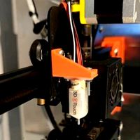
1) Added BL Touch mount V2.0
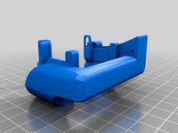
2) Added M8 inductive sensor mount - Big thanks to GroovyDrifter for inspiration!
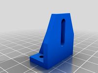
2) Revised SN04 mount to use easier to find M3 20mm bolts
3) Added detailed instructions.
Notes
I have not personally tested the M8 and BL Touch mounts, let me know how they work for you please.
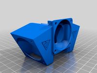
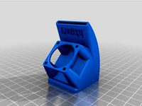
Sensor Mounts
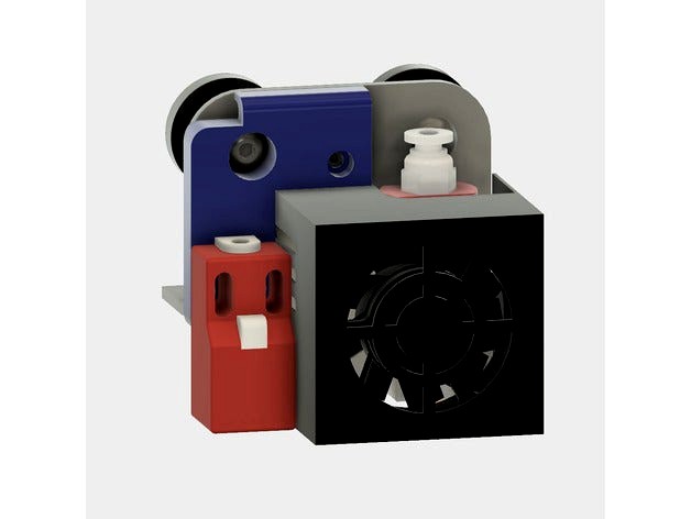
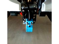
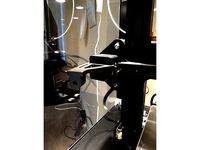
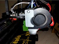
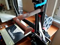
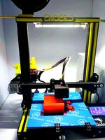
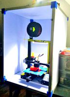
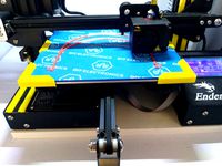
These mounts allow you to add commonly available auto-level sensors to Creality printers such as the CR10, CR10 variants, Ender 2, Ender 3, and Tevo printers that use the stock stock Creality hot end / carriage combinations.
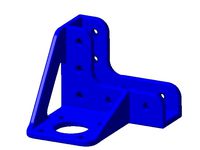
The mounts feature solid mounting points and a wire management clamp along the top to neatly secure and route sensor wires.
All designs are based on the Creality Ender 3 hot end & carriage configuration.
Sensor Selection
I like the SN04 sensors because they are light, robust, and inexpensive. I would avoid the heavier M8 style sensors because their heavier weight could negatively impact print quality, especially at higher speeds.
If you have a glass plate you should get a BL Touch. If you have a thin glass plate on an aluminum bed, an SN04 with an 8mm detection range would probably work.
Required mounting hardware:
SN04: 2X M3 20mm cap or pan head bolt, 2X M3 washers, & 2X M3 Nylock nuts, regular M3s will do in a pinch but will loosen with vibration
BL Touch: 2X M3 10mm cap or pan head bolt. 2X M3 Nylock nuts, 2X M3 washers to shim if necessary, regular M3 nuts will do in a pinch but will loosen with vibration
M8: 1X M3 10mm or 12mm cap or pan head bolt & 1X M3 Nylock nut, regular M3s will do in a pinch but will loosen with vibration.
Sensor performance
While some sensors can work on 5 volts, their minimum input voltage is usually 6V. Using only 5 volts degrades accuracy and shortens detection range, which is a problem if you are using a glass plate.
I highly recommend you power your sensor with 12V or 24V by directly connecting it to your controllers power input terminals. The Ender 3 has a 24V power supply, I am not sure about other Creality printers but they are typically 12V, which also works well.
Firmware
You will need to install a new version of Marlin to enable auto-level capability to your printer. It can be a chore becasue Creality did not install a boot loader. Persevere becasue there are many advantages such as:
1) Adding auto level cpability
2) Adding critical thermal runaway protection to prevent fires
3) Adding useful LCD menus such as bed corner leveling
4) Geting the latest open source version of Marlin and all it's
additional features
5) Most importantly, getting full control of your printer!
I recommend you install Marlin 2.0.x bug fix. Marlin version 1.19 will be the last version for the 1 series. You can download it by going to the following URL and clicking on the "Clone or Download" button, in the upper right hand corner of the page. Select "Download Zip" to download.
https://github.com/MarlinFirmware/Marlin/tree/bugfix-2.0.x
Version 2.0.x requires Platform IO, it does not compile with Arduino IDE. I know this is a real drag but as I said, 1.19 is the end of that branch. If you are ok with 1.19 and familiar with Arduino IDE, then by all means stick with that.
If you want to stay current, you will need to install Platform IO and Atom. Now c'mon, are you a maker or what?!
https://www.letscontrolit.com/wiki/index.php/Tutorial_Install_Platformio
It works great on Mac also! By the way, try to stay away from custom vendor versions provided. They may take up valuable memory you can't spare have trail behind the official version.
Here are a few great video tutorials. I prefer the USBAsp method but most people seem to prefer the Arduino method.
How to flash firmware with USBAsp:
https://www.youtube.com/watch?v=AQX_AEdXqt4
How to flash firmware with an Arduino board:
https://www.youtube.com/watch?v=QWwtbmg_AxQ
How to configure Marlin to fit in limited memory:
https://www.youtube.com/watch?v=2TrGeL8ZdGU&t=18s
Installation
If you are powering the sensor with anything more than 5V (and you really should be), you will need to reduce the sensors signal wire output voltage.
WARNING!
If you do not put a voltage divider or Schottky diode on the sensor's output wire, you WILL BLOW YOUR BOARD!
I initially tried a Voltage divider but they can be tricky to setup becasue most modern sensors already include a 10K pulldown resistor in their circuit. Worse still, they can heat up quite a bit, especially at 24V.
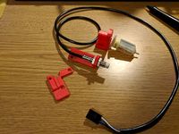
To simplify installation and better protect your controller board, I recommend using a commonly available 1N4148 30V (or more) Schottkey barrier diode. It will stop any current from flowing to your boards signal pin and destroying it. An added benefit is that most diodes fail in the open position, further protecting your board.
I ended up using a Bat85,113 becasue it's what I had on hand.
Wiring
What follows is for the SN04 and M8, the BL-Touch works using the servo pin. Please refer to it's instructions for wiring.
First, make sure you have the right wiring colors for your particular sensor. My color codes may not be the same as yours, although most of them seem similar.
Refer to the included schematic and make sure you have it handy to refer back to easily.
Strip the wires and connect as follows:
Vcc (typically brown) goes to the positive terminal of your power source, such as power supply.
Ground (typically blue, yes I know pretty weird and counter intuitive) goes to the ground (-) of your power source.
Signal (typically black, seriously? What the heck were they thinking?) goes to the diode side with the black stripe. The other end of the diode goes to the signal pin of your controllers Z end stop connector.
I highly recommend you solder the diode to the signal wire and crimp a dupont connector on the other end of the diode for security's sake. If the wire comes loose ,you could have a nice bed crash, don't ask me how I know!
Checking your work
Before connecting the signal wire to your controller, power up and check the amperage at the end of the diode going to the signal pin, it should be 0. If not, you wired it backwards or the diode is shorted.
Now set your multimeter to DC Volts and check the voltage at the signal pin. You might be surprised to see 24V or 12V (voltage will be equal to the power source you used to drive the sensor) coming out of the diode.
This is normal and expected. The diode stops current (amps) not voltage from flowing to the sensor pin, thereby perfectly protetcing your board.
The best way to figure out which of the 2 or 3 pins on your Z endstop is the signal pin, find the schematics. 3 pin connectors typically have the signal pin in the middle, as per typical Ramps boards.
If you can't find the conector, use a multi tester to test each pin. If you get 5V on a 2 pin connector then the other pin is signal. DO NOT connect to 5V.
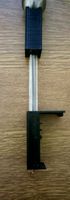
Sensor offsets
You will need to set the probe's physical distance from the nozzle in Marlin so that it knows where the probe is. Set the X & Y offsets according to your probe.
Sensor #define SENSOR_LEFT #define SENSOR_Front
SN04 -40.6 -7.5
BL Touch -40.2 -11.5
M8 -40.2 -3.5
I would also enable safe homing at the centre of the bed to prevent head crashes.In Marlin:
define Z_SAFE_HOMING
The final and MOST CRITICAL step is to determine the Z offset. For some reason this step seems to confuse people the most. There are a multitude of ways to do this and some tutorials are overly complicated, or even incorrect. You do not need to heat the bed for the offset calculation.
The Z offset is the physical distance between the nozzle and the probes detection point. This is usally a negative number. I recommend you do not store this in firmware becasue it can change after a nozzle change, head crash, etc.
From the terminal of your choice, pronterface, S3D or whatever, connect to your board and send the following G-Codes to your printer:
1) M851 Z0 - Makes sure offset is clear
2) G28 - Home
3) G1 Z0 - to make sure head is at true 0
4) M211 S0 - Disable software endstops
5) From the LCD, go to prepare, move Z axis, .1mm
6) Use a piece of paper to adjust height by lowering head
(turn knob left)
7) When the proper height is achieved, read the number on the
display, we will use -.8 for this example. If your value is
higher than 1.2, lower your sensor a little and restart.
8) M851 Z-.8
9) M500 to save
10) M501 to load
11) M2111 S1 - Restore software endstops
12) Exit out of LCD menu back to first screen
Lets double check our work:
13) G28 - Home printer
14) G1 Z0
15) Now test your paper again.
You are done!
1) Added BL Touch mount V2.0
2) Added M8 inductive sensor mount - Big thanks to GroovyDrifter for inspiration!
2) Revised SN04 mount to use easier to find M3 20mm bolts
3) Added detailed instructions.
Notes
I have not personally tested the M8 and BL Touch mounts, let me know how they work for you please.
Sensor Mounts
These mounts allow you to add commonly available auto-level sensors to Creality printers such as the CR10, CR10 variants, Ender 2, Ender 3, and Tevo printers that use the stock stock Creality hot end / carriage combinations.
The mounts feature solid mounting points and a wire management clamp along the top to neatly secure and route sensor wires.
All designs are based on the Creality Ender 3 hot end & carriage configuration.
Sensor Selection
I like the SN04 sensors because they are light, robust, and inexpensive. I would avoid the heavier M8 style sensors because their heavier weight could negatively impact print quality, especially at higher speeds.
If you have a glass plate you should get a BL Touch. If you have a thin glass plate on an aluminum bed, an SN04 with an 8mm detection range would probably work.
Required mounting hardware:
SN04: 2X M3 20mm cap or pan head bolt, 2X M3 washers, & 2X M3 Nylock nuts, regular M3s will do in a pinch but will loosen with vibration
BL Touch: 2X M3 10mm cap or pan head bolt. 2X M3 Nylock nuts, 2X M3 washers to shim if necessary, regular M3 nuts will do in a pinch but will loosen with vibration
M8: 1X M3 10mm or 12mm cap or pan head bolt & 1X M3 Nylock nut, regular M3s will do in a pinch but will loosen with vibration.
Sensor performance
While some sensors can work on 5 volts, their minimum input voltage is usually 6V. Using only 5 volts degrades accuracy and shortens detection range, which is a problem if you are using a glass plate.
I highly recommend you power your sensor with 12V or 24V by directly connecting it to your controllers power input terminals. The Ender 3 has a 24V power supply, I am not sure about other Creality printers but they are typically 12V, which also works well.
Firmware
You will need to install a new version of Marlin to enable auto-level capability to your printer. It can be a chore becasue Creality did not install a boot loader. Persevere becasue there are many advantages such as:
1) Adding auto level cpability
2) Adding critical thermal runaway protection to prevent fires
3) Adding useful LCD menus such as bed corner leveling
4) Geting the latest open source version of Marlin and all it's
additional features
5) Most importantly, getting full control of your printer!
I recommend you install Marlin 2.0.x bug fix. Marlin version 1.19 will be the last version for the 1 series. You can download it by going to the following URL and clicking on the "Clone or Download" button, in the upper right hand corner of the page. Select "Download Zip" to download.
https://github.com/MarlinFirmware/Marlin/tree/bugfix-2.0.x
Version 2.0.x requires Platform IO, it does not compile with Arduino IDE. I know this is a real drag but as I said, 1.19 is the end of that branch. If you are ok with 1.19 and familiar with Arduino IDE, then by all means stick with that.
If you want to stay current, you will need to install Platform IO and Atom. Now c'mon, are you a maker or what?!
https://www.letscontrolit.com/wiki/index.php/Tutorial_Install_Platformio
It works great on Mac also! By the way, try to stay away from custom vendor versions provided. They may take up valuable memory you can't spare have trail behind the official version.
Here are a few great video tutorials. I prefer the USBAsp method but most people seem to prefer the Arduino method.
How to flash firmware with USBAsp:
https://www.youtube.com/watch?v=AQX_AEdXqt4
How to flash firmware with an Arduino board:
https://www.youtube.com/watch?v=QWwtbmg_AxQ
How to configure Marlin to fit in limited memory:
https://www.youtube.com/watch?v=2TrGeL8ZdGU&t=18s
Installation
If you are powering the sensor with anything more than 5V (and you really should be), you will need to reduce the sensors signal wire output voltage.
WARNING!
If you do not put a voltage divider or Schottky diode on the sensor's output wire, you WILL BLOW YOUR BOARD!
I initially tried a Voltage divider but they can be tricky to setup becasue most modern sensors already include a 10K pulldown resistor in their circuit. Worse still, they can heat up quite a bit, especially at 24V.
To simplify installation and better protect your controller board, I recommend using a commonly available 1N4148 30V (or more) Schottkey barrier diode. It will stop any current from flowing to your boards signal pin and destroying it. An added benefit is that most diodes fail in the open position, further protecting your board.
I ended up using a Bat85,113 becasue it's what I had on hand.
Wiring
What follows is for the SN04 and M8, the BL-Touch works using the servo pin. Please refer to it's instructions for wiring.
First, make sure you have the right wiring colors for your particular sensor. My color codes may not be the same as yours, although most of them seem similar.
Refer to the included schematic and make sure you have it handy to refer back to easily.
Strip the wires and connect as follows:
Vcc (typically brown) goes to the positive terminal of your power source, such as power supply.
Ground (typically blue, yes I know pretty weird and counter intuitive) goes to the ground (-) of your power source.
Signal (typically black, seriously? What the heck were they thinking?) goes to the diode side with the black stripe. The other end of the diode goes to the signal pin of your controllers Z end stop connector.
I highly recommend you solder the diode to the signal wire and crimp a dupont connector on the other end of the diode for security's sake. If the wire comes loose ,you could have a nice bed crash, don't ask me how I know!
Checking your work
Before connecting the signal wire to your controller, power up and check the amperage at the end of the diode going to the signal pin, it should be 0. If not, you wired it backwards or the diode is shorted.
Now set your multimeter to DC Volts and check the voltage at the signal pin. You might be surprised to see 24V or 12V (voltage will be equal to the power source you used to drive the sensor) coming out of the diode.
This is normal and expected. The diode stops current (amps) not voltage from flowing to the sensor pin, thereby perfectly protetcing your board.
The best way to figure out which of the 2 or 3 pins on your Z endstop is the signal pin, find the schematics. 3 pin connectors typically have the signal pin in the middle, as per typical Ramps boards.
If you can't find the conector, use a multi tester to test each pin. If you get 5V on a 2 pin connector then the other pin is signal. DO NOT connect to 5V.
Sensor offsets
You will need to set the probe's physical distance from the nozzle in Marlin so that it knows where the probe is. Set the X & Y offsets according to your probe.
Sensor #define SENSOR_LEFT #define SENSOR_Front
SN04 -40.6 -7.5
BL Touch -40.2 -11.5
M8 -40.2 -3.5
I would also enable safe homing at the centre of the bed to prevent head crashes.In Marlin:
define Z_SAFE_HOMING
The final and MOST CRITICAL step is to determine the Z offset. For some reason this step seems to confuse people the most. There are a multitude of ways to do this and some tutorials are overly complicated, or even incorrect. You do not need to heat the bed for the offset calculation.
The Z offset is the physical distance between the nozzle and the probes detection point. This is usally a negative number. I recommend you do not store this in firmware becasue it can change after a nozzle change, head crash, etc.
From the terminal of your choice, pronterface, S3D or whatever, connect to your board and send the following G-Codes to your printer:
1) M851 Z0 - Makes sure offset is clear
2) G28 - Home
3) G1 Z0 - to make sure head is at true 0
4) M211 S0 - Disable software endstops
5) From the LCD, go to prepare, move Z axis, .1mm
6) Use a piece of paper to adjust height by lowering head
(turn knob left)
7) When the proper height is achieved, read the number on the
display, we will use -.8 for this example. If your value is
higher than 1.2, lower your sensor a little and restart.
8) M851 Z-.8
9) M500 to save
10) M501 to load
11) M2111 S1 - Restore software endstops
12) Exit out of LCD menu back to first screen
Lets double check our work:
13) G28 - Home printer
14) G1 Z0
15) Now test your paper again.
You are done!
Similar models
thingiverse
free

BL-Touch sensor mount for Ender 3 and CR10 by Tommyskyywalker
... the ender3 (and therefore also the cr-10 and other creality printers that use the same hot end design).
just print and have fun!
thingiverse
free
BL-Touch sensor mount for Ender 3 and CR10 ##UPDATED-VERSION## by Tommyskyywalker
...the ender3 (and therefore also the cr-10 and other creality printers that use the same hot end design).
just print and have fun!
thingiverse
free

Replicator 2X Fan duct BL Touch Mount by jin0711
...licator 2x cooling fan duct by worksbysolo bl touch mount remix
the xy offset value from tool0 to bl touch is ( 14.50, -49.32 ).
thingiverse
free
Simple Brackets for BL Touch Sensor (Wade) by tomskidoodle
...gs / wade extruder, but can be used anywhere. the rear mount bracket is slightly offset to allow for hot end cables at the rear.
thingiverse
free

Wanhao Duplicator 6 PLUS BLTouch Sensormount by zauberflo
...9 and 29.
on j10, ctl is pin 10, botton is pin 11. on j11, ac-det is on pin a9. tx and rx goes to txd2(pin 16) and rxd2 (pin 17).
thingiverse
free
Creality Ender 3 Pro Hero Me
...er-series-p00287p1.html )
mounting offsets for bltouch sensor: x = -38.15, y = -7.2
many thanks to the authors of original parts.
thingiverse
free
M8 inductive sensor hot-swap for Adjustable BL-Touch mount
...e (or any m8 size sensor) in place of bltouch mount.
other files can be downloaded from https://www.thingiverse.com/thing:3148733
thingiverse
free

E3D Hemera for Creality with TriangleLab Filament Sensor
...quot;#define nozzle_to_probe_offset { -43, -1, 0 }"
you will need 2 m3 x 30 screws and m3 nuts to mount the filament sensor.
thingiverse
free
SN08-N/SN04-N Sensor Mount (on 40mm Fan) Flsun Prusa I3 2017 by lembasbrot
...ider adjusting your offset values and auto bed leveling limits accordingly to avoid any collisions.
y-offset: -55mm
x-offset: 0mm
grabcad
free

Creality Ender 3 Pro BL Touch Mount
...built into the design. this is gen 1, i am working on other designs to enhance cooling with stock ender parts and mount your blt.
Modmike
thingiverse
free

AUSDOM AW335 Shroud Pi Cam Mount by Nmiller77505
...shroud pi cam mount by nmiller77505 thingiverse remixed from modmike#39;s ender 3 pi cam model. retrofitted to mount an...
thingiverse
free

Camera holder for Waveshare 10299 RPi Camera (F) by Dream_Design_Print
...printing. this holder is made for the holder from modmike ...
thingiverse
free

Creality Ender 3 Pi Cam Mount by Modmike
...ase note that i've specifically allowed this derivative and exempted it from the restrictions of my creative commons license.
thingiverse
free
Ender 3 X Axis GoPro Mount by SynJa
...by synja thingiverse this is a simple remix of modmike#39;s pi mount to accept gopro style prong mounts, i.e....
thingiverse
free

CR10V2 X-axis mount for picam v2 by schmooot
...me do it for some reason. so sorry modmike. https://www.thingiverse.com/modmikedesigns the arm has a flat spot right near the...
thingiverse
free

Creality Ender 3 Pi Cam Mount (with Neopixel Stick bracket) by 877
...bracket) by 877 thingiverse description this is remix of modmike great design found here: https://www.thingiverse.com/thing:2886101 i added support for...
thingiverse
free

Creality Ender 3 Pi Cam Extender Arm by SFLeBrun
...with the creality ender 3 pi cam mount by modmike which works good on my ender 3 pro with...
thingiverse
free

Pi Camera Arm With Cable Chain Clip
...was used from this file-https://www.thingiverse.com/thing:3781016 or you can use modmike camera case found here - https://www.thingiverse.com/thing:2886101 my file is...
thingiverse
free
Creality Ender / CR-6 SE Octopi Touchscreen Case & Mount by MaximumDude
...the pi camera body and mounting arm from michael (modmike triffon's creality ender 3 pi cam mount which fit...
Tevo
thingiverse
free

TEVO Logo by limwenyao
...verse
tevo logo - for customizing your builds to look cooler with the tevo logo! pdf version is editable with adobe illustrator.
thingiverse
free
Tevo Tornado e3d Tevo Flash Style fan Mount by DemolitionX
...an mount by demolitionx
thingiverse
just messing around and made a tevo flash style fan mount for the e3d v6 on the tevo tornado
thingiverse
free
BODEN TUBE CLAMP FOR TEVO TARANTULA PRO AND TEVO TORNADO
... and tevo tornado
thingiverse
bodwen tube clamp. printable adjustable tension clamp for tevo tarantula pro and tornado extruder.
thingiverse
free
TEVO Tornado Model by JMDesigns
...tevo tornado model by jmdesigns
thingiverse
tevo tornado model
thingiverse
free
Tevo Tarantula FanDuct by hkgary_g
...tevo tarantula fanduct by hkgary_g
thingiverse
fanduct for tevo tarantula
thingiverse
free
FAN TEVO TARANTULA by llprokall
...fan tevo tarantula by llprokall
thingiverse
fan tevo tarantula
thingiverse
free

Tevo Tarantula filament by Xbertus
...tevo tarantula filament by xbertus
thingiverse
suport for filamente tevo tarantula
thingiverse
free
TEVO Top Brackets by _Godoy_
...tevo top brackets by _godoy_
thingiverse
top brackets for tevo tarantula
thingiverse
free
Tevo Tarantula Spool Holder
...tevo tarantula spool holder
thingiverse
strong spool holder for tevo tarantula
thingiverse
free

tevo tarantula spacer by poundskinnyboy
...tevo tarantula spacer by poundskinnyboy
thingiverse
it's a tevo tarantula spacer
Cr
turbosquid
$15
Creazioni CR-673 CR-4461
... available on turbo squid, the world's leading provider of digital 3d models for visualization, films, television, and games.
3ddd
$1
Ravak CR 055.00
...ravak cr 055.00
3ddd
ravak , смеситель
ravak cr 055.00
turbosquid
$100

CR-002
...
turbosquid
royalty free 3d model cr-002 for download as stl on turbosquid: 3d models for games, architecture, videos. (1686037)
3ddd
$1

Ravak CR 012.00
...ravak cr 012.00
3ddd
ravak , смеситель
смеситель ravak cr 012.00
3ddd
free
Консоль CR Currin
...ь , cr currin
консоль cr currin
ширина - 1675 мм
глубина - 510 мм
общая высота - 810 мм
3ddd
$1
CR 39444
...0
диаметр: 100
тип патрона: gu5,3 gu10
количество ламп: 1
мощность: 35w
цвет: золото хрусталь
материал: металл хрусталь exclusive
3d_ocean
$89

Honda CR-Z
...www.youtube.com/watch?v=rrbb4d4lypk ` he honda cr-z‘s exterior styling is formed around a “one-motion wedge” concept with a lo...
3ddd
$1

Creazoni / STEFY CR-8901
...creazoni / stefy cr-8901
3ddd
creazoni
creazioni stefy cr-8901
turbosquid
$60

Chain-CR-001
...squid
royalty free 3d model chain-cr-001 for download as stl on turbosquid: 3d models for games, architecture, videos. (1680536)
turbosquid
$99

Honda CR-Z
... available on turbo squid, the world's leading provider of digital 3d models for visualization, films, television, and games.
Ender
3ddd
$1
Enders / Elegance
...enders / elegance
3ddd
обогреватель
уличный газовый обогреватель enders elegance
высота: 2200 мм
3d_export
free
ender 3 frame cavity covers
... of the creality ender 3 - makes it look a bit more attractive it just slides into the open channels of the aluminium framework
turbosquid
$1
pen support for ender 3
...y free 3d model pen support for ender 3 for download as blend on turbosquid: 3d models for games, architecture, videos. (1611282)
3d_ocean
$9
Ender Dragon Minecraft
...ojang obj poly videogames
ender dragon minecraft created with cinema 4d r15 formats included: max 2013 – fbx 2012 – c4d r15 – obj
3d_export
free
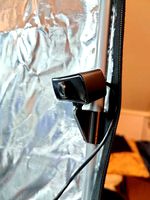
Creality ender enclosure webcam mount
...e creality enclosure. sure is better than a tripod. change it up if it helps. i printed pla with 50% infill on my dd ender 3 pro.
3d_export
free
ender 3 enclosure corners
...er corners and 4 upper corners, using 25mmx25mm angled aluminium pieces that gets covered on inside of the frame with plexiglass
3d_export
free
ender 3 3d print bed clips
...ed + normal aluminium bed frame of the creality ender 3 = 6mm (b) these clips are designed for glass plate + aluminium bed = 4mm
3d_export
$5
GRUMPY CAT
...grumpy cat 3dexport grumpy cat to print in ender ...
3d_export
$5

Logs fire
...with one multi material for corona and vray r ender. albedo, normal, uvmap, roughness format jpg 4096x4096 models:...
3d_export
$42

excavator
...is the original size. 0.12 mm printing surface creality ender5 ...
Auto
3d_export
$5

auto
...auto
3dexport
auto
3ddd
$1

auto
...auto
3ddd
max7
turbosquid
$69
AUTO
...to
turbosquid
royalty free 3d model auto for download as obj on turbosquid: 3d models for games, architecture, videos. (1453538)
3d_export
$10

Auto
...auto
3dexport
3d_export
free

auto
...auto
3dexport
3ddd
$1

Auto posters
...auto posters
3ddd
машина
auto posters
turbosquid
$50

auto
... available on turbo squid, the world's leading provider of digital 3d models for visualization, films, television, and games.
turbosquid
$28

Auto
... available on turbo squid, the world's leading provider of digital 3d models for visualization, films, television, and games.
turbosquid
$20

auto
... available on turbo squid, the world's leading provider of digital 3d models for visualization, films, television, and games.
turbosquid
$5

auto
... available on turbo squid, the world's leading provider of digital 3d models for visualization, films, television, and games.
Level
design_connected
$11

Levels
...levels
designconnected
one nordic levels computer generated 3d model. designed by form us with love.
design_connected
$7
Level
...level
designconnected
zanotta level shelves and storage computer generated 3d model. designed by arik levy.
turbosquid
$29
level
...ty free 3d model level for download as 3ds, obj, c4d, and fbx on turbosquid: 3d models for games, architecture, videos. (1272856)
turbosquid
$1
level
... available on turbo squid, the world's leading provider of digital 3d models for visualization, films, television, and games.
3d_export
$5

Mario level
...mario level
3dexport
mario level low quality for fun videos
3ddd
$1

LEVELS OF DISCOVERY
...етская мебель "levels of discovery". rab10003 princess mini rocker
кресло-качалка (мини) "принцесса навсегда"
3d_export
$19

level design
...level design
3dexport
you can use this design (level design) in your own game.
turbosquid
$60
Desert level
...squid
royalty free 3d model desert level for download as fbx on turbosquid: 3d models for games, architecture, videos. (1208131)
turbosquid
$15
Transit Level
...quid
royalty free 3d model transit level for download as max on turbosquid: 3d models for games, architecture, videos. (1158112)
turbosquid
$14

Districts Level
...id
royalty free 3d model districts level for download as max on turbosquid: 3d models for games, architecture, videos. (1408410)
Etc
3ddd
free

Oranges, mandarins etc.
...син , мандарин , фрукты
oranges, mandarins etc.
3ddd
$1

Bowls, dishes etc.
...bowls, dishes etc.
3ddd
посуда , сервиз
bowls, dishes etc. for contemporary kitchens
turbosquid
$30

theater for( cinema, collage, etc.)
...model theater for( cinema, collage, etc.) for download as fbx on turbosquid: 3d models for games, architecture, videos. (1258736)
3d_export
$40
stage light ETC 3D Model
...am shaper lighting concert music electric studio set movie lens lamp zoom reflector
stage light etc 3d model braz 7043 3dexport
3d_ocean
$8

Realistic TV/Blu-ray/DVD etc. remote
...3docean
blu-ray dvd realistic remote technology television tv
this is a model of a television, dvd, blu-ray, etc. remote control.
3d_ocean
$12

Desk accessories (pen, eraser, etc.)
...ats included: .c4d, .obj – the model contains 58530 polygons – not rigged, scene setup / lighting from the preview, are included.
3d_export
$5

kitchen assets - pots pans etc
...fferent material as they have a separate material id for the ability to personalise or have alternate lid types e.g. foggy glass.
3d_export
$15

bentley continental 2015 with all surroundings complete with lightmaterials etc
...als etc
3dexport
in the car model, each part as a separate object, which allows you to make animation or destruction in the game
3d_export
$12
set of 73 parts bolts nuts washers nails etc
...red with eevee. the wood texture is not included. all the other materials are procedural pbr configured in the native blend file.
3ddd
free
Suitcase
...suitcase 3ddd suitcase plastic suitcase for tools etc ...
10
turbosquid
$25

10
... available on turbo squid, the world's leading provider of digital 3d models for visualization, films, television, and games.
turbosquid
$10
a-10
... available on turbo squid, the world's leading provider of digital 3d models for visualization, films, television, and games.
3ddd
$1
EX 10
...ex 10
3ddd
samsung , фотоаппарат
ex 10
3ddd
$1

Bed 10
...bed 10
3ddd
постельное белье
bed 10
evermotion
$25

Scene 10 Archinteriors vol. 10
...dering design interior
take a look at textured and shadered visualization scene ready to be rendered.. evermotion 3d models shop.
3ddd
$1
Curtains 10
...curtains 10
3ddd
curtains 10
3ds max 2011,fbx + textures
polys: 100355
3ddd
free

PLANTS 10
...plants 10
3ddd
цветок , горшок
plants 10,, with 3 different color planter boxes
turbosquid
$24

Chandelier MD 89310-10+10 Osgona
... chandelier md 89310-10+10 osgona for download as max and fbx on turbosquid: 3d models for games, architecture, videos. (1218762)
design_connected
$29
Nuvola 10
...nuvola 10
designconnected
gervasoni nuvola 10 computer generated 3d model. designed by navone, paola.
design_connected
$22

Kilt 10
...kilt 10
designconnected
zanotta kilt 10 computer generated 3d model. designed by progetti, emaf.
Mounts
3d_export
free

mounting bracket
...the part of a hinge, handle or latch that mounts the hardware to a cabinet. mounting plates make it...
turbosquid
$2

MOUNTING
... available on turbo squid, the world's leading provider of digital 3d models for visualization, films, television, and games.
turbosquid
free

Mounts
... available on turbo squid, the world's leading provider of digital 3d models for visualization, films, television, and games.
turbosquid
free

Mount Fuji
...fuji
turbosquid
free 3d model mount fuji for download as obj on turbosquid: 3d models for games, architecture, videos. (1579977)
3d_export
$5

Headphone mount LR
...headphone mount lr
3dexport
headphone mount l+r
turbosquid
$39

Mount rainier
...quid
royalty free 3d model mount rainier for download as fbx on turbosquid: 3d models for games, architecture, videos. (1492586)
turbosquid
$5

pipe mounting
...quid
royalty free 3d model pipe mounting for download as obj on turbosquid: 3d models for games, architecture, videos. (1293744)
turbosquid
$3

Mounting Tires
...uid
royalty free 3d model mounting tires for download as fbx on turbosquid: 3d models for games, architecture, videos. (1708511)
3d_export
$5

Magnetic GoPro Mount
...pro mount
3dexport
cool magnetic mount for gopro. allows you to mount the camera on flat metal surfaces and get exclusive shots.
turbosquid
$5

Stone Mount
...ty free 3d model stone mount for download as ma, obj, and fbx on turbosquid: 3d models for games, architecture, videos. (1370306)
3
turbosquid
$10

Mountain Bike 3 -3 of 3
...model mountain bike 3 (#3 of 3) for download as fbx and blend on turbosquid: 3d models for games, architecture, videos. (1438752)
turbosquid
$6

Rock 3-3
...urbosquid
royalty free 3d model rock 3-3 for download as obj on turbosquid: 3d models for games, architecture, videos. (1628065)
turbosquid
$29
Books 150 pieces 3-3-3
...books 150 pieces 3-3-3 for download as max, obj, fbx, and stl on turbosquid: 3d models for games, architecture, videos. (1384033)
turbosquid
$3

Genesis 3 Clothing 3
... available on turbo squid, the world's leading provider of digital 3d models for visualization, films, television, and games.
3d_export
$5
hinge 3
...hinge 3
3dexport
hinge 3
3ddd
$1

Розетка 3
...розетка 3
3ddd
розетка
розетка 3
turbosquid
$50

is-3
... available on turbo squid, the world's leading provider of digital 3d models for visualization, films, television, and games.
turbosquid
$10

Mountain Bike 3 -2 of 3
...model mountain bike 3 (#2 of 3) for download as fbx and blend on turbosquid: 3d models for games, architecture, videos. (1438750)
turbosquid
$10
Mountain Bike 1 -3 of 3
...model mountain bike 1 (#3 of 3) for download as fbx and blend on turbosquid: 3d models for games, architecture, videos. (1438743)
3d_export
$5

3 CATS
...3 cats
3dexport
3 cats pen holder