Thingiverse
Arcade1Up - RetroPie PCB mounts
by Thingiverse
Last crawled date: 4 years, 1 month ago
The Arcade1Up home-arcade games are becoming a very popular item. At 3/4 size of the commercial cabinets, they're great for home use.
They also provide a near-perfect framework for building a RetroPie cab - using a Raspberry Pie SBC to run Games. I took my least-favorite and most control-board rich of my A1Up cabs (the Street Fighter cab) and decided to convert it to RetroPie.
There are dozens of YouTube videos on doing the work and they've helped me tremendously. I refer you to them for conversion questions.
To use the Raspberry Pie, you have to replace a couple of interfaces previously provided by the A1Up PCB: video and controls
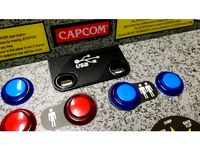
To use the existing A1UP LED screen, you need an interface between it and the Raspberry Pie HDMI output. There is an inexpensive and commonly-available controller that does this. For all the buttons and other controls, you put them on USB with a couple of interface boards.
Each of the builders attached the new PCBs to the A1Up cabinet using "double-sided sticky tape." I've used that mounting method before, but I wanted something a little less messy if I needed to move things. Plus, it's a little hair-raising trying to pry up a PCB stuck to a surface, should the need arise.
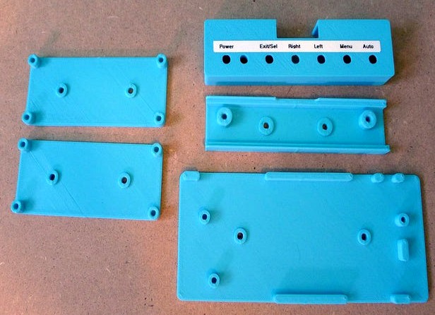
I modeled some PCB mounts as well as a cover for the video button-board. You can mount these with sticky-tape if you wish - I did for the video interface board, or you can use some short (very short) screws to attach the mounts to the cabinet surfaces.
The PCBs attach to the mounts as expected. The holes are expecting an M3 screw - I used M3-6 with a button-head. The video interface board is a little different in that it requires the grounding strap from the original A1UP PCB to be attached. I left off a post in the "upper-left" mounting position to leave room for the bolt normally used to attach the strap.
Note that all of the A1Up -> RetroPie videos say not to mount the video board on the metal back of the LED panel. Good advice if you only use sticky-tape since component leads can poke through and contact the metal back. However, to mount them anywhere else, the cables must be long enough to reach. Unfortunately the CFL power cord on my A1Up unit was so short that I couldn't mount it anywhere else without modifying the cable. With the printed PCB mount, attaching to the metal back (with sticky tape, please) doesn't present a short-circuit risk - and also provides an opportunity to put the video control button-board outside of the cabinet.
I have two version of the button-board cover - the only difference is that the connector slot on one is easier to attach without removing the cable. Also notice the two slots on the short end of the cover - this allows you to pry open the cover. I modeled it to be a bit tight.
You may notice the "museum putty" I'm using to trial-mount everything. Highly recommended.
They also provide a near-perfect framework for building a RetroPie cab - using a Raspberry Pie SBC to run Games. I took my least-favorite and most control-board rich of my A1Up cabs (the Street Fighter cab) and decided to convert it to RetroPie.
There are dozens of YouTube videos on doing the work and they've helped me tremendously. I refer you to them for conversion questions.
To use the Raspberry Pie, you have to replace a couple of interfaces previously provided by the A1Up PCB: video and controls
To use the existing A1UP LED screen, you need an interface between it and the Raspberry Pie HDMI output. There is an inexpensive and commonly-available controller that does this. For all the buttons and other controls, you put them on USB with a couple of interface boards.
Each of the builders attached the new PCBs to the A1Up cabinet using "double-sided sticky tape." I've used that mounting method before, but I wanted something a little less messy if I needed to move things. Plus, it's a little hair-raising trying to pry up a PCB stuck to a surface, should the need arise.
I modeled some PCB mounts as well as a cover for the video button-board. You can mount these with sticky-tape if you wish - I did for the video interface board, or you can use some short (very short) screws to attach the mounts to the cabinet surfaces.
The PCBs attach to the mounts as expected. The holes are expecting an M3 screw - I used M3-6 with a button-head. The video interface board is a little different in that it requires the grounding strap from the original A1UP PCB to be attached. I left off a post in the "upper-left" mounting position to leave room for the bolt normally used to attach the strap.
Note that all of the A1Up -> RetroPie videos say not to mount the video board on the metal back of the LED panel. Good advice if you only use sticky-tape since component leads can poke through and contact the metal back. However, to mount them anywhere else, the cables must be long enough to reach. Unfortunately the CFL power cord on my A1Up unit was so short that I couldn't mount it anywhere else without modifying the cable. With the printed PCB mount, attaching to the metal back (with sticky tape, please) doesn't present a short-circuit risk - and also provides an opportunity to put the video control button-board outside of the cabinet.
I have two version of the button-board cover - the only difference is that the connector slot on one is easier to attach without removing the cable. Also notice the two slots on the short end of the cover - this allows you to pry open the cover. I modeled it to be a bit tight.
You may notice the "museum putty" I'm using to trial-mount everything. Highly recommended.
Similar models
thingiverse
free

Keyboard holder
...d holder
thingiverse
simple keyboard holder i made for my arcade1up cab running retropie. used double side tape to hold it down.
thingiverse
free

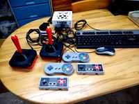
A1Up RetroPie front control panel
...you, too, if you're going to be building a hardware-similar front panel, but a step-by-step for the complete build...
thingiverse
free

NCE BD20 mount
...9;ve uploaded a fusion 360 archive file so you can change the "board" parameters to match any mountless board you have.
thingiverse
free

Raspi FLIRC case hanger
...er, so if you decide to screw-mount it, you'll need screws with a low-profile head so they don't interfere with the case.
thingiverse
free
Arcade1Up USB Button Plate (Arcade 1Up)
...the holes, covers up the text on the control panel, and features a usb logo. i used a silver sharpie marker to color in the logo.
thingiverse
free

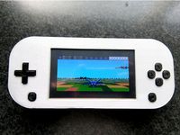
RetroPie Handheld by craiglitwiller
...also testing a different battery and will update the list if it works out better. the current battery doesn't last very long.
thingiverse
free

Mount for Raspberry Pi (Arcade1up modding) by Tinkering_On_Steroids
...mount for raspberry pi (arcade1up modding) by tinkering_on_steroids
thingiverse
mount for raspberry pi (arcade1up modding)
thingiverse
free

Arcade1up Monitor Bracket
...uot;) for mounting monitor inside arcade1up cab.
make shure to use non brittal material for 3d printing.
100% infill recommended.
thingiverse
free
Spot Micro Plain Plate and Rpi and Servo Board Mounts by mike4192
... raspberry pi 3 and a pca9685 servo control board. small wood screws can be used to securely attach those boards to these plates.
thingiverse
free

Makerbot Replicator 2 corner mount for Raspberry Pi Camera by ceypher
...ith the entire field of view
prefer plastics screws for mounting to avoid short circuits on the pcb
attach with double sided tape
Arcade1Up
thingiverse
free
Arcade1up Monitor Bracket
...uot;) for mounting monitor inside arcade1up cab.
make shure to use non brittal material for 3d printing.
100% infill recommended.
thingiverse
free
Mount for Raspberry Pi (Arcade1up modding) by Tinkering_On_Steroids
...mount for raspberry pi (arcade1up modding) by tinkering_on_steroids
thingiverse
mount for raspberry pi (arcade1up modding)
thingiverse
free

Arcade1Up PC Power Button
...r switch with a 16mm pc power button.
button i used -https://www.amazon.com/knacro-chassis-switch-computer-restart/dp/b01n6ksuzl/
thingiverse
free

Mount for LCD driver board (Arcade1up modding) by Tinkering_On_Steroids
...nt for lcd driver board (arcade1up modding) by tinkering_on_steroids
thingiverse
mount for lcd driver board (arcade1up modding).
thingiverse
free

Arcade1Up SwitchBracket_v2 for Monoprice Select Mini by Hilux74
... the edges of bumbumbum's arcade1up switchbracket v2 so it will fit the print bed area of the monoprice select mini printer
thingiverse
free

Happ Joystick Alignment Tool. Arcade1Up
.... tool works perfectly and cuts out all the time of aligning and realigning, then aligning some more in order to get it perfect.
thingiverse
free
ARCADE1UP SPACER
...hen youi add the plexiglass control panel overlay. this prevents your plexiglass cover from cracking when you tighten the screws.
thingiverse
free

arcade1up marquee panel mounts by arcadeforever
... by arcadeforever
thingiverse
these are mounts for the amazon or aliexpress lcd panel that most people use for a marquee.
enjoy!
thingiverse
free
Arcade1Up USB Button Plate (Arcade 1Up)
...the holes, covers up the text on the control panel, and features a usb logo. i used a silver sharpie marker to color in the logo.
thingiverse
free

Arcade1up 14.9 Inch Marquee Frame by topperge
... a large printer where i could pre-assemble the 3 parts of the frame and just print it once and save some screws, glue, and pins.
Retropie
thingiverse
free

RetroPi Logo by AwesomeA
...retropi logo by awesomea
thingiverse
retropi logo
thingiverse
free

My RetroPie
...my retropie
thingiverse
this is a test.
thingiverse
free

RetroPie Box by StreetMaker
... cabinet? its got to be portable! and better cost less than $50.
well here is my version of an all inclusive box for the retropie
thingiverse
free
RetroPie Handheld by Cees_Meijer
... 3 a+ running retropie.
check the details and build instruction on hackaday:
https://hackaday.io/project/176661-retropie-handheld
thingiverse
free
Retropie Game Station 2 by paulvanviegen
...rse
with this design you can make a retropie game station. you need a raspberry pi with retropie installed and an 7 inch screen.
thingiverse
free

Retropie Game Station by paulvanviegen
...led and an 7 inch screen. the controllers can be stored on the front of the station. a speaker could be placed inside the sftion.
thingiverse
free

RetroPi TV front panel by BC_Jeffro
... bc_jeffro
thingiverse
front cover for retropi tv
by joo, that was published feb 4, 2015https://www.thingiverse.com/thing:666802
thingiverse
free
Retropie Gaming Station by Snille
...l to come together... this is just the 3d-printable box. :)
you can make the box your own, download and edit the sketchup file.
thingiverse
free

Retropie Arcade Stick by gerk20
... printer!
buttons and joystick - https://www.amazon.com/gp/product/b01m2x88qp/ref=ppx_yo_dt_b_search_asin_title?ie=utf8&psc=1
thingiverse
free

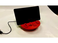
Retropie drinkcoaster
... (100 by 100 by 5 mm), to fit in my coasterholder:
https://www.thingiverse.com/thing:3130397
made with love by:
raimon of idealab
Pcb
3ddd
$1
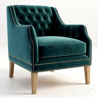
GRAMERCY HOME - CARMELA ARMCHAIR 602.023-PCB
...gramercy home - carmela armchair 602.023-pcb
3ddd
gramercy home
gramercy home
carmela armchair
602.023-pcb
www.gramercy-home.ru
3d_export
$150
auto pcb board loder inspection machine
...auto pcb board loder inspection machine
3dexport
auto pcb board loder & inspection machine --> only step file
3d_export
$7
turning mechanism drawing pcb board turnover machine
...turning mechanism drawing pcb board turnover machine
3dexport
turning mechanism drawing pcb board turnover machine
turbosquid
$9

Stereo Jack 3.5mm for soldering to a PCB
... available on turbo squid, the world's leading provider of digital 3d models for visualization, films, television, and games.
3d_export
$5
LED Right Angled PCB Mounting
...m led. step and igus files. multiple led colors: blue, purple, red, green, and yellow. dimensions case w 4,5mm , h 7,3mm l 6,4mm.
3d_export
$20
automatic pcb loading and unloading dispensing test automatic line
...ment structure is very complex. it is a very practical equipment for smt industry. the equipment is mature application equipment.
3d_export
$18
an automatic line for fct function test of pcb
... drawings are downloaded, you can directly watch and edit the contents. welcome to download and learn from your favorite friends.
3d_export
$5
USB Micro B connector
...step and igus for 3d import into ecad tools, pcb footprints. added also a altium designer pcb component library...
3d_export
$15
plastic housing with dewalt battery holder
...case measures 155x106x60. inside the case there are two pcb of 130x98 and 98x42...
3d_export
$7
automatic packing line - packing sorting and stacking equipment line
...sorting and stacking equipment line 3dexport automatic packaging line<br>1. pcb board is manually placed from the placement position and...
Mounts
3d_export
free

mounting bracket
...the part of a hinge, handle or latch that mounts the hardware to a cabinet. mounting plates make it...
turbosquid
$2

MOUNTING
... available on turbo squid, the world's leading provider of digital 3d models for visualization, films, television, and games.
turbosquid
free

Mounts
... available on turbo squid, the world's leading provider of digital 3d models for visualization, films, television, and games.
turbosquid
free

Mount Fuji
...fuji
turbosquid
free 3d model mount fuji for download as obj on turbosquid: 3d models for games, architecture, videos. (1579977)
3d_export
$5

Headphone mount LR
...headphone mount lr
3dexport
headphone mount l+r
turbosquid
$39

Mount rainier
...quid
royalty free 3d model mount rainier for download as fbx on turbosquid: 3d models for games, architecture, videos. (1492586)
turbosquid
$5

pipe mounting
...quid
royalty free 3d model pipe mounting for download as obj on turbosquid: 3d models for games, architecture, videos. (1293744)
turbosquid
$3

Mounting Tires
...uid
royalty free 3d model mounting tires for download as fbx on turbosquid: 3d models for games, architecture, videos. (1708511)
3d_export
$5

Magnetic GoPro Mount
...pro mount
3dexport
cool magnetic mount for gopro. allows you to mount the camera on flat metal surfaces and get exclusive shots.
turbosquid
$5

Stone Mount
...ty free 3d model stone mount for download as ma, obj, and fbx on turbosquid: 3d models for games, architecture, videos. (1370306)