Thingiverse
Anycubic i3 Mega (Mega-S) case for USB-step-down-converter by henniero
by Thingiverse
Last crawled date: 4 years, 4 months ago
English version: (german version below)
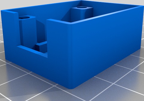
I designed this case for an USB stepdown-converter that fits perfectly onto the case of my Anycubic i3 Mega-S Printer. (i3 Mega should also work fine).
The mounting holes and the recess for feeding in the wires are matched up with the pattern-distance of the Mega (Mega-S) case design.
Printing
Parts to print:
1x 01_Lid
1x 02_Main (_self-tapping OR _through-hole OR _M3inserts)
01_Lid (It will fit onto all the variants of the main case)
Orientation already set correctly in stl-file
0,4mm Nozzle
Resolution: 0,2mm
Infill: 20% (Pattern doesn't matter)
Support: Optional (touching Buildplate) for the recessed screw holes
02_Main(_self-tapping)(_through-hole)(_M3inserts)
Orientation already set correctly in stl-file
0,4mm Nozzle
Resolution: 0,2mm
Infill: 20% (Pattern doesn't matter)
Support: no
BOM
1 Pcs. 2A(3A) USB Stepdown converter 12-24V to 5V (27x15mm)
https://www.ebay.de/itm/USB-Step-Down-DC-DC-Spannungswandler-6-24V-zu-5V-3A-Arduino-Spannungsregler/153871569979?\_trkparms=aid%3D111001%26algo%3DREC.SEED%26ao%3D1%26asc%3D20170511121231%26meid%3Dbb20643ce6d942cd9ded58eaccf4a2fc%26pid%3D100675%26rk%3D1%26rkt%3D15%26mehot%3Dpp%26sd%3D153871569979%26itm%3D153871569979%26pmt%3D1%26noa%3D1%26pg%3D2380057&\_trksid=p2380057.c100675.m4236&\_trkparms=pageci%3Ad96f4b14-83de-11eb-aae8-3223fd6276b4%7Cparentrq%3A2aece65c1780a4d3624ac984ffd2b232%7Ciid%3A1
https://www.amazon.de/ANGEEK-st%C3%BCck-Charger-Supply-Module/dp/B07Q7TTD6C/ref=sr\_1\_5?\_\_mk\_de\_DE=%C3%85M%C3%85%C5%BD%C3%95%C3%91&dchild=1&keywords=USB+Step+Down+DC-DC+Spannungswandler+6-24V+zu+5V&qid=1615627966&sr=8-5
https://de.aliexpress.com/item/32778834699.html?spm=a2g0o.productlist.0.0.7bea5548LMwGR8&algo\_pvid=c35477e7-8388-447f-b394-bbbc1cb8909b&algo\_expid=c35477e7-8388-447f-b394-bbbc1cb8909b-45&btsid=2100bb5116156280880794969ea30b&ws\_ab\_test=searchweb0\_0,searchweb201602\_,searchweb201603\_
Variant: 02_Main_self-tapping
8 Pcs. M3x6 or M3x8
4 Pcs. M3 Washers
Variant: 02_Main_through-hole
4 Pcs. M3x20
4 Pcs. M3 Washers
4 Pcs. M3 Nuts
Variant: 02_Main_M3inserts (only as Example)
8 Pcs. M3x6 or M3x8
8 Pcs. M3 Inserts (e.g. Ruthex)
4 Pcs. M3 Washers
Assembly
I designed this to be fitted on the left side of the printer (power-supply side). It can be fitted on the right side (mainboard side), but here you can only mount the case to the printer case with two screws.
Variant: 02_Main_self-tapping
After Printing I recommend to tap in the screws once to make assembly in the printer case easier
When you choose the position on the left like I did, you have to loosen up the printer power-supply and move it out of the way a bit for installation.
From the inside of the printer use 4 screws and 4 washers to attach the case to the printer.
Feed the wires for V+ and GND through the recess into the case.
Solder the wires (make sure for correct polarity) to the pcb of the stepdown converter. I just soldered the wires on the top of the pcb to the pads.
Snap the pcb into place in the case
Attach the lid with the remaining 4 screws
Variant: 02_Main_through-hole
Installation is pretty much the same. Here you have to put everything together and then you have to attach the case and the lid (sandwich style) to the printer case with 4 M3x20 screws and secure it with 4 washers and 4 nuts on the inside of the printer.
Variant: 02_Main_M3inserts
Installation like self-tapping variant
BUT: I WILL MARK THIS AS AN EXAMPLE ONLY! The tolerances for M3inserts are below the specs in this case. It works fine for me, but I don't guarantee it.
WARNING/DISCLAIMER
Unplug your printer before opening it! Working on electric/electronic devices is only for authorized persons! If you do so, you do at your own risk! I will take no responsibility for any damage.
When you use a free tap on your printer power-supply you MUST install an inline fuse. A small gauge wire that is used for supplying the step-down converter is not rated for the 30A the power-supply can deliver. If a shortage occurs the over-current protection of the power-supply might not trip. This is a serious fire-hazard. An inline-fuse (e.g. 4A) is mandatory.
Deutsche Version:
Ich habe dieses kleine Gehäuse für einen USB-step-down Wandler entwickelt, das perfekt an das Gehäuse meines Anycubic i3 Mega-S-Druckers passt. (Für den i3 Mega sollte es natürlich auch funktionieren).
Die Befestigungslöcher und die Aussparung zum Einführen der Leitungen sind auf den Musterabstand des Mega (Mega-S) - Gehäusedesigns abgestimmt.
Drucken
Zu druckende Teile:
1x 01_Lid
1x 02_Main (_self-tapping ODER _through-hole ODER _M3inserts)
01_Lid (Der Deckel passt auf alle Varianten des Gehäuses)
Ausrichtung bereits korrekt in der STL-Datei
0,4mm Nozzle
Resolution: 0,2mm
Infill: 20% (Muster nach belieben)
Support: Optional (touching Buildplate) für die Schraubenkopfvertiefungen
02_Main(_self-tapping)(_through-hole)(_M3inserts)
Ausrichtung bereits korrekt in der STL-Datei
0,4mm Nozzle
Resolution: 0,2mm
Infill: 20% (Muster nach belieben)
Support: Nein
Stückliste
1 Stk. 2A(3A) USB Stepdown converter 6-24V to 5V (27x15mm)
Drei Bezugsquellen als Beispiel:
https://www.ebay.de/itm/USB-Step-Down-DC-DC-Spannungswandler-6-24V-zu-5V-3A-Arduino-Spannungsregler/153871569979?\_trkparms=aid%3D111001%26algo%3DREC.SEED%26ao%3D1%26asc%3D20170511121231%26meid%3Dbb20643ce6d942cd9ded58eaccf4a2fc%26pid%3D100675%26rk%3D1%26rkt%3D15%26mehot%3Dpp%26sd%3D153871569979%26itm%3D153871569979%26pmt%3D1%26noa%3D1%26pg%3D2380057&\_trksid=p2380057.c100675.m4236&\_trkparms=pageci%3Ad96f4b14-83de-11eb-aae8-3223fd6276b4%7Cparentrq%3A2aece65c1780a4d3624ac984ffd2b232%7Ciid%3A1
https://www.amazon.de/ANGEEK-st%C3%BCck-Charger-Supply-Module/dp/B07Q7TTD6C/ref=sr\_1\_5?\_\_mk\_de\_DE=%C3%85M%C3%85%C5%BD%C3%95%C3%91&dchild=1&keywords=USB+Step+Down+DC-DC+Spannungswandler+6-24V+zu+5V&qid=1615627966&sr=8-5
https://de.aliexpress.com/item/32778834699.html?spm=a2g0o.productlist.0.0.7bea5548LMwGR8&algo\_pvid=c35477e7-8388-447f-b394-bbbc1cb8909b&algo\_expid=c35477e7-8388-447f-b394-bbbc1cb8909b-45&btsid=2100bb5116156280880794969ea30b&ws\_ab\_test=searchweb0\_0,searchweb201602\_,searchweb201603\_
Variante: 02_Main_self-tapping
8 Stk. M3x6 oder M3x8
4 Stk. M3 Unterlegscheiben
Variante: 02_Main_through-hole
4 Stk. M3x20
4 Stk. M3 Unterlegscheiben
4 Stk. M3 Muttern
Variante: 02_Main_M3inserts (nur Beispielhaft!)
8 Stk. M3x6 oder M3x8
8 Stk. M3 Gewindeeinsätze (z.B. Ruthex)
4 Stk. M3 Unterlegscheiben
Montage
Ich habe das Gehäuse so konzipiert, dass es auf der linken Seite des Druckers (Netzteilseite) angebracht wird. Es kann auch auf der rechten Seite (Mainboard-Seite) montiert werden, allerdings kann das Gehäuse hier nur mit zwei Schrauben Drucker befestigt werden.
Variante: 02_Main_self-tapping
Nach dem Drucken empfehle ich, die Schrauben einmal einzuschrauben, um die Montage im Druckergehäuse zu erleichtern.
Wenn du wie ich die Position links auswählst, muss das Netzteil des Druckers gelöst werden um es für die Installation des Gehäuses ein wenig zur Seite zu schieben.
Befestige das Gehäuse von der Innenseite des Druckers mit 4 Schrauben und 4 Unterlegscheiben am Drucker.
Führe die Leitungen für V + und GND durch die Aussparung in das Gehäuse.
Löte die Leitungen (achte auf die richtige Polarität!) auf die Platine des Step-Down-Wandlers. Ich habe die Leitungen von oben auf der Platine auf den Pads verlötet.
Raste die Platine in das Gehäuse ein
Befestige den Deckel mit den restlichen 4 Schrauben
Variante: 02_Main_through-hole
Die Installation ist ziemlich gleich. Hier muss man erst alles zusammensetzen und dann das Gehäuse und den Deckel (Sandwich-Stil) mit 4 M3x20-Schrauben am Druckergehäuse befestigen und mit 4 Unterlegscheiben und 4 Muttern an der Innenseite des Druckers befestigen.
Variante: 02_Main_M3inserts
Installation wie die selbstschneidende Variante
ACHTUNG: Ich werde dies nur als Beispiel markieren! Die Toleranzen für M3-Einsätze liegen in diesem Fall außerhalb den Spezifikationen. Es funktioniert bei mir gut aber ich garantiere nicht für den Erfolg.
WARNUNG / HAFTUNGSAUSSCHLUSS
Ziehe den Stecker aus der Steckdose, bevor du den Drucker öffnest! Arbeiten an elektrischen / elektronischen Geräten ist nur etwas für befugte Personen! Wenn du es trotzdem machst geschieht dies auf eigenes Risiko! Ich übernehme keine Verantwortung für Schäden.
Wenn ein freier Abgang an der Stromversorgung des Druckers verwendet wird, MUSS eine Inline-Sicherung installiert werden. Eine Leitung mit kleinem Querschnitt, welche zur Versorgung des Step-Down-Wandlers verwendet wird, ist nicht für die 30 A ausgelegt. Wenn ein Kurzschluss auftritt, wird der Überstromschutz des Netzteils möglicherweise nicht ansprechen. Dies ist eine ernsthafte Brandgefahr! Eine Inline-Sicherung (z.B.4A) ist obligatorisch.
I designed this case for an USB stepdown-converter that fits perfectly onto the case of my Anycubic i3 Mega-S Printer. (i3 Mega should also work fine).
The mounting holes and the recess for feeding in the wires are matched up with the pattern-distance of the Mega (Mega-S) case design.
Printing
Parts to print:
1x 01_Lid
1x 02_Main (_self-tapping OR _through-hole OR _M3inserts)
01_Lid (It will fit onto all the variants of the main case)
Orientation already set correctly in stl-file
0,4mm Nozzle
Resolution: 0,2mm
Infill: 20% (Pattern doesn't matter)
Support: Optional (touching Buildplate) for the recessed screw holes
02_Main(_self-tapping)(_through-hole)(_M3inserts)
Orientation already set correctly in stl-file
0,4mm Nozzle
Resolution: 0,2mm
Infill: 20% (Pattern doesn't matter)
Support: no
BOM
1 Pcs. 2A(3A) USB Stepdown converter 12-24V to 5V (27x15mm)
https://www.ebay.de/itm/USB-Step-Down-DC-DC-Spannungswandler-6-24V-zu-5V-3A-Arduino-Spannungsregler/153871569979?\_trkparms=aid%3D111001%26algo%3DREC.SEED%26ao%3D1%26asc%3D20170511121231%26meid%3Dbb20643ce6d942cd9ded58eaccf4a2fc%26pid%3D100675%26rk%3D1%26rkt%3D15%26mehot%3Dpp%26sd%3D153871569979%26itm%3D153871569979%26pmt%3D1%26noa%3D1%26pg%3D2380057&\_trksid=p2380057.c100675.m4236&\_trkparms=pageci%3Ad96f4b14-83de-11eb-aae8-3223fd6276b4%7Cparentrq%3A2aece65c1780a4d3624ac984ffd2b232%7Ciid%3A1
https://www.amazon.de/ANGEEK-st%C3%BCck-Charger-Supply-Module/dp/B07Q7TTD6C/ref=sr\_1\_5?\_\_mk\_de\_DE=%C3%85M%C3%85%C5%BD%C3%95%C3%91&dchild=1&keywords=USB+Step+Down+DC-DC+Spannungswandler+6-24V+zu+5V&qid=1615627966&sr=8-5
https://de.aliexpress.com/item/32778834699.html?spm=a2g0o.productlist.0.0.7bea5548LMwGR8&algo\_pvid=c35477e7-8388-447f-b394-bbbc1cb8909b&algo\_expid=c35477e7-8388-447f-b394-bbbc1cb8909b-45&btsid=2100bb5116156280880794969ea30b&ws\_ab\_test=searchweb0\_0,searchweb201602\_,searchweb201603\_
Variant: 02_Main_self-tapping
8 Pcs. M3x6 or M3x8
4 Pcs. M3 Washers
Variant: 02_Main_through-hole
4 Pcs. M3x20
4 Pcs. M3 Washers
4 Pcs. M3 Nuts
Variant: 02_Main_M3inserts (only as Example)
8 Pcs. M3x6 or M3x8
8 Pcs. M3 Inserts (e.g. Ruthex)
4 Pcs. M3 Washers
Assembly
I designed this to be fitted on the left side of the printer (power-supply side). It can be fitted on the right side (mainboard side), but here you can only mount the case to the printer case with two screws.
Variant: 02_Main_self-tapping
After Printing I recommend to tap in the screws once to make assembly in the printer case easier
When you choose the position on the left like I did, you have to loosen up the printer power-supply and move it out of the way a bit for installation.
From the inside of the printer use 4 screws and 4 washers to attach the case to the printer.
Feed the wires for V+ and GND through the recess into the case.
Solder the wires (make sure for correct polarity) to the pcb of the stepdown converter. I just soldered the wires on the top of the pcb to the pads.
Snap the pcb into place in the case
Attach the lid with the remaining 4 screws
Variant: 02_Main_through-hole
Installation is pretty much the same. Here you have to put everything together and then you have to attach the case and the lid (sandwich style) to the printer case with 4 M3x20 screws and secure it with 4 washers and 4 nuts on the inside of the printer.
Variant: 02_Main_M3inserts
Installation like self-tapping variant
BUT: I WILL MARK THIS AS AN EXAMPLE ONLY! The tolerances for M3inserts are below the specs in this case. It works fine for me, but I don't guarantee it.
WARNING/DISCLAIMER
Unplug your printer before opening it! Working on electric/electronic devices is only for authorized persons! If you do so, you do at your own risk! I will take no responsibility for any damage.
When you use a free tap on your printer power-supply you MUST install an inline fuse. A small gauge wire that is used for supplying the step-down converter is not rated for the 30A the power-supply can deliver. If a shortage occurs the over-current protection of the power-supply might not trip. This is a serious fire-hazard. An inline-fuse (e.g. 4A) is mandatory.
Deutsche Version:
Ich habe dieses kleine Gehäuse für einen USB-step-down Wandler entwickelt, das perfekt an das Gehäuse meines Anycubic i3 Mega-S-Druckers passt. (Für den i3 Mega sollte es natürlich auch funktionieren).
Die Befestigungslöcher und die Aussparung zum Einführen der Leitungen sind auf den Musterabstand des Mega (Mega-S) - Gehäusedesigns abgestimmt.
Zu druckende Teile:
1x 01_Lid
1x 02_Main (_self-tapping ODER _through-hole ODER _M3inserts)
01_Lid (Der Deckel passt auf alle Varianten des Gehäuses)
Ausrichtung bereits korrekt in der STL-Datei
0,4mm Nozzle
Resolution: 0,2mm
Infill: 20% (Muster nach belieben)
Support: Optional (touching Buildplate) für die Schraubenkopfvertiefungen
02_Main(_self-tapping)(_through-hole)(_M3inserts)
Ausrichtung bereits korrekt in der STL-Datei
0,4mm Nozzle
Resolution: 0,2mm
Infill: 20% (Muster nach belieben)
Support: Nein
Stückliste
1 Stk. 2A(3A) USB Stepdown converter 6-24V to 5V (27x15mm)
Drei Bezugsquellen als Beispiel:
https://www.ebay.de/itm/USB-Step-Down-DC-DC-Spannungswandler-6-24V-zu-5V-3A-Arduino-Spannungsregler/153871569979?\_trkparms=aid%3D111001%26algo%3DREC.SEED%26ao%3D1%26asc%3D20170511121231%26meid%3Dbb20643ce6d942cd9ded58eaccf4a2fc%26pid%3D100675%26rk%3D1%26rkt%3D15%26mehot%3Dpp%26sd%3D153871569979%26itm%3D153871569979%26pmt%3D1%26noa%3D1%26pg%3D2380057&\_trksid=p2380057.c100675.m4236&\_trkparms=pageci%3Ad96f4b14-83de-11eb-aae8-3223fd6276b4%7Cparentrq%3A2aece65c1780a4d3624ac984ffd2b232%7Ciid%3A1
https://www.amazon.de/ANGEEK-st%C3%BCck-Charger-Supply-Module/dp/B07Q7TTD6C/ref=sr\_1\_5?\_\_mk\_de\_DE=%C3%85M%C3%85%C5%BD%C3%95%C3%91&dchild=1&keywords=USB+Step+Down+DC-DC+Spannungswandler+6-24V+zu+5V&qid=1615627966&sr=8-5
https://de.aliexpress.com/item/32778834699.html?spm=a2g0o.productlist.0.0.7bea5548LMwGR8&algo\_pvid=c35477e7-8388-447f-b394-bbbc1cb8909b&algo\_expid=c35477e7-8388-447f-b394-bbbc1cb8909b-45&btsid=2100bb5116156280880794969ea30b&ws\_ab\_test=searchweb0\_0,searchweb201602\_,searchweb201603\_
Variante: 02_Main_self-tapping
8 Stk. M3x6 oder M3x8
4 Stk. M3 Unterlegscheiben
Variante: 02_Main_through-hole
4 Stk. M3x20
4 Stk. M3 Unterlegscheiben
4 Stk. M3 Muttern
Variante: 02_Main_M3inserts (nur Beispielhaft!)
8 Stk. M3x6 oder M3x8
8 Stk. M3 Gewindeeinsätze (z.B. Ruthex)
4 Stk. M3 Unterlegscheiben
Montage
Ich habe das Gehäuse so konzipiert, dass es auf der linken Seite des Druckers (Netzteilseite) angebracht wird. Es kann auch auf der rechten Seite (Mainboard-Seite) montiert werden, allerdings kann das Gehäuse hier nur mit zwei Schrauben Drucker befestigt werden.
Variante: 02_Main_self-tapping
Nach dem Drucken empfehle ich, die Schrauben einmal einzuschrauben, um die Montage im Druckergehäuse zu erleichtern.
Wenn du wie ich die Position links auswählst, muss das Netzteil des Druckers gelöst werden um es für die Installation des Gehäuses ein wenig zur Seite zu schieben.
Befestige das Gehäuse von der Innenseite des Druckers mit 4 Schrauben und 4 Unterlegscheiben am Drucker.
Führe die Leitungen für V + und GND durch die Aussparung in das Gehäuse.
Löte die Leitungen (achte auf die richtige Polarität!) auf die Platine des Step-Down-Wandlers. Ich habe die Leitungen von oben auf der Platine auf den Pads verlötet.
Raste die Platine in das Gehäuse ein
Befestige den Deckel mit den restlichen 4 Schrauben
Variante: 02_Main_through-hole
Die Installation ist ziemlich gleich. Hier muss man erst alles zusammensetzen und dann das Gehäuse und den Deckel (Sandwich-Stil) mit 4 M3x20-Schrauben am Druckergehäuse befestigen und mit 4 Unterlegscheiben und 4 Muttern an der Innenseite des Druckers befestigen.
Variante: 02_Main_M3inserts
Installation wie die selbstschneidende Variante
ACHTUNG: Ich werde dies nur als Beispiel markieren! Die Toleranzen für M3-Einsätze liegen in diesem Fall außerhalb den Spezifikationen. Es funktioniert bei mir gut aber ich garantiere nicht für den Erfolg.
WARNUNG / HAFTUNGSAUSSCHLUSS
Ziehe den Stecker aus der Steckdose, bevor du den Drucker öffnest! Arbeiten an elektrischen / elektronischen Geräten ist nur etwas für befugte Personen! Wenn du es trotzdem machst geschieht dies auf eigenes Risiko! Ich übernehme keine Verantwortung für Schäden.
Wenn ein freier Abgang an der Stromversorgung des Druckers verwendet wird, MUSS eine Inline-Sicherung installiert werden. Eine Leitung mit kleinem Querschnitt, welche zur Versorgung des Step-Down-Wandlers verwendet wird, ist nicht für die 30 A ausgelegt. Wenn ein Kurzschluss auftritt, wird der Überstromschutz des Netzteils möglicherweise nicht ansprechen. Dies ist eine ernsthafte Brandgefahr! Eine Inline-Sicherung (z.B.4A) ist obligatorisch.