Thingiverse
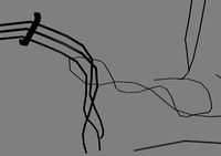
Anycubic 4max Motherboard wiring diagram by matflat
by Thingiverse
Last crawled date: 3 years, 1 month ago
You dont need Dummy.stl its a placeholder
########################## Saftey Note! ##########################
!!!Warning!!!
Keep in mind that 230 / 110 Volts is a hazard for life! Only open the elecronic box if you know what you are doing! This voltage is very dangerous! You open the box at your own risk! I do not guarantee that this plan is correct!
########################## Description: ##########################
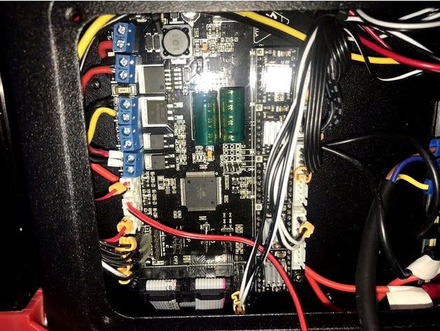
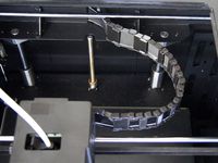
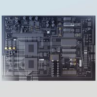
This plan has nothing to do with an electical circuit plan, its just for understanding whats going on in the electronic compartment.
I took a Multimeter and messuared out the most important connections.
@ 25 Degrees C the Thermistors ( Bed and cartridge heater sensor) should have about 103 Ohms.
The heated bed should have about one Ohm resistance. The cartridge heater about 3.5 Ohms.
F stands for Filamentsensor.
########################## Important! ##########################
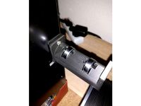
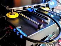
As you can see on the picture,I tried to put ferrules on the wires but on the power supply cable for the motherboard it didn't worked, because the ferrules would be to big for the screw terminal. Lead on the wires and to put it in the terminal is no good idea, because over time it would do the so called "cold flow" The wire becomes loose and could get a potential fire hazzard! A better and safe way would be to solder the wires direct on the board. I would also recommend to use a mosfet to be safe.
Because we put our printers on our own together we have to take care about fire protection. You wont get a penny from anycubic if your home burns down!
I hope this drawing can be useful for you!
Remember! 3d printers are a fire hazard!! Do something against it...
########################## Saftey Note! ##########################
!!!Warning!!!
Keep in mind that 230 / 110 Volts is a hazard for life! Only open the elecronic box if you know what you are doing! This voltage is very dangerous! You open the box at your own risk! I do not guarantee that this plan is correct!
########################## Description: ##########################
This plan has nothing to do with an electical circuit plan, its just for understanding whats going on in the electronic compartment.
I took a Multimeter and messuared out the most important connections.
@ 25 Degrees C the Thermistors ( Bed and cartridge heater sensor) should have about 103 Ohms.
The heated bed should have about one Ohm resistance. The cartridge heater about 3.5 Ohms.
F stands for Filamentsensor.
########################## Important! ##########################
As you can see on the picture,I tried to put ferrules on the wires but on the power supply cable for the motherboard it didn't worked, because the ferrules would be to big for the screw terminal. Lead on the wires and to put it in the terminal is no good idea, because over time it would do the so called "cold flow" The wire becomes loose and could get a potential fire hazzard! A better and safe way would be to solder the wires direct on the board. I would also recommend to use a mosfet to be safe.
Because we put our printers on our own together we have to take care about fire protection. You wont get a penny from anycubic if your home burns down!
I hope this drawing can be useful for you!
Remember! 3d printers are a fire hazard!! Do something against it...
Similar models
thingiverse
free
Wire Ferrule Magazine Autoloader by robssm
...r it.
this should have been invented about 60 years ago, but, we do what we can. modify to your hearts content and happy wiring!
thingiverse
free

Anycubic kossel LCD screen stand by Redbrumbler
...may put your own name on there.
have not been able to print it yet dues to my printer not coöperating, so print at your own risk!
thingiverse
free
Wire Strain Relief for Anycubic Kossel XL Print Head by Kiolia
...be sure i had enough threads engaged since on the anycubic these screws are what hold the hotend into the overall head assembly.
thingiverse
free

Mock 3D Printer by sherrijoe
...3d printers what they actually look like.
on the printer platform is the first design that i have ever created with a 3d printer.
thingiverse
free

Anet A8 / Anycubic prusa i3 Bed level test by gsiak96
.../ anycubic prusa i3 bed level test by gsiak96
thingiverse
have fun with it!
do you like it?
i would be very pleased about a tip!
thingiverse
free

Pen and Cartridge Holder by Indycross
...ery clogged. you do have to use supports because i made the inside hollow (with a solid base). they should connect to each other?
thingiverse
free

Bibo wire grommet by Randyrw
...zer ready. with it the grommets can be adjusted for different printers.
print settings .2, infill should not matter, no supports.
thingiverse
free

LED Light strips for FlashForge Creator Pro by aesdaile
... of wiring up circuits like this. if you don't know what you are doing you will damage your printer, motherboard or yourself.
thingiverse
free

Stand for Guardian III E-Pipe by hamop
...cause of it's shape. so, i fired up the printer and made a stand for it to always have it nicely displayed and safely stored.
3dwarehouse
free

Post Terminals
...post terminals
3dwarehouse
cartridge heater with post terminals #cartridge_heater #marathon_heater #post_terminals
Matflat
thingiverse
free

5 Day + Weekend Pillbox / Tabletten by matflat
...3x1 inch
print it with no support
0,2 layer height
50mm/s print speed
160mm/s travel speed
pls let me know if you printed it too!
thingiverse
free
Anycubic 4max Dustcover 100% printable by matflat
...ine.
print the handle from the side.
at least glue everything together. (do not use heatglue)
feel free to modify it as you like
thingiverse
free

USB in a CD / DVD Case, <<USB in a Box>> by matflat
... because there are big differences on the market.
a nice idea would also be to glue it with a two sided gluetape.
happy printing!
4Max
thingiverse
free
4Max Spoolholder by layos82
...4max spoolholder by layos82
thingiverse
this is a remix of https://www.thingiverse.com/thing:2909802 for the anycubic 4max
thingiverse
free
4MAX - BLTouch Holder
...4max - bltouch holder
thingiverse
-
thingiverse
free

Anycubic 4MAX LCD Cover by HuGhost
...anycubic 4max lcd cover by hughost
thingiverse
anycubic 4max lcd cover
clean and 4max logo better fit
thingiverse
free
Knob for Anycubic 4MAX by aziodale
...ob for anycubic 4max by aziodale
thingiverse
bigger knob for anycubic 4max, facilitates bed adjustment by requiring less force.
thingiverse
free
4Max Pro Vibration Damper
...pro vibration damper
thingiverse
a vibration damper made for the anycubic 4max pro. also reduces the jerk noises of the printer.
thingiverse
free
Anycubic 4Max Pro Cable Chain
...anycubic 4max pro cable chain
thingiverse
cable chain for anycubic 4max pro
thingiverse
free

Camera mount C270 on 4Max by Kimmeke
...camera mount c270 on 4max by kimmeke
thingiverse
c270 logitech mount for 4max anycubic
thingiverse
free
4Max Pro Filament Miniature Cleaner
...4max pro filament miniature cleaner
thingiverse
a miniature of the anycubic 4max pro as a filament cleaner
thingiverse
free

4MAX LED Holder by runUNDfun
...d holder by runundfun
thingiverse
4max/fourmax led holder.
inserted two 2mm holes to fixed the led stripe with a small zip tie.
thingiverse
free

Anycubic 4Max update by film4rk
...lm4rk
thingiverse
i made this because some pla spool does not fit in the 4max, there are too big, with this i solve the problem.
Diagram
design_connected
$18

Diagram Bench
...diagram bench
designconnected
nola industrier diagram bench computer generated 3d model. designed by lindencrona, clara.
turbosquid
$2

Curved Diagram Graph
... available on turbo squid, the world's leading provider of digital 3d models for visualization, films, television, and games.
3d_export
$12
33m3 tubular heat exchanger diagram
...33m3 tubular heat exchanger diagram
3dexport
33m3 tubular heat exchanger diagram
3d_export
$18

tang dynasty-tomb-eight diagrams-taoism
...tang dynasty-tomb-eight diagrams-taoism
3dexport
tang dynasty-tomb-eight diagrams-taoism<br>3ds max 2015
3d_export
$7

milling machine spindle drive diagram - milling gearbox
... n = 4500 rin / min; maximum power p = 7.5 kw. bt40 spindle, like welcome to download to learn. there are igs format files in it.
3d_export
$22
50 ton bridge crane mechanical and electrical diagram
...andled according to special requirements. 3. the running track of the crane shall comply with the provisions of gb10183 standard.
3d_ocean
$4

Graph
...graph 3docean arrow business chart diagram graph graphic infographic math mathematics office table 3d model...
3d_export
$35

Belaz 548
...made in the blender program based on photos and diagram. textures are archived with...
3d_export
$69
v-eleq electrical control simulation software
...simulation software has powerful functions, which can create schematic diagram and wiring diagram of electrical control circuit. secondary vocational...
3d_ocean
$8

Flipchart
...flipchart 3docean accesoires board businnes chart charts classroom diagram eraser flipchart flipover graphs infographic magnets marker office presentation...
Motherboard
turbosquid
free

motherboard
... available on turbo squid, the world's leading provider of digital 3d models for visualization, films, television, and games.
3d_ocean
$25
Motherboard
...el with great shaders (mental ray). created in 3ds max 2011 but opens in older versions. it’s textured with mental ray materials.
3d_export
free

motherboard gaming
...motherboard gaming
3dexport
<br>your model for your future gaming motherboard is now available for free, download and try.
turbosquid
$30

Realistic Motherboard
...ee 3d model realistic motherboard for download as obj and fbx on turbosquid: 3d models for games, architecture, videos. (1394853)
turbosquid
$15

UFO MOTHERBOARD
... available on turbo squid, the world's leading provider of digital 3d models for visualization, films, television, and games.
turbosquid
$200
High detailed motherboard
... available on turbo squid, the world's leading provider of digital 3d models for visualization, films, television, and games.
turbosquid
$60

Motherboard Asus-like
... available on turbo squid, the world's leading provider of digital 3d models for visualization, films, television, and games.
3d_export
$35

Motherboard computer desktop 3D Model
...e computer tecnologies electronics pc hp hd 3d mouse audio screen
motherboard computer desktop 3d model master3d96 74133 3dexport
turbosquid
$52

M2N61 LA Nyssa Motherboard With 8GB DDR3 Ram
... available on turbo squid, the world's leading provider of digital 3d models for visualization, films, television, and games.
3d_export
$55

ASUS Maximus VIII Extreme Z170 Motherboard 3D Model
...b
asus maximus viii extreme z170 motherboard 3d model download .c4d .max .obj .fbx .ma .lwo .3ds .3dm .stl kint3d 109003 3dexport
Anycubic
thingiverse
free
anycubic filament holder
...anycubic filament holder
thingiverse
anycubic filament holder
thingiverse
free
Cableholder Anycubic Mega
...cableholder anycubic mega
thingiverse
cableholder anycubic mega
thingiverse
free
AnyCubic Toolholder by WildManPrinting
...anycubic toolholder by wildmanprinting
thingiverse
anycubic i3 mega toolholder that clips on the side of the spool a-frame.
thingiverse
free
AnyCubic Funnel by phana007
...anycubic funnel by phana007
thingiverse
funnel for anycubic resin and also a reducer for a normal soda bottle.
thingiverse
free

Anycubic Kossel PID calibration
...ir mount:
kossel raspberry camera ir mount
extruder pid calibration.
simple extruder temperature calibration of your 3d printer.
thingiverse
free
anycubic mega i3
...anycubic mega i3
thingiverse
anycubic i3 mega/mega s led 30mm 10-14v 6500k
thingiverse
free
Handle for anycubic by cruiser7
...handle for anycubic by cruiser7
thingiverse
its easier to handle the cover of the anycubic mono x and wash&care
thingiverse
free
anycubic predator Printbed by Lihyon
...anycubic predator printbed by lihyon
thingiverse
anycubic predator printbed
thingiverse
free
Anycubic Predator Triggers by marcelcountry
...anycubic predator triggers by marcelcountry
thingiverse
anycubic predator triggers
thingiverse
free
support anycubic cable by sarpdental
...support anycubic cable by sarpdental
thingiverse
support anycubic cable
Wiring
design_connected
$11

Wired
...wired
designconnected
wired computer generated 3d model.
design_connected
$11
Wires
...wires
designconnected
wires computer generated 3d model.
design_connected
$11
Wire
...wire
designconnected
ronda design wire computer generated 3d model. designed by roccadadria, luca.
3d_export
$5
wire
...wire
3dexport
wire 180x180 cm arhive rar 3dmax2019. obj. fbx. mat corona
turbosquid
$2
HDMI wire
... 3d model hdmi wire for download as wire, wire, fbx, and wire on turbosquid: 3d models for games, architecture, videos. (1644937)
turbosquid
free
wires
...bosquid
free 3d model wires for download as ma, obj, and fbx on turbosquid: 3d models for games, architecture, videos. (1214233)
3ddd
$1
Wire chair
...wire chair
3ddd
wire chair
turbosquid
$10
wires
... available on turbo squid, the world's leading provider of digital 3d models for visualization, films, television, and games.
turbosquid
$2

Wire
... available on turbo squid, the world's leading provider of digital 3d models for visualization, films, television, and games.
3d_export
$10

wire stripper
...wire stripper
3dexport
wire stripper 5 in 1