Thingiverse
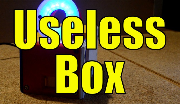
Another useless box
by Thingiverse
Last crawled date: 4 years, 2 months ago
3D printed useless box. Arduino driven. Features 4 servos and a gesture/proximity sensor. Contains a 16 LED neopixel ring. All parts are easy to source. Sketch and pcb files can be found at Github, see below. Also available at Thingiverse und Prusaprinters.
Video containing some more footage:https://www.youtube.com/watch?v=pDcApzEbbxg
uselessbox
Just another useless box
3D printed useless box or so called useless machines. Arduino driven. Features 4 servos and a gesture/proximity sensor. Contains a 16 LED neopixel ring. All parts are easy to source.
List of parts, sources (no affiliate links)
1x Arduino Nano V3 5V
1x Gesture/proximity sensor, 5V (!) similar to https://www.distrelec.de/de/naeherungs-licht-rgb-und-gestensensor-apds9960-5v-adafruit-3595/p/30139163
1x switch, similar to https://www.amazon.de/gp/product/B07MY2WVQ3/
1x jack similar to https://www.amazon.de/gp/product/B009PH1J5Y/
1x power adaptor similar to https://www.amazon.de/gp/product/B07HSPT57Y
4x servo motors, similar to https://www.amazon.de/gp/product/B06XQD18QN
cables, solder stuff
22x M3*10 scews
5x M3*8 screws
2x M3*20 screws
1x Neopixel 16 LED ring similar to https://www.distrelec.de/de/neopixel-ring-mit-16-rgb-leds-adafruit-1463-neopixel/p/30091142
1x resistor 1/4W 260 Ohm
1x resistor 1/4W 10 kOhm
20x 2.54mm pin headers
2x 5mm 2pol screw terminals
some steering servo push wire, 0.6mm will do. You need about 10 cm.
some double sided tape
optional: stuff to create PCBs
Instructions
Optional: create your PCB
Just 3d print the parts, each part one time. I printed the "OK fingers" in 0.1mm, and all other stuff in 0.25mm. I used cubic infill, 2 shells, and 3 shells on bottom and top. I did not use any support except for the LED housing. I was using PLA from https://dasfilament.de
Mount one servo to the back part. The axis on top is showing to the outside. Add the lid servo arm. Mount the lid to the back using M3*20 screws. Now use the steering servo push wire. Make sure your servo is at center position when doing that. Make the wire as long as you need it so the lid and back are located rectangular.
Mount the back to the bottom, using 4 M3*10 screws.
Mount the usb door using the usb door frame, to the the front. Mount the front to the bottom using 4 M3*10 screws.
Mount the jack to the bottom rear and lock it using the "Buchsenhalter" (sorry, forgot to translate it) to the bottom. Use 2 M3*8 screws.
Solder 5 cables to the gesture sensor board, but do not use the pins for this breakout board. If you have, use some old servo cable or anything similar that would match to pins at your main board if you use any. If there are no pins, you will have to solder the wires to the main board later. Make the cables around 15cm long. Mount the sensor board to the top, using the Sensorlock and 2 M3*8 screws.
Solder 2 cables to your switch. Mount the switch to the top. The "on position" of the switch has to show away from the sensor board. Make these cables around 15cm long.
Solder 3 more cables to your neopixel ring (ground, V+, data in). Make these cables 15 cm long, and use again some old servo cables or other cables matching pins. Add the neopixel ring to the housing, and close it using the LED cover. Btw, print this in transparent filament, if you have. Nice light effects are waiting for you. Lock the housing and the cover by another M38 screw. The neopixel ring points towards the cover with its LEDs. Mount the LED housing on top of your top part, and lock it using some M310 screws. The LED point towards the front. Moint the "flag arm" to one servo, and this servo to the top part. If you look from behind, the axis points to you and to the left. You can add some white label to the flag holder, to create a small flag. Mount the top to the front using another 4 M3*10 screws.
Mount the finger to one servo, do not lock it up yet. Mount the servo to the right housing part, axis to the right. Mount the right housing to the already mounted parts, mount it on the right side when you look from behind! Use 5 M3*10 screws.
OK, we enter the finish line, slowly...
Mount the 4th servo to the "left" part. Axis point to the front, but downwards. Connect OK fingers and "assholearm" together using another M3*10 screw. Mount the whole arm to the servo. DO NOT CLOSE THE HOUSING YET!
Connect all wires (servos, LED, switch, jack, gesture sensor) to your PCB. Take care for not short cutting anything. Use double sided tape and mount your PCB in a way you can reach the USB of te arduino throught the "usb door" at the front of your housing. Make sure again you do not block any servo movement by cables.
It is time to connect the power adaptor. If nothing smokes, you got your solder job the right way.
Make sure the switch on top of your new toy is in Off position, pointing to the front. Connect USB and your PC. Fire up your Arduino IDE, load the sketch and push it to the Arduino. Maybe you need to activate libraries for servos, or FastLED or the gesture sensor. Just follow the instruction of these vendors.
After the reboot, the LED should light up in blue and kind of glow...if you put your finger on the sensor, it should glow red, brightness depending on how close your finger is to the sensor.
At the same time, all your servos were "reset". You can now tighten all the screws of the servo arms connecting to the servo heads.
Servo for Lid: in reset position the LID should be closed
Servo for Flag: in reset position the flag arm should be horizontal, but below the edge of the top.
Servo for OKFinger/Asshole: The door should be closed, the fingers hidden.
Servo for Finger: Tricky one. Push the switch backwards and watch your finger if it makes it way to the switch. Idealy, it should turn the switch off. Just adjust until this happens. Hint: give a little extra push, just about 2-3 mm. Finally, tighten the screw.
OK, if all mechanics are working as expected, your useless machine should work as expected. You can now close the housing, using the last 5 M3*10 screws.
What does it do?
Basically, the Arduino will cycle trough different ways the servos work. To start the machine, just push the switch to on. The main task of this machine is to push the switch into its off position.
Step 1: open lid, push switch off
Step 2: open lid very harsh, push switch off. After that the lid will open depending on how close your finger is to the sensor.
Step 3: open lid again, push switch off
Step 4: open lid, waving white flag, close the lid. Open the lid, push off the switch, close the lid.
Step 5: show the OK finger / asshole finger (as you prefer), then open the lid, push the switch, close the lid.
Of course you are invited to extent the possible action, color codes and so on. Just make sure to not use "delay()" too heavy, since this will interrupt the glowing of the LED.
Frequently asked questions
Why do you enable and disable the servos that much?
I found my servos to be really cheap ones. They interfere with each other. Disabling the servos I do not need for the moment solved this. However, in the video you can see the servos "choking". If you can, buy quality servos.
Credits
The "OK finger" was remixed out of https://www.thingiverse.com/thing:3370059 by tdkahn1978 .
Crosslinks
Repohttps://github.com/pstimpel/uselessbox
Thingiversehttps://www.thingiverse.com/thing:3901482
Prusaprintershttps://www.prusaprinters.org/prints/6042-another-useless-box
Similar models
thingiverse
free

Finger and bracket mounting for useless box by dgrover
... servo at correct position for finger. servo, finger movements and switch can then be controlled by programming an arduino board.
thingiverse
free

Adafruit 16 NeoPixel Ring Mount by oshoham
...ount to the underside of a 1/8" enclosure panel.
i used this grabcad model of the 16 neopixel ring to help design the mount.
thingiverse
free

A5 Face Tracker by cynthisl
...he servo, can be screwed into box lid
bunny mount - holds sonar sensor and leds, is meant to go on top of servo and be screwed in
thingiverse
free

The Useless Arduino with LED by yamauratetsuya
...ing is based on useless arduino "https://www.thingiverse.com/thing:415296".
it's made a hole for led beside switch.
thingiverse
free

Easier Useless Box TowerPro SG90 by blarbles
...he micro lever roller arm is depressed when you finalize the arm position.
(optional) glue letters if you used the top with text.
thingiverse
free

Arduino Nano Base for Modern Style Christmas Tree
...e code, change the extension on file "modern_xmas_tree-7.txt" to .ino and save it in a folder called modern_xmas_tree-7
thingiverse
free

Arduino Nano Holder by hpflatorre
...ingiverse
arduino nano mount with m3 screw slots.
this mount was designed to hold a board with the pins soldered to the top side
thingiverse
free

8-LED Neopixel Stripe holder (OpenScad), 2 mount versions, fully parametric by HenningS
...pe can be switched and adapted in openscad source. as provided it fits to my diatone fpv 250 quad with 28mm fixing hole distance.
thingiverse
free

Stryfe integrated Firefly system by Z0r4n
... 16awg cables + 2 cables for the led. drill the led mount to put the leds, solder and screw it on the top of your stryfe jamdoor.
grabcad
free

20 cents Ender 3 V2 Filament Sensor
...as shown in the last picture.
you may need a longer m3 screw to secure it in place where the threaded nut of the z-axis is fixed.
Useless
3d_export
free

aluminum baseball bat
...for unity engine:<br>albedo<br>metallic smoothness(glossiness map in alpha)<br>normalmap-opengl format (almost useless here)<br>resolution 2048x2048<br>created in blender...
3d_ocean
$4

Old Tyres Texture
...repetition rubber seamless stacked texture tire tires traction tyre useless wallpaper waste wet wheel wheels old tyres seamless background...
3d_export
$17

belt grinder sander buffer edge polishing machine
...metals tend to clog grinding wheels, quickly making them useless for grinding soft metals. because the small grooves in...
thingiverse
free

Useless Machine / useless box by alchemico
...ine || useless box.
youtube - https://www.youtube.com/watch?v=g_el7c-3i6c&t=61s
i encourage you to subscribe to this channel.
thingiverse
free

Useless Dice With Useless Gear File by Ilslaoaycd
...useless dice with useless gear file by ilslaoaycd
thingiverse
dice with gear cutouts, included the gear file.
useless
thingiverse
free

Useless test by kbs3056
...useless test by kbs3056
thingiverse
useless test
thingiverse
free

Useless Box by mandle
...useless box by mandle
thingiverse
useless box
youtube
thingiverse
free

Useless thing by P_Suarof
...useless thing by p_suarof
thingiverse
useless thing (3d studio)
thingiverse
free

Useless Box by felixbieri
...useless box by felixbieri
thingiverse
this is a prototype of my useless box.
https://youtu.be/iki6ncnkls0
thingiverse
free

Useless Box by Tupsy
...useless box by tupsy
thingiverse
a remix of the useless box.
this one has a gearing, to run longer.
Another
turbosquid
$15
ANOTHER BATHROOM
...quid
royalty free 3d model another bathroom for download as on turbosquid: 3d models for games, architecture, videos. (1171460)
turbosquid
$24

Another World
... available on turbo squid, the world's leading provider of digital 3d models for visualization, films, television, and games.
turbosquid
$39
Another Red Curb
...ee 3d model another red curb for download as ma, obj, and fbx on turbosquid: 3d models for games, architecture, videos. (1182913)
turbosquid
$9

Another Deberenn Sofa
...model another deberenn sofa for download as max, obj, and fbx on turbosquid: 3d models for games, architecture, videos. (1497850)
turbosquid
$2

Another picnic table
... model another picnic table for download as max, obj, and fbx on turbosquid: 3d models for games, architecture, videos. (1426381)
turbosquid
$15

door to another world
...oor to another world for download as 3ds, obj, fbx, and blend on turbosquid: 3d models for games, architecture, videos. (1334842)
3d_export
free
another hacksaw
...another hacksaw
3dexport
. . . 3d model of a hacksaw. 3d model files: - 3ds max 2017 (scanline) - obj (low poly) . . .
turbosquid
$12

Another Country Side Table
... another country side table for download as max, obj, and fbx on turbosquid: 3d models for games, architecture, videos. (1496053)
turbosquid
$29

Furniture - "Another country" modern sofa
...another country" modern sofa for download as obj and c4d on turbosquid: 3d models for games, architecture, videos. (1186189)
3d_ocean
$29

Another Tron Light Cycle with the Rider and Trail
...ther tron light cycle with the rider and the light trail. high quality 3d model,all the materials and lights are included. the...
Box
archibase_planet
free
Box
...box
archibase planet
box carton cardboard box
box 2 - 3d model (*.3ds) for interior 3d visualization.
archibase_planet
free
Box
...box
archibase planet
carton cardboard box box
box 1 - 3d model (*.3ds) for interior 3d visualization.
3d_export
$6
box
...box
3dexport
box
3d_export
$5
Box
...box
3dexport
box
3d_export
$5
box
...box
3dexport
box
3d_export
$5
box
...box
3dexport
box
archibase_planet
free
Box
...box
archibase planet
box box for paper notebook pencil
box - 3d model (*.gsm+*.3ds) for interior 3d visualization.
archibase_planet
free

Box
...box
archibase planet
box carton cardboard box
box n170111 - 3d model (*.gsm+*.3ds) for interior 3d visualization.
archibase_planet
free

Box
...box
archibase planet
box carton cardboard box
box n050411 - 3d model (*.gsm+*.3ds) for interior 3d visualization.
archibase_planet
free

Boxes
...boxes
archibase planet
boxes box case bin
boxes n281213 - 3d model (*.gsm+*.3ds+*.max) for interior 3d visualization.