Thingiverse
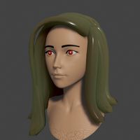
Anet A8 Print Head Micrometer Height Adjuster by sportssedan
by Thingiverse
Last crawled date: 3 years ago
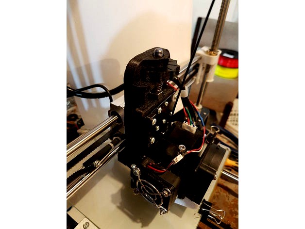
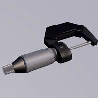
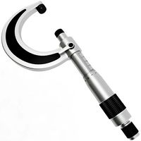
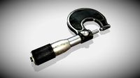
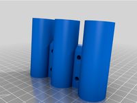
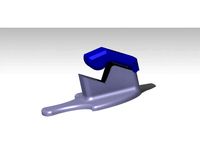
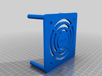
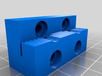
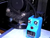
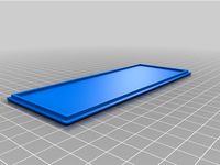
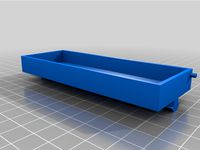
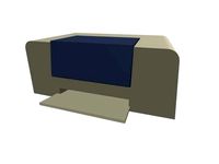
This is a Anet A8 Micrometer height adjuster for the print head .The back half fits directly onto the 3 linear bearing blocks the same as the original aluminium bracket , & uses all original screws for mounting . An adjustable dovetail wedge plate slides into the rear mount & the original Print head/extruder screw directly to this plate using 3mm x 10mm self tapping screws . An Inductive sensor mount is also provided , in 12mm & 18mm sizes to mount a sensor .
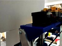
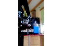
A piece of 8mm x 1mm fine pitch threaded rod ( or 5/16 UNF can be used too) x 140mm long & 3 nuts are needed for the variable height adjuster .A thumb wheel with 10 graduated l markings is used to adjust the height . This gives a resolution of 0.1mm ( 0.004") per graduation & allows the head 12mm of variable height adjustment .A compression spring 25mm long x 10mm is used to Take all backlash out of the design , as well stop any vibrations
Adjustments can be made while the machine is printing , so if a brim layer appears to be slightly too high or low , it can be adjusted immediately with out having to stop printing or adjust the control panel .
Adjustments are completely independent of all electronics, sensors & home switches etc, So once an adjustment has been made it will remain constant for all further prints .
Whilst there are electronic adjustments & updated firmware available , & the sensor upgrade has drastically improved Z axis calibration , i still find this device particularly useful to make fine & accurate adjustments quickly on the go.
The 2 dovetail wedge parts should be a neat , almost a little tight , so there is no movement or vibration between the 2 parts .
If they are too tight , just pear some plastic away with a sharp knife until the fit is correct .
You will loose 20mm of Y axis with the additional thickness of the mount , but you can get most of that back by spacing the Y axis home micro switch forward as there is some room left on the Y axis sliders ,You an also change the offsets in the arduino firmware if your confident editing arduino code. Just make sure you measure everything & re-calibrate your slicer software for your maximum Y travel & test that you don't exceed axis travel .
You will also need some M3 x 40mm Countersunk screws & nuts for the sensor mount & the belt mounting pins .
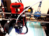
Update :(April 8 2017) Just added a mount to fit a Bowden E3D -V6 Extruder head that screws directly to the Front Slider Mount at (http://www.thingiverse.com/thing:2236009)
Update: 12/4/2017 added a sensor mount for the Tronix XY08n sensor
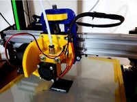
Update : 8/5/2017 Just added a sensor mount for a 30mm diamater proximity sensor. Its ugly but it has a 15mm Sensing range , so it is much better & has much more clearance when using a glass table .
A piece of 8mm x 1mm fine pitch threaded rod ( or 5/16 UNF can be used too) x 140mm long & 3 nuts are needed for the variable height adjuster .A thumb wheel with 10 graduated l markings is used to adjust the height . This gives a resolution of 0.1mm ( 0.004") per graduation & allows the head 12mm of variable height adjustment .A compression spring 25mm long x 10mm is used to Take all backlash out of the design , as well stop any vibrations
Adjustments can be made while the machine is printing , so if a brim layer appears to be slightly too high or low , it can be adjusted immediately with out having to stop printing or adjust the control panel .
Adjustments are completely independent of all electronics, sensors & home switches etc, So once an adjustment has been made it will remain constant for all further prints .
Whilst there are electronic adjustments & updated firmware available , & the sensor upgrade has drastically improved Z axis calibration , i still find this device particularly useful to make fine & accurate adjustments quickly on the go.
The 2 dovetail wedge parts should be a neat , almost a little tight , so there is no movement or vibration between the 2 parts .
If they are too tight , just pear some plastic away with a sharp knife until the fit is correct .
You will loose 20mm of Y axis with the additional thickness of the mount , but you can get most of that back by spacing the Y axis home micro switch forward as there is some room left on the Y axis sliders ,You an also change the offsets in the arduino firmware if your confident editing arduino code. Just make sure you measure everything & re-calibrate your slicer software for your maximum Y travel & test that you don't exceed axis travel .
You will also need some M3 x 40mm Countersunk screws & nuts for the sensor mount & the belt mounting pins .
Update :(April 8 2017) Just added a mount to fit a Bowden E3D -V6 Extruder head that screws directly to the Front Slider Mount at (http://www.thingiverse.com/thing:2236009)
Update: 12/4/2017 added a sensor mount for the Tronix XY08n sensor
Update : 8/5/2017 Just added a sensor mount for a 30mm diamater proximity sensor. Its ugly but it has a 15mm Sensing range , so it is much better & has much more clearance when using a glass table .
Similar models
thingiverse
free
Anet A8 Bowden E3D-V6 print head mounting to suit Micrometer Height Adjuster by sportssedan
...ht adjuster parts. you will need to drill the holes out a little but mounting hole centers match the anet bearing plumber blocks.
thingiverse
free
Hotend Micrometer Height Ajuster for 20/20 & 20/40 Extrusion by sportssedan
... you find this useful please like & post some finished photos .
added youtube vid https://www.youtube.com/watch?v=fzpfhl9lbni
thingiverse
free

Micrometer Head Z-axis endstop mount by pefozzy
... to use as the adjustable z-axis endstop.
also includes the lower mount for the switch and rod clamp to hold it to a 10mm rod.
thingiverse
free

SK-Tank Y-Axis Sensor Mount by doumas
... location. don't forget to diddle the y-axis dimension in your configuration file to make use of the additional build volume.
thingiverse
free

Fast Precise Z-Height Adjustment by Micrometer by nangpae
...0-13mm/152482739647?sspagename=strk%3amebidx%3ait&_trksid=p2057872.m2749.l2649
this fixture is for kodama trinus 3d printer.
thingiverse
free

J Head Bowden mount with fan and prox by BubaLettow
...also has a hole for an adjustment screw for x axis endstop.
prints tight maybe print at 101% depending on shrinkage of filament.
thingiverse
free

flsun prusa i3 sensor mounts by netsplit
...ouch version was too low, so i've adjusted it. if its too high, just use some nuts to lower it
updated - added in sn04 sensor
grabcad
free

Sensor adjustment in X and Y
...sensor adjustment in x and y
grabcad
sensor adjustment in x and y axes using a screw drive
thingiverse
free

Low profile Y axis tensioner Ender 3 Pro by jonasgddfr
...9;ve added the .step file if you want to make adjustments of your own.
don't forget to link if you remix ;) much appreciated!
thingiverse
free

height adjustment z axis by bandit-ed
...st the hight with a accuracy of 0,01 mm .
(within the sensor block is a steel bold mounted so the contact surface is steel/steel)
Sportssedan
thingiverse
free

Anet A8 rear frame by sportssedan
...ss frame for anet a8. avaliable in several designs & also a split version with a joiner, for printing on 200mmx200mm printers
thingiverse
free

HINGE 182 DEG by sportssedan
...frame i was building . it uses an m4 bolt for the pin , & can layback a full 180 deg , plus a couple of extra for clearance .
thingiverse
free

Tilton Master cyl Reservoir Lid by sportssedan
...
print with top up, as the buttress thread will string if printed upside down .
2 versions available, with or without some logos.
thingiverse
free

Longacre Battery Isolator Insulator/cover by sportssedan
...witch with a 40 x 25mm access hole for the wiring & an end cap , held on wih 3 x 3mm x 10mm countersunk self tapping screws .
thingiverse
free

Electrical Switch 6mm Square Drive by sportssedan
...; captive nut & grub screw to secure. could be used on any switch gear using a 6mm square drive . may be usefull to someone.
thingiverse
free

Hanging Bracket for Filament Spools by sportssedan
...ersion . re-scale the z axis in your slicer if you want to thin it down a bit . currently carrying 7 x 1kg spools with no issues.
thingiverse
free
20-40 Stepper Motor Mount by sportssedan
...on top .
6 mounting holes on the top & side provide 90 deg mounting around the extrusion frame , giving a very solid mount .
thingiverse
free

Fuel Cap Briggs & Stratton 300 Series by sportssedan
... stratton mower engines .
printed in petg .
wouldn't recommend pla or abs as the fuel will probably react & dissolve it.
thingiverse
free
Gauge Protector 4" 100mm by sportssedan
...ication .the inside diameter where the gauge body fits is currently 99mm diameter & the depth to the internal step is 28mm .
thingiverse
free

Chipolo Credit Card Holder by sportssedan
...s , then just scale it slightly in your slicer sofware for a nice fit . hopefully this is useful to someone other than just me .
Micrometer
3d_ocean
$9
Micrometer
...r
3docean
measure meter micrometer micrometru micrometter tool tools
micrometer with materials and textures made in cinema 4d r14
3d_export
$50
Micrometer 3D Model
...ol industrial measure measurement precision accuracy tolerance dimension mike metric
micrometer 3d model plutonius 33278 3dexport
cg_studio
$50

Micrometer3d model
...ter3d model
cgstudio
.3ds .max .obj .wrl - micrometer 3d model, royalty free license available, instant download after purchase.
sketchfab
$10
Micrometer
...
sketchfab
one material 2k pbr metalness - quads - micrometer - buy royalty free 3d model by francesco coldesina (@topfrank2013)
3dfindit
free

Electronic-Micrometer
...electronic-micrometer
3dfind.it
catalog: dong-do electronics
thingiverse
free
3x Micrometer wall holder
...3x micrometer wall holder
thingiverse
wall holder for 3 micrometers.
thingiverse
free
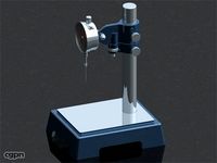
Micrometer stand by CyrilDomp
...micrometer stand by cyrildomp
thingiverse
a simple micrometer stand. m8*35 mm hexagon head screw and a m8 nut are required.
thingiverse
free

Micrometer Stand by smalla
...micrometer stand by smalla
thingiverse
a very simple one.
you need an m6 nut and an m6x16 (thumb) screw to fix the micrometer.
thingiverse
free

Depth Micrometer Holder by afant
...depth micrometer holder by afant
thingiverse
just a holder for my depth micrometer
thingiverse
free
Micrometer Lock Lever by carboncopy101
...micrometer lock lever by carboncopy101
thingiverse
replacement lever for the lock of my micrometer.
A8
turbosquid
$47

Car A8
...
turbosquid
royalty free 3d model car a8 for download as max on turbosquid: 3d models for games, architecture, videos. (1196060)
turbosquid
$50

Audi A8
...yalty free 3d model audi a8 for download as 3dm, obj, and fbx on turbosquid: 3d models for games, architecture, videos. (1580187)
turbosquid
$15

Audi A8
...lty free 3d model audi a8 for download as obj, fbx, and blend on turbosquid: 3d models for games, architecture, videos. (1387519)
turbosquid
$500

Audi A8
... available on turbo squid, the world's leading provider of digital 3d models for visualization, films, television, and games.
3d_export
$5

Audi A8 3D Model
...audi a8 3d model
3dexport
audi a8 cars car
audi a8 3d model ma 20351 3dexport
3d_export
$5

Audi A8 3D Model
...audi a8 3d model
3dexport
3d model of audi a8
audi a8 3d model badyaka 12136 3dexport
3d_ocean
$89

Audi A8 2010
...usiness car car class class f f german german luxury luxury s s s8 s8 sedan sedan vehicle vehicle
new audi a8 2010 detaled model.
turbosquid
$39

A8 2018
...a8 2018 for download as 3ds, obj, wrl, c4d, fbx, dae, and stl on turbosquid: 3d models for games, architecture, videos. (1345349)
turbosquid
free

audi a8 l
...rbosquid
royalty free 3d model audi a8 l for download as obj on turbosquid: 3d models for games, architecture, videos. (1663016)
3d_ocean
$45

Audi A8 restyled
...our door vehicle was created in blender3d 2.62.realistic renderings were created with yafaray 0.1.2 realistic plugin.rendering...
Anet
thingiverse
free

Anet by derbodesign
...anet by derbodesign
thingiverse
logo anet
thingiverse
free
Anet e10 , Anet v1.0 by jonathan_943D
...anet e10 , anet v1.0 by jonathan_943d
thingiverse
soporte de ventilador de 80mm, para controladora anet v1.0
thingiverse
free
Anet A8 Anet AM8 Y belt holder
...anet a8 anet am8 y belt holder
thingiverse
anet a8 anet am8 y belt holder
thingiverse
free
Anet A8 Probe Bracket for anet sensor by chelrix
...anet a8 probe bracket for anet sensor by chelrix
thingiverse
anet a8 probe bracket for anet official sensor and marlin firmware
thingiverse
free
Anet logo by JUST3D_PRNTNG
...anet logo by just3d_prntng
thingiverse
anet logo
thingiverse
free
Fan nozzle for Anet A8 with original Anet levelsensor by peteruhlmann
...et levelsensor by peteruhlmann
thingiverse
here is an improved fan nozzle for the anet a8 with original level sensor from anet.
thingiverse
free
Anet Et4 Box
...anet et4 box
thingiverse
tool box for anet et4
thingiverse
free
Anet Logo by Superflex_Plastic_Fantastic
...anet logo by superflex_plastic_fantastic
thingiverse
anet logo to incorporate into designs.
thingiverse
free
Box for Anet ET4
...box for anet et4
thingiverse
this is a simple box for tool of anet et4
thingiverse
free

Anet V1.0 Board Kühlung (80mm Lüfter) / Anet A8 by MadCre8
...anet v1.0 board kühlung (80mm lüfter) / anet a8 by madcre8
thingiverse
anet v1.0 board kühlung (80mm lüfter) / anet a8
Adjuster
3d_ocean
$7
Adjustable Wrench
...adjustable wrench
3docean
adjustable wrench highly detailed wrench
highly detailed adjustable wrench.
3ddd
$1
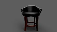
Adjustable Stool
...adjustable stool
3ddd
табурет
wooden adjustable stool.
3d_ocean
$20

Adjustable Gym Bench
...st adjustable bench black equipement gym gymnastic indoor silver sport workout
3d model of black and silver adjustable gym bench.
3d_ocean
$20
Adjustable Gym Bench
...st adjustable bench black equipement gym gymnastic indoor silver sport workout
3d model of black and silver adjustable gym bench.
3d_ocean
$16

Adjustable Weight Bench
...arbell bench black equipement gym gymnastic indoor sport weight workout
3d model of black adjustable weight bench with a barbell.
turbosquid
$5

Adjustable wrench
...
royalty free 3d model adjustable wrench for download as fbx on turbosquid: 3d models for games, architecture, videos. (1313414)
3d_export
$5
adjustable tension lock
...adjustable tension lock
3dexport
adjustable tension lock
turbosquid
$1

Adjustable Wrench
...free 3d model adjustable wrench for download as obj and blend on turbosquid: 3d models for games, architecture, videos. (1446736)
turbosquid
$1

Adjustable Wrench
...y free 3d model adjustable wrench for download as c4d and fbx on turbosquid: 3d models for games, architecture, videos. (1379022)
3d_export
$5

Adjustable key
...adjustable key
3dexport
Head
3d_export
$5

head
...head
3dexport
simulated female head.
3d_ocean
$5

Deer Head
...deer head
3docean
deer head
simple model of deer head with neck.
cg_studio
$25

Marble Head - Head A3d model
... - head a3d model
cgstudio
.ma - marble head - head a 3d model, royalty free license available, instant download after purchase.
turbosquid
$5
Head
...ad
turbosquid
royalty free 3d model head for download as max on turbosquid: 3d models for games, architecture, videos. (1230068)
turbosquid
free

Head
...
turbosquid
royalty free 3d model head for download as blend on turbosquid: 3d models for games, architecture, videos. (1276899)
turbosquid
free

The Head
...urbosquid
royalty free 3d model the head for download as max on turbosquid: 3d models for games, architecture, videos. (1386205)
3d_export
$10

bull head
...bull head
3dexport
bull head
3d_export
$5
girl head
...girl head
3dexport
head girl
3d_export
$5
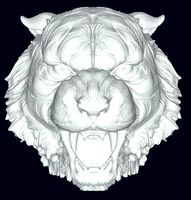
Tigger-head
...tigger-head
3dexport
tigger-head
3d_export
$5

head on a spear
...head on a spear
3dexport
head on a spear
Height
turbosquid
$5
Height Stool
...ree 3d model height stool for download as blend, obj, and fbx on turbosquid: 3d models for games, architecture, videos. (1703076)
cg_studio
$20
Height Gauge3d model
...ndustrial height gauge tool indutsrial
- height gauge 3d model, royalty free license available, instant download after purchase.
turbosquid
$6
4.5 meters in height
...oyalty free 3d model 4.5 meters in height for download as max on turbosquid: 3d models for games, architecture, videos. (1213038)
turbosquid
$1
Counter Height Stool
... model counter height stool for download as obj, dae, and skp on turbosquid: 3d models for games, architecture, videos. (1318792)
turbosquid
$10
low height cabinet
...ow height cabinet for download as max, max, fbx, obj, and max on turbosquid: 3d models for games, architecture, videos. (1545300)
turbosquid
$5
Counter Height Bench
... available on turbo squid, the world's leading provider of digital 3d models for visualization, films, television, and games.
3ddd
free
Stanley furniture - Avalon heights
...stanley furniture - avalon heights
3ddd
stanley furniture
stanley furniture - avalon heights metal base empire writing desk
3d_ocean
$1
Maximum height sign
...ure applied. the object is ready to import and render in both formats. the model has been built to be able to subdivide flawle...
turbosquid
$20

Low height cabinet design
...y free 3d model low height cabinet design for download as max on turbosquid: 3d models for games, architecture, videos. (1402496)
turbosquid
$15
Atlantis Bar Height chair
...y free 3d model atlantis bar height chair for download as max on turbosquid: 3d models for games, architecture, videos. (1271123)
design_connected
$27
...print
designconnected
moroso print computer generated 3d model. designed by wanders, marcel.
3ddd
free

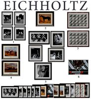
Eichholtz Prints
...- eichholtz print central station i
13 - eichholtz print central station ii
14 - eichholtz print marisa
15 - eichholtz print tish
3ddd
$1

Eichholtz Prints
...print abstract - set of 2
10 - eichholtz print orange abstract
11 - eichholtz print buddha right
12 - eichholtz print buddha left
turbosquid
$1
... available on turbo squid, the world's leading provider of digital 3d models for visualization, films, television, and games.
3ddd
free

Eichholtz Prints
...of 4
2 - print dunbar 2 set of 4
3 - print guadeloupe 1 set of 4
4 - print guadeloupe 2 set of 4
5 - print giles
6 - print trett
3ddd
$1

Eichholtz Prints
...nt tutti frutti
3 - eichholtz prints watson - set of 2
4 - eichholtz prints antique nautilus - set of 2
5 - eichholtz print tiara
3d_export
$5
Monster for printing
...monster for printing
3dexport
monster 3d model printing
3ddd
free
printed rug
...printed rug
3ddd
ковер
very creative printed rug
3ddd
free
Eichholtz Prints
...иал: бумага
габариты (вхш): 72 x 62 см
описание: print sweetmeat - постер в деревянной раме.
3 - prints varsity set of 2
арти
3ddd
free
Art Print Posters
...art print posters
3ddd
прованс
art print posters by patrician prints