Thingiverse
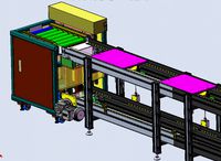
Anet A8 Double Heat Bed (220x440x220) by EllisDee
by Thingiverse
Last crawled date: 3 years ago
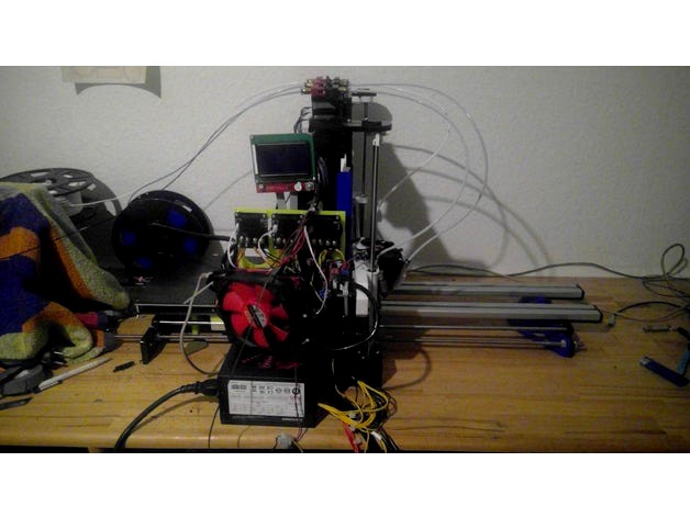
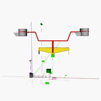
Anet A8 Double Heat Bed
At first i have to say thanks to SmallArtFly for making the Anet A8 frame in useable CAD files
All links are just samples
Warning!!!
not possible with 20A Power supply you will smoke it up
you need around 30A for this. Every Heat bed has 10A and start to use mosfet boards,
its not useful to send so much ampere over the Mainboard
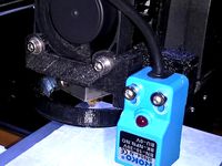
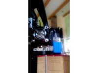
Also i suggest you to solder the wires directly onto the heat bed, my plug smoked up.
as far as i know, they all do sooner or later. for second heat bed u have to remove the plug, and solder the wires directly onto the heat bed.
also you need to add additional lead, the 8mm steel is too weak and starts bouncing on print
sry im no instructions guy hope it will help what i wrote and is understandable ^^
feel free to ask, and maybe u get answered ;-)
Parts Needed
1x Heat Bed 220x220
(must be the same like the other one, cause u cant temperate them alone and have to use 2 beds parallel with just 1 PTC. But works pretty well they have nearly same temperature the difference here is around 2°c maybe with firmware changes it will be possible but still did not figured out how)
2m GT2 Belt
2x heat bed springs
(they are needed for the middle u need to arrange the print head distance there too
so you will have 6 points to level the bed after extending)
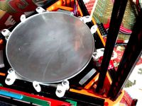
2x aloy or carbon plate 440x220x4 for heat bed carrier stability and as print bed
(i used Carbon around 170€ but u can print directly on it and its rly stable at 4mm)
2x 1m silver steel rod 8mmhttp://www.ebay.de/itm/Silberstahl-8mm-Rund-1-2210-geschliffen-poliert-Länge-1000mm/172521494796?ssPageName=STRK%3AMEBIDX%3AIT&_trksid=p2060353.m2749.l2649
2x 1m VA screw 8mm
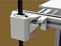
2x I-Typ Profile 40x16x1000 With Drillholes through the whole lentgh of profilehttp://www.ebay.de/itm/Aluminiumprofil-40x16S-I-Typ-Nut-8-Zuschnitt-50-1190mm-11-50-EUR-m-min-1-EUR-/282225635697?var=&hash=item41b5f57171:m:m_hMGu-VQluYoLY24kAYgxw
(needed for Stability if not used or something like this the heat bed starts bouncing prints get ruined for sure and the silver steel rod / bearings maybe gets damaged this profiles are rly stable)
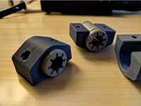
16x bearing 3x6x2,5mm (for the sleds)http://www.ebay.de/itm/10-x-Kugellager-Bearing-63-ZZ-3x6x2-5mm/151965772109?ssPageName=STRK%3AMEBIDX%3AIT&_trksid=p2060353.m2749.l2649
M3 x20mm screws
for the i typ profile, make sure u screw some m3 screw through the plastic
before trying to make them in place, else they break, they are weak and just
for holding in place. if everything is ok threy dont get any forces on the I-typ
Profile just pressure from top cause of heat bed
8x M3 x 20mm screws
for the sled, to hold the bearings. Let them stand out some mm that the screws / sled
cant get over the linear bearings u will see that at assembling
the sleds dont get screwed at the heat bed carrier u can do it but i didnt, on this way the sleds cant leave place when pressure from bed is too low or not 100% parallel.
Also make sure u cleaned the bearing holes well from plastic the bearings must be able to turn very well, make some points with water proof pen on it is u had problems like me to see it turning. the screw holes should be drilled with 2.5mm then the screws make their own thread but u could use also a 3mm thread drill
Also i would suggest u to change the common linear bearings to plastic ones, maybe i just got bad bearings but they already destroied a silver steel rod and the new one has a scratch too
have them here but still not in usehttp://www.ebay.de/itm/8x-DryLin-Igus-RJ4JP-01-08-Gleitlager-anstelle-LM8UU-RepRap-Mendel-Linearlager/272135737892?ssPageName=STRK%3AMEBIDX%3AIT&_trksid=p2060353.m2749.l2649
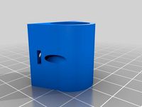
there gets nothing rly screwed together it holds by its own thats why i cant help with the front holders, you need to create them by yourselft they depend on how long your i-typ profiles will be.
my silver steel rods are 77cm
my VA screws are 82 cm (yes i know i still didnt sawed them.... too lazy to disassamble )
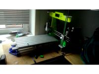
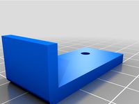
my I-typ Profile is around 84 cm and 78 but as u can see in picture i messed it up^^ need a course in how to measure :-) and thats why you need to make the front holders by your own ;-) the front holder i posted is just a suggestion how to
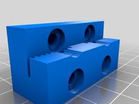
to build the new heat bed carrier take the old one and mark the holes of it on the 440cm aloy or carbon 2 times that u have the holes for the linear bearings you just need the middle bearing holes and 4 bearings, but u need the holes at the side for endstop, be creative to make sure you reach it, i used a 2cm linearbearing spacer and the small block. u can compensate it in firmware also but if no endstop blöck is used heatbed carrier maybe crashes at the wall not good for your belt. Could be used to expend the heat bed a lil but there still should be heat at the edges of bed ^^
you need to place the 2cm blocks between linear bearing and heat bed carrier to make space for the i typ profile.
place the i typ profile spacers on 1/4 and 3/4 of travel way. place the i typ profile on the spacers and top /back acryl plates. the other one gets holded under the stepper. there should be now around 1mm space between bearing blocks and profile. put the sleds on it in the middle of carrier. if the sleds are too low, use some thick paper between sled and carrier (sand paper sand side on sled)
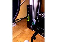
use the screws from the 8mm steel rod holders to add the additional i typ profile holders at the back u can use one of the spare part holders, this prevents the i typ proile from sliding backwards at the other side u take the ones i made to prevent the profile from sliding forward.
Made some spacers today for the profile to prevent them from bending and to keep them parallel, you should be able now to arrange the i typ profiles now easy between the linear beerings. be sure to put the sleds in before assembling the heat bed carrier, i dont think it will be possible later with spacers to get them into the middle
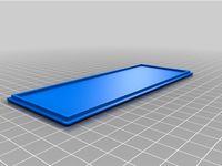
you should use some additional plate now were u screw the heat bed at i would suggest a material were you can print directly on it else use alloy, this is needed to have a plane surface with no edge coming up from one heat bed, i used 6x 30mm and 2x 12mm screws but i would suggest you to use 35 - 40mm makes it easier for the knurled nuts to get on
assemble the carrier like the old one only difference u will level the carrier not from top now, so u need some knurled nut, or cut a m3 thread into the alloy like it was made at the old carrier, not possible with carbon i think but i think its a bad solution cause u cant screw the heatbeds under the print surface tight with nuts. also u have now 6 points to level the Heat bed
Electric:
i use 3 mosfets for the reason that i use an ATX power supply with 60A double rail
2x 12v 30A so i can separate one heat bed to each rail, extruder on rail 1 mainboard on rail 2, and maybe later its possible to heat the bed separate and measure its temp
need to say it again!
solder the wires directly on bed, this plug is a real danger!!!! he can cause fire and burn down your house i saw it to the right time, plug got molten, some cm from the cables too, i think next print he had burned with luck just a shortcut
will post details on electric later if someone needs it
I am using the skynet firmware, works for Arduino 1,0 board and ramps 1.4 board very well
but since i have a diamond hotend im using a ramps 1.4 with cnc shield
Firmware:
You need to tell the machine that it has now the double Y axis length to do so change in
Configuration.h under "// Travel limits after homing (units are in mm)" for "#define Y_MAX_POS 220" and change it to 440 or how long your heat bed is.
feel to be inspired its all just a suggestion :-)
At first i have to say thanks to SmallArtFly for making the Anet A8 frame in useable CAD files
All links are just samples
Warning!!!
not possible with 20A Power supply you will smoke it up
you need around 30A for this. Every Heat bed has 10A and start to use mosfet boards,
its not useful to send so much ampere over the Mainboard
Also i suggest you to solder the wires directly onto the heat bed, my plug smoked up.
as far as i know, they all do sooner or later. for second heat bed u have to remove the plug, and solder the wires directly onto the heat bed.
also you need to add additional lead, the 8mm steel is too weak and starts bouncing on print
sry im no instructions guy hope it will help what i wrote and is understandable ^^
feel free to ask, and maybe u get answered ;-)
Parts Needed
1x Heat Bed 220x220
(must be the same like the other one, cause u cant temperate them alone and have to use 2 beds parallel with just 1 PTC. But works pretty well they have nearly same temperature the difference here is around 2°c maybe with firmware changes it will be possible but still did not figured out how)
2m GT2 Belt
2x heat bed springs
(they are needed for the middle u need to arrange the print head distance there too
so you will have 6 points to level the bed after extending)
2x aloy or carbon plate 440x220x4 for heat bed carrier stability and as print bed
(i used Carbon around 170€ but u can print directly on it and its rly stable at 4mm)
2x 1m silver steel rod 8mmhttp://www.ebay.de/itm/Silberstahl-8mm-Rund-1-2210-geschliffen-poliert-Länge-1000mm/172521494796?ssPageName=STRK%3AMEBIDX%3AIT&_trksid=p2060353.m2749.l2649
2x 1m VA screw 8mm
2x I-Typ Profile 40x16x1000 With Drillholes through the whole lentgh of profilehttp://www.ebay.de/itm/Aluminiumprofil-40x16S-I-Typ-Nut-8-Zuschnitt-50-1190mm-11-50-EUR-m-min-1-EUR-/282225635697?var=&hash=item41b5f57171:m:m_hMGu-VQluYoLY24kAYgxw
(needed for Stability if not used or something like this the heat bed starts bouncing prints get ruined for sure and the silver steel rod / bearings maybe gets damaged this profiles are rly stable)
16x bearing 3x6x2,5mm (for the sleds)http://www.ebay.de/itm/10-x-Kugellager-Bearing-63-ZZ-3x6x2-5mm/151965772109?ssPageName=STRK%3AMEBIDX%3AIT&_trksid=p2060353.m2749.l2649
M3 x20mm screws
for the i typ profile, make sure u screw some m3 screw through the plastic
before trying to make them in place, else they break, they are weak and just
for holding in place. if everything is ok threy dont get any forces on the I-typ
Profile just pressure from top cause of heat bed
8x M3 x 20mm screws
for the sled, to hold the bearings. Let them stand out some mm that the screws / sled
cant get over the linear bearings u will see that at assembling
the sleds dont get screwed at the heat bed carrier u can do it but i didnt, on this way the sleds cant leave place when pressure from bed is too low or not 100% parallel.
Also make sure u cleaned the bearing holes well from plastic the bearings must be able to turn very well, make some points with water proof pen on it is u had problems like me to see it turning. the screw holes should be drilled with 2.5mm then the screws make their own thread but u could use also a 3mm thread drill
Also i would suggest u to change the common linear bearings to plastic ones, maybe i just got bad bearings but they already destroied a silver steel rod and the new one has a scratch too
have them here but still not in usehttp://www.ebay.de/itm/8x-DryLin-Igus-RJ4JP-01-08-Gleitlager-anstelle-LM8UU-RepRap-Mendel-Linearlager/272135737892?ssPageName=STRK%3AMEBIDX%3AIT&_trksid=p2060353.m2749.l2649
there gets nothing rly screwed together it holds by its own thats why i cant help with the front holders, you need to create them by yourselft they depend on how long your i-typ profiles will be.
my silver steel rods are 77cm
my VA screws are 82 cm (yes i know i still didnt sawed them.... too lazy to disassamble )
my I-typ Profile is around 84 cm and 78 but as u can see in picture i messed it up^^ need a course in how to measure :-) and thats why you need to make the front holders by your own ;-) the front holder i posted is just a suggestion how to
to build the new heat bed carrier take the old one and mark the holes of it on the 440cm aloy or carbon 2 times that u have the holes for the linear bearings you just need the middle bearing holes and 4 bearings, but u need the holes at the side for endstop, be creative to make sure you reach it, i used a 2cm linearbearing spacer and the small block. u can compensate it in firmware also but if no endstop blöck is used heatbed carrier maybe crashes at the wall not good for your belt. Could be used to expend the heat bed a lil but there still should be heat at the edges of bed ^^
you need to place the 2cm blocks between linear bearing and heat bed carrier to make space for the i typ profile.
place the i typ profile spacers on 1/4 and 3/4 of travel way. place the i typ profile on the spacers and top /back acryl plates. the other one gets holded under the stepper. there should be now around 1mm space between bearing blocks and profile. put the sleds on it in the middle of carrier. if the sleds are too low, use some thick paper between sled and carrier (sand paper sand side on sled)
use the screws from the 8mm steel rod holders to add the additional i typ profile holders at the back u can use one of the spare part holders, this prevents the i typ proile from sliding backwards at the other side u take the ones i made to prevent the profile from sliding forward.
Made some spacers today for the profile to prevent them from bending and to keep them parallel, you should be able now to arrange the i typ profiles now easy between the linear beerings. be sure to put the sleds in before assembling the heat bed carrier, i dont think it will be possible later with spacers to get them into the middle
you should use some additional plate now were u screw the heat bed at i would suggest a material were you can print directly on it else use alloy, this is needed to have a plane surface with no edge coming up from one heat bed, i used 6x 30mm and 2x 12mm screws but i would suggest you to use 35 - 40mm makes it easier for the knurled nuts to get on
assemble the carrier like the old one only difference u will level the carrier not from top now, so u need some knurled nut, or cut a m3 thread into the alloy like it was made at the old carrier, not possible with carbon i think but i think its a bad solution cause u cant screw the heatbeds under the print surface tight with nuts. also u have now 6 points to level the Heat bed
Electric:
i use 3 mosfets for the reason that i use an ATX power supply with 60A double rail
2x 12v 30A so i can separate one heat bed to each rail, extruder on rail 1 mainboard on rail 2, and maybe later its possible to heat the bed separate and measure its temp
need to say it again!
solder the wires directly on bed, this plug is a real danger!!!! he can cause fire and burn down your house i saw it to the right time, plug got molten, some cm from the cables too, i think next print he had burned with luck just a shortcut
will post details on electric later if someone needs it
I am using the skynet firmware, works for Arduino 1,0 board and ramps 1.4 board very well
but since i have a diamond hotend im using a ramps 1.4 with cnc shield
Firmware:
You need to tell the machine that it has now the double Y axis length to do so change in
Configuration.h under "// Travel limits after homing (units are in mm)" for "#define Y_MAX_POS 220" and change it to 440 or how long your heat bed is.
feel to be inspired its all just a suggestion :-)
Similar models
thingiverse
free
Anet A8 Mill / Engraving Machine by EllisDee
...600 but depends on your leadscrew and steppers and must be calculated!!!!!http://www.prusaprinters.org/calculator/#stepspermmlead
thingiverse
free
Cetus3D z axis stabilization by Steamkraft
...- it may be enough but i like to get secure and use the thicker one :)
if you try the slim version, let me know what you think :)
thingiverse
free

Easy access endstop holder by Universe777
...his easy access endstop holders.
uses original screws and hardware.
i had to make my cables longer maybe you have to do that too.
thingiverse
free
Snapmaker 2.0 wasteboard holder by bigwhizkid3
...screws from the heated bed and get a longer screw to go through the waste board and heated bed to secure it to the base platform.
thingiverse
free
Prusa heated bed bearing clamp by zbrozek
... but i use the igus ones.
folks with original frames (i'm on bear) will need some heat-set inserts to avoid clearance issues.
thingiverse
free
Hypercube Z Carriage for LM8LUU and Flange Bearings by butchja
...ity now. since i don't wanted to order new alumium profiles i designed an extension.
http://www.thingiverse.com/thing:2242424
thingiverse
free
Y axis bearing holder for Igus RJZM by adruss85
...press fit.
you'll also need 2x m3ns. i heated them and slid them into the cutouts using needle nose pliers for a secure fit.
3dwarehouse
free
a normal bed
...a normal bed
3dwarehouse
i cant make pillows so u can get ur un pills of te warehouse
thingiverse
free
Kossel Mini adjustable bed mount by jnaulet
...e i'll work on another design based on this one, not fully adjustable but using 20mm screws as heat sinks for the heated bed.
thingiverse
free

Hamster carousel bearing upgrade. (6802Z) by parek
...hem to right dimensions.
2x m4 nuts
1x bearing 6802z
5x small screews
and some super glue. i glued the nuts and screews in place.
Ellisdee
thingiverse
free

Anet A8 Stabilizer For common T corners against X axis wobble by EllisDee
...ension unse sand paper to reduce the stress to the acryl there should be some tension but if its too high maybe your frame breaks
thingiverse
free
Anet A8 Mill / Engraving Machine by EllisDee
...600 but depends on your leadscrew and steppers and must be calculated!!!!!http://www.prusaprinters.org/calculator/#stepspermmlead
A8
turbosquid
$47

Car A8
...
turbosquid
royalty free 3d model car a8 for download as max on turbosquid: 3d models for games, architecture, videos. (1196060)
turbosquid
$50

Audi A8
...yalty free 3d model audi a8 for download as 3dm, obj, and fbx on turbosquid: 3d models for games, architecture, videos. (1580187)
turbosquid
$15

Audi A8
...lty free 3d model audi a8 for download as obj, fbx, and blend on turbosquid: 3d models for games, architecture, videos. (1387519)
turbosquid
$500

Audi A8
... available on turbo squid, the world's leading provider of digital 3d models for visualization, films, television, and games.
3d_export
$5

Audi A8 3D Model
...audi a8 3d model
3dexport
audi a8 cars car
audi a8 3d model ma 20351 3dexport
3d_export
$5

Audi A8 3D Model
...audi a8 3d model
3dexport
3d model of audi a8
audi a8 3d model badyaka 12136 3dexport
3d_ocean
$89

Audi A8 2010
...usiness car car class class f f german german luxury luxury s s s8 s8 sedan sedan vehicle vehicle
new audi a8 2010 detaled model.
turbosquid
$39

A8 2018
...a8 2018 for download as 3ds, obj, wrl, c4d, fbx, dae, and stl on turbosquid: 3d models for games, architecture, videos. (1345349)
turbosquid
free

audi a8 l
...rbosquid
royalty free 3d model audi a8 l for download as obj on turbosquid: 3d models for games, architecture, videos. (1663016)
3d_ocean
$45

Audi A8 restyled
...our door vehicle was created in blender3d 2.62.realistic renderings were created with yafaray 0.1.2 realistic plugin.rendering...
Anet
thingiverse
free

Anet by derbodesign
...anet by derbodesign
thingiverse
logo anet
thingiverse
free
Anet e10 , Anet v1.0 by jonathan_943D
...anet e10 , anet v1.0 by jonathan_943d
thingiverse
soporte de ventilador de 80mm, para controladora anet v1.0
thingiverse
free
Anet A8 Anet AM8 Y belt holder
...anet a8 anet am8 y belt holder
thingiverse
anet a8 anet am8 y belt holder
thingiverse
free
Anet A8 Probe Bracket for anet sensor by chelrix
...anet a8 probe bracket for anet sensor by chelrix
thingiverse
anet a8 probe bracket for anet official sensor and marlin firmware
thingiverse
free
Anet logo by JUST3D_PRNTNG
...anet logo by just3d_prntng
thingiverse
anet logo
thingiverse
free
Fan nozzle for Anet A8 with original Anet levelsensor by peteruhlmann
...et levelsensor by peteruhlmann
thingiverse
here is an improved fan nozzle for the anet a8 with original level sensor from anet.
thingiverse
free
Anet Et4 Box
...anet et4 box
thingiverse
tool box for anet et4
thingiverse
free
Anet Logo by Superflex_Plastic_Fantastic
...anet logo by superflex_plastic_fantastic
thingiverse
anet logo to incorporate into designs.
thingiverse
free
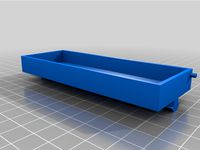
Box for Anet ET4
...box for anet et4
thingiverse
this is a simple box for tool of anet et4
thingiverse
free

Anet V1.0 Board Kühlung (80mm Lüfter) / Anet A8 by MadCre8
...anet v1.0 board kühlung (80mm lüfter) / anet a8 by madcre8
thingiverse
anet v1.0 board kühlung (80mm lüfter) / anet a8
Heat
3d_export
$5
heat
...heat
3dexport
heat tool
3ddd
$1
electric heating
...electric heating
3ddd
обогреватель
electric heating
3d_export
$6
The heating module
...any questions also you can email to me. designed with solidworks 2017, render with keyshot **************************************
turbosquid
$2
Heating Radiator
...
royalty free 3d model heating radiator for download as blend on turbosquid: 3d models for games, architecture, videos. (1561908)
3d_export
$35
heating instalation with heat pump and solar system
...el , please contact me. before buying a model, you can try to download one of my free models and testing. thank you for watching.
turbosquid
$29
Heating Mantle
... available on turbo squid, the world's leading provider of digital 3d models for visualization, films, television, and games.
turbosquid
$25
Heating Radiator
... available on turbo squid, the world's leading provider of digital 3d models for visualization, films, television, and games.
turbosquid
$20
AT_airship_control_stand_(heated)
... available on turbo squid, the world's leading provider of digital 3d models for visualization, films, television, and games.
turbosquid
$20
AT_airship_(heated)
... available on turbo squid, the world's leading provider of digital 3d models for visualization, films, television, and games.
turbosquid
$10
Heating radiator
... available on turbo squid, the world's leading provider of digital 3d models for visualization, films, television, and games.
Double
3ddd
free
Double
...double
3ddd
double , sicis
диван double от итальянской фабрики sicis next art
3d_ocean
$5

double stairs
...double stairs
3docean
double stairs
double stairs
3d_export
$5

double handle
...double handle
3dexport
double handle
3d_export
$5
double fastener
...double fastener
3dexport
double fastener
3ddd
$1
double bed
...double bed
3ddd
двуспальная
double bed
design_connected
free
Chair Double
...chair double
designconnected
free 3d model of chair double
3ddd
$1

Double Leaves
...double leaves
3ddd
double leaves
кресло китайской фабрики double leaves. vray, 3dmax 2013, гамма 2.2, текстуры в комплекте.
3ddd
free
Люстра Double
...люстра double
3ddd
double , david chipperfield
2004
размеры в архиве
3d_export
free

couch - double
...couch - double
3dexport
couch double with texture and .psd files for personal customization
3d_export
$10
double layer double speed chain
...d chain
3dexport
double layer speed chain (design very detailed) 3d model drawing model file reference using solidworks software
Bed
3ddd
$1
bed
...bed
3ddd
bed , постельное белье
bed
3ddd
$1
bed
...bed
3ddd
bed , постельное белье
bed
3ddd
$1
bed
...bed
3ddd
bed , постельное белье
bed
3ddd
$1
bed
...bed
3ddd
bed , постельное белье
bed
3ddd
$1
bed
...bed
3ddd
bed , постельное белье
bed
3ddd
$1

bed
...bed
3ddd
bed , постельное белье
bed
3ddd
free
bed
...bed
3ddd
bed , постельное белье
bed
3ddd
free
bed
...bed
3ddd
bed , постельное белье
bed
3ddd
$1
Bed
...bed
3ddd
bed , постельное белье , постель
bed
3d_export
$7
bed adairs bed
...rs bed
3dexport
bed adairs bed in modern style. if you want a smoother surface, please turn on turbosmooth in the modifier list.