Thingiverse
Anet A8 Controller's Microprocessor Replacement by chkmailroot
by Thingiverse
Last crawled date: 4 years, 7 months ago
Problems:
When I tried to upgrade the Anet A8 printer, I forgot to turn off the power supply and make the main controller chip damaged.
Solved:
Replace the chip and re-flash it.
Steps:
1st:
Solder out the damaged chip and replace it. Take out your power supply, it will be used to power your controller board when re-flash the firmware.
2nd:
If you already have an AVR ISP programmer, so skip this step.
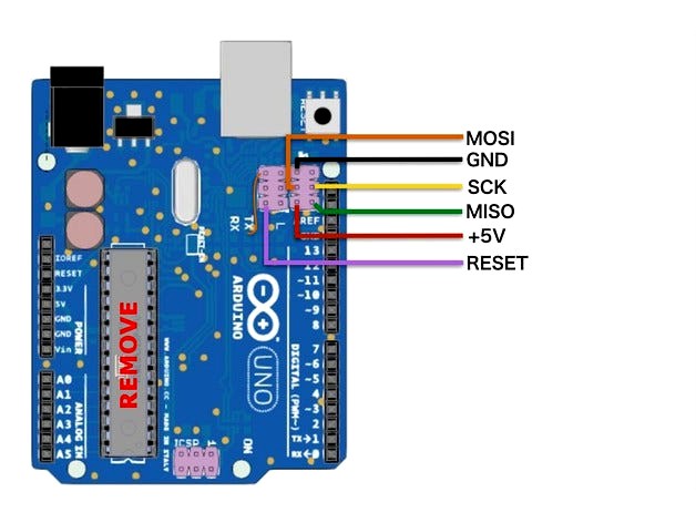
If you have an Arduino around, follow this link: http://make.kosakalab.com/make/electronic-work/avrisp-mk2/uno-r3_avrisp-mk2_en/
And if you don't have any ISP programmer or Arduino board, skip all of this post. :v or find one.
3rd:
Install AVR Studio. Then open Tool>Device Programming. Plug in ISP programmer that you have from 1st step. Connect ISP connect pins from ISP programmer to Controller board. Pinout in the above picture.
Programming parameters:
Fuse: 0xFD;0xDA;0xD6 (from up to down in programming fuse tab, VERY IMPORTANCE!!!)
Memory: Find the attached files.
MY MISTAKE:
I've flashed wrong fuse bytes, the AVR Atmega1284P chip cannot be recognized by ISP programmer. I must supply a clock source to XTAL1 pin of chip while re-flash the fuse byte. Pls cmt if you had this problem!
Finish! Goodluck
If have any problem, pls cmt!
When I tried to upgrade the Anet A8 printer, I forgot to turn off the power supply and make the main controller chip damaged.
Solved:
Replace the chip and re-flash it.
Steps:
1st:
Solder out the damaged chip and replace it. Take out your power supply, it will be used to power your controller board when re-flash the firmware.
2nd:
If you already have an AVR ISP programmer, so skip this step.
If you have an Arduino around, follow this link: http://make.kosakalab.com/make/electronic-work/avrisp-mk2/uno-r3_avrisp-mk2_en/
And if you don't have any ISP programmer or Arduino board, skip all of this post. :v or find one.
3rd:
Install AVR Studio. Then open Tool>Device Programming. Plug in ISP programmer that you have from 1st step. Connect ISP connect pins from ISP programmer to Controller board. Pinout in the above picture.
Programming parameters:
Fuse: 0xFD;0xDA;0xD6 (from up to down in programming fuse tab, VERY IMPORTANCE!!!)
Memory: Find the attached files.
MY MISTAKE:
I've flashed wrong fuse bytes, the AVR Atmega1284P chip cannot be recognized by ISP programmer. I must supply a clock source to XTAL1 pin of chip while re-flash the fuse byte. Pls cmt if you had this problem!
Finish! Goodluck
If have any problem, pls cmt!