Thingiverse
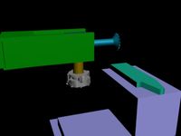
Anet A8 CNC Flex Shaft Mount by 3D_Pressure
by Thingiverse
Last crawled date: 3 years, 1 month ago
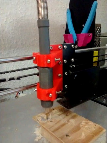
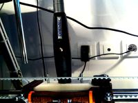
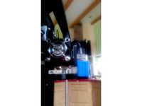
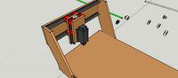
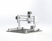
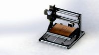
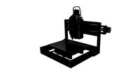
A mount to convert you Anet A8 to a light duty CNC Router.
What parts do you need for this conversion?
An Anet A8
Rotary Tool including Flex Shaft
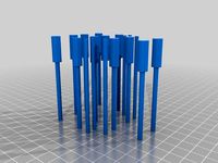
Mill Bits (Update: I changed to these Mill Bits which work better).
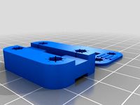
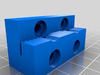
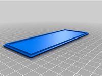
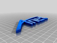
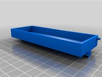
This Mount (three parts, each printed once)
four M3 Screws and Nuts
How do you mount this holder?
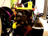
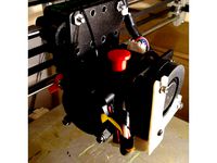
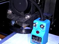
You'll need to remove the complete hotend from your printer. Just unscrew the the mount screw below the carriage, loosen the nut on the heat break, and slide it out. You also want to remove the cooling fan, just unscrew the two screws holding it on the carriage. You don't need to unplug the hotend, as your printer might complain if you do.
Clamp the end of the flex shaft into the holder, using the M3 screws and nuts and the printed parts.
Now install the holder onto the x-carriage. Remove the six screws on the left half of the carriage, put the holder in its position and use the screws to fix it there. Be sure to already have the end of the flex shaft clamped to the holder before installing the holder on the carriage.
How do I slice parts for CNC machining?
Obviously we are not going to slice parts, but calculating a toolpath instead. In the end both will give us .gcode files that our printer can process. I am using Fusion 360 to create my gcode files, there is a CAM tab dedicated to do so. This requires a postprocessor, thanks to Tech2C for sharing this one that works just fine for my Anet A8. You'll find a lot of tutorials on how to create a toolpath within Fusion 360, so I won't cover it here in detail. If you got any questions, feel free to ask them.
Be sure to set the horizontal movement speed and the ramp step size to resonable low numbers, as your printers frame is not as stiff as a dedicated CNC Router. I've been using 5mm/s (which is obviously way slower than what you are used to while printing!) and a "layer depth" of 0.5mm. You can easily enforce using small depth steps by telling fusion that the length of the cutting blade of your tool is e.g. only 1mm.
Notes about the acual milling process
Put something in between the material you are procesing and your print bed. You don't want to mill your print bed away, do you? I've been clamping the wood I wanted to process above a 1cm plank to protect my print bed.
I've only been testing wood so far, milling plastic should be fine, too. I can't tell whether milling of aluminium is possible, but I'd not count on it. I'll be trying to create a PCB, and let you know how it worked out.
Do a dry run before starting your first milling task.
Milling is quite noisy. And it also produces loads of wood dust, be prepared to handle it ;-)
Is it possible to use another rotary tool?
Sure, you may use any dremel you got your hands on. I like having the flex shaft, as it will reduce the weight on the carriage. If you need the clamps having a different size (for this shaft I needed Ø20mm on the bottom, and Ø15mm on the top clamp) just leave me a note, I can fairly easy change their sizes.
This tutorial shows a conversion using another mount and printer, but it may help you in converting your Anet A8, too.
Any kind of feedback is, as always, very welcome.
What parts do you need for this conversion?
An Anet A8
Rotary Tool including Flex Shaft
Mill Bits (Update: I changed to these Mill Bits which work better).
This Mount (three parts, each printed once)
four M3 Screws and Nuts
How do you mount this holder?
You'll need to remove the complete hotend from your printer. Just unscrew the the mount screw below the carriage, loosen the nut on the heat break, and slide it out. You also want to remove the cooling fan, just unscrew the two screws holding it on the carriage. You don't need to unplug the hotend, as your printer might complain if you do.
Clamp the end of the flex shaft into the holder, using the M3 screws and nuts and the printed parts.
Now install the holder onto the x-carriage. Remove the six screws on the left half of the carriage, put the holder in its position and use the screws to fix it there. Be sure to already have the end of the flex shaft clamped to the holder before installing the holder on the carriage.
How do I slice parts for CNC machining?
Obviously we are not going to slice parts, but calculating a toolpath instead. In the end both will give us .gcode files that our printer can process. I am using Fusion 360 to create my gcode files, there is a CAM tab dedicated to do so. This requires a postprocessor, thanks to Tech2C for sharing this one that works just fine for my Anet A8. You'll find a lot of tutorials on how to create a toolpath within Fusion 360, so I won't cover it here in detail. If you got any questions, feel free to ask them.
Be sure to set the horizontal movement speed and the ramp step size to resonable low numbers, as your printers frame is not as stiff as a dedicated CNC Router. I've been using 5mm/s (which is obviously way slower than what you are used to while printing!) and a "layer depth" of 0.5mm. You can easily enforce using small depth steps by telling fusion that the length of the cutting blade of your tool is e.g. only 1mm.
Notes about the acual milling process
Put something in between the material you are procesing and your print bed. You don't want to mill your print bed away, do you? I've been clamping the wood I wanted to process above a 1cm plank to protect my print bed.
I've only been testing wood so far, milling plastic should be fine, too. I can't tell whether milling of aluminium is possible, but I'd not count on it. I'll be trying to create a PCB, and let you know how it worked out.
Do a dry run before starting your first milling task.
Milling is quite noisy. And it also produces loads of wood dust, be prepared to handle it ;-)
Is it possible to use another rotary tool?
Sure, you may use any dremel you got your hands on. I like having the flex shaft, as it will reduce the weight on the carriage. If you need the clamps having a different size (for this shaft I needed Ø20mm on the bottom, and Ø15mm on the top clamp) just leave me a note, I can fairly easy change their sizes.
This tutorial shows a conversion using another mount and printer, but it may help you in converting your Anet A8, too.
Any kind of feedback is, as always, very welcome.
Similar models
thingiverse
free
Anet A8 Mainboard Fanholder by zumili
...x20mm screws or 3x m3x20mm and 3x m3x12mm screws
and 6x m3 hexnuts
and some screws of your choice to mount the fan to the holder.
thingiverse
free
Anet A8 Quick-Change Print Head by Generic_Designs
...ws i used are american #6 machine screws and nuts.
the bearing bracket, belt clamp and belt tensioners are for the corexy design.
thingiverse
free
Template holes for Anet A8 Carriage by jeff38100
...to create your anet a8 carriage ?
you need this template to drilling your part.
note :
set z to 4mm to keep the original screw.
thingiverse
free
Dremel Flex Shaft QuickFix Mount by jbr
...iage).
the "quickfix" part can also be used to attach any standard m4 50mm extruder on a quickfix dedicated carriage.
thingiverse
free

Tweaks for Quick Swap Mounting System for Anet A8 3D Printers by Dependable
...s://www.thingiverse.com/thing:2750693.
also feel free to check out my untested prints: https://www.thingiverse.com/thing:3149150
thingiverse
free

Anet A6/A8 Threaded Frame Mount/Clamp, Upgrade by Area51
...solid base plate. the plate can be plywood or similar most other solutions i found is either too big,...
thingiverse
free

Anet A8 Fan Holder by Nefalas
...ng the two existing screws.
this is a tight fit, which is what i wanted. you may need to enlarge it by 1 or 2%.
printed using pla
thingiverse
free

120mm Fan holder for Anet A8 power supply by designrex
...e on grabcad if you need the original file.
grabcad url: https://grabcad.com/library/120-mm-fan-holder-for-anet-a8-printer-psu-1
thingiverse
free
Belt Mount for ANET A8 by Swift2568
...dle so that it's clamped against the aluminum h plate.
i am not releasing the openscad file because it's a flipping mess.
thingiverse
free

Anet A8 titan bowden mount (ender 3 like)
....
it is basically the same idea as the ender 3 .
you need 4 screws m3x25 to mount the part to the carriage & x-stepper motor.
Flex
3ddd
$1

Flex
...flex
3ddd
flex , конференц-зал
кресло для переговоров
3ddd
$1

Flex — I Laccati
... i laccati
3ddd
flex , дверь
двери межкомнатные, окрашенные. flex, коллекция «i laccati»
3ddd
free
Flex Seating 6032
... конференц-зал , flex
кресло модульное, модель flex seating 6032
3ddd
free
TechnoGym Flex Posterior
... flex , тренажер
3ds max 2012 (v-ray) + fbx
technogym flex posterior
3ddd
$1
Банкетка Flex Team
... , flex team
http://www.abitant.com/products/banketka-flex-team-2014-kilt-pouf
3ddd
free
FLEX , I Laccati
...cati
3ddd
flex , i laccati
flex , i laccati
модель p 14 q stucco fiorentino decoro gigli
3ddd
$1

Metal lux / FLEX
...metal lux / flex
3ddd
metal lux
люстра metal lux flex.
turbosquid
$11
Stool Flex
...ty free 3d model stool flex for download as max, obj, and fbx on turbosquid: 3d models for games, architecture, videos. (1673813)
3ddd
$1

Flex by Skandiform
...flex by skandiform
3ddd
skandiform , стул
enjoy
turbosquid
$7

Flex Chair
... available on turbo squid, the world's leading provider of digital 3d models for visualization, films, television, and games.
A8
turbosquid
$47

Car A8
...
turbosquid
royalty free 3d model car a8 for download as max on turbosquid: 3d models for games, architecture, videos. (1196060)
turbosquid
$50

Audi A8
...yalty free 3d model audi a8 for download as 3dm, obj, and fbx on turbosquid: 3d models for games, architecture, videos. (1580187)
turbosquid
$15

Audi A8
...lty free 3d model audi a8 for download as obj, fbx, and blend on turbosquid: 3d models for games, architecture, videos. (1387519)
turbosquid
$500

Audi A8
... available on turbo squid, the world's leading provider of digital 3d models for visualization, films, television, and games.
3d_export
$5

Audi A8 3D Model
...audi a8 3d model
3dexport
audi a8 cars car
audi a8 3d model ma 20351 3dexport
3d_export
$5

Audi A8 3D Model
...audi a8 3d model
3dexport
3d model of audi a8
audi a8 3d model badyaka 12136 3dexport
3d_ocean
$89

Audi A8 2010
...usiness car car class class f f german german luxury luxury s s s8 s8 sedan sedan vehicle vehicle
new audi a8 2010 detaled model.
turbosquid
$39

A8 2018
...a8 2018 for download as 3ds, obj, wrl, c4d, fbx, dae, and stl on turbosquid: 3d models for games, architecture, videos. (1345349)
turbosquid
free

audi a8 l
...rbosquid
royalty free 3d model audi a8 l for download as obj on turbosquid: 3d models for games, architecture, videos. (1663016)
3d_ocean
$45

Audi A8 restyled
...our door vehicle was created in blender3d 2.62.realistic renderings were created with yafaray 0.1.2 realistic plugin.rendering...
Anet
thingiverse
free

Anet by derbodesign
...anet by derbodesign
thingiverse
logo anet
thingiverse
free
Anet e10 , Anet v1.0 by jonathan_943D
...anet e10 , anet v1.0 by jonathan_943d
thingiverse
soporte de ventilador de 80mm, para controladora anet v1.0
thingiverse
free
Anet A8 Anet AM8 Y belt holder
...anet a8 anet am8 y belt holder
thingiverse
anet a8 anet am8 y belt holder
thingiverse
free
Anet A8 Probe Bracket for anet sensor by chelrix
...anet a8 probe bracket for anet sensor by chelrix
thingiverse
anet a8 probe bracket for anet official sensor and marlin firmware
thingiverse
free
Anet logo by JUST3D_PRNTNG
...anet logo by just3d_prntng
thingiverse
anet logo
thingiverse
free
Fan nozzle for Anet A8 with original Anet levelsensor by peteruhlmann
...et levelsensor by peteruhlmann
thingiverse
here is an improved fan nozzle for the anet a8 with original level sensor from anet.
thingiverse
free
Anet Et4 Box
...anet et4 box
thingiverse
tool box for anet et4
thingiverse
free
Anet Logo by Superflex_Plastic_Fantastic
...anet logo by superflex_plastic_fantastic
thingiverse
anet logo to incorporate into designs.
thingiverse
free
Box for Anet ET4
...box for anet et4
thingiverse
this is a simple box for tool of anet et4
thingiverse
free

Anet V1.0 Board Kühlung (80mm Lüfter) / Anet A8 by MadCre8
...anet v1.0 board kühlung (80mm lüfter) / anet a8 by madcre8
thingiverse
anet v1.0 board kühlung (80mm lüfter) / anet a8
Pressure
3d_export
$5

pressure gauge
...pressure gauge
3dexport
pressure gauge
3d_export
$40

Pressure Vessel
...pressure vessel
3dexport
pressure vessel assembly render 3d modelling design
3d_export
$5
Pressure cooker
...pressure cooker
3dexport
simple low-poly pressure cooker model. not removable parts.
3d_export
$5

protected pressure gauge
...protected pressure gauge
3dexport
protected pressure gauge
turbosquid
$25
Vintage US Gauge Co Cluster, Pressure, Oil Pressure & Vacuum Fuel Pressure
...re for download as 3ds, dxf, obj, c4d, fbx, 3dm, dwg, and stl on turbosquid: 3d models for games, architecture, videos. (1367117)
turbosquid
$20

PRESSURIZATION FAN
...
royalty free 3d model pressurization fan for download as max on turbosquid: 3d models for games, architecture, videos. (1269534)
turbosquid
$20

Pressurization Pumps
...oyalty free 3d model pressurization pumps for download as max on turbosquid: 3d models for games, architecture, videos. (1270559)
turbosquid
$23

Pressure cooker
...ee 3d model pressure cooker for download as max, obj, and fbx on turbosquid: 3d models for games, architecture, videos. (1440991)
turbosquid
$25

pressure cooker
... available on turbo squid, the world's leading provider of digital 3d models for visualization, films, television, and games.
turbosquid
$3
Pressure Controller
... available on turbo squid, the world's leading provider of digital 3d models for visualization, films, television, and games.
Shaft
3d_export
$5
shaft handle
...shaft handle
3dexport
shaft handle
3d_export
$5

shaft bracket
...shaft bracket
3dexport
shaft bracket
turbosquid
$3

Shaft
... available on turbo squid, the world's leading provider of digital 3d models for visualization, films, television, and games.
turbosquid
$2

shaft
... available on turbo squid, the world's leading provider of digital 3d models for visualization, films, television, and games.
3d_export
free
crank shaft
...crank shaft
3dexport
crank shaft with piston with different materials
3d_export
$8
shaft bearing
...shaft bearing
3dexport
shaft bearing m10, m12,m16, m20 and m27
3d_export
$5
hexagonal shaft knob
...hexagonal shaft knob
3dexport
hexagonal shaft knob
3d_export
$5
shaft hand wheel
...shaft hand wheel
3dexport
shaft hand wheel
3d_export
$5
triangular shaft knob
...triangular shaft knob
3dexport
triangular shaft knob
3d_export
$5
octagonal shaft knob
...octagonal shaft knob
3dexport
octagonal shaft knob
Cnc
3d_export
$35
Cnc
...cnc
3dexport
the cnc machine is unfinished
3d_export
$10
cnc router
...cnc router
3dexport
prototipe cnc router
3d_export
$10
cnc machine
...cnc machine
3dexport
cnc machine model with individual model files with assembly
3d_export
$5
Cnc 3D Model
...cnc 3d model
3dexport
cnc
cnc 3d model csiszar 61289 3dexport
turbosquid
$10

cnc bedroom
...osquid
royalty free 3d model cnc bedroom for download as max on turbosquid: 3d models for games, architecture, videos. (1494981)
turbosquid
$9
cnc(wood)
...rbosquid
royalty free 3d model cnc(wood) for download as max on turbosquid: 3d models for games, architecture, videos. (1189189)
turbosquid
$1

CNC Frame
...rbosquid
royalty free 3d model cnc frame for download as stl on turbosquid: 3d models for games, architecture, videos. (1371706)
turbosquid
free
cnc table
...rbosquid
royalty free 3d model cnc table for download as max on turbosquid: 3d models for games, architecture, videos. (1500926)
turbosquid
$30
CNC Lathe
...
royalty free 3d model cnc lathe for download as max and obj on turbosquid: 3d models for games, architecture, videos. (1284634)
turbosquid
$25
CNC Machine
...
royalty free 3d model cnc machine for download as ma and fbx on turbosquid: 3d models for games, architecture, videos. (1307199)
Mount
3d_export
free

mounting bracket
...mounting plate is the portion of a hinge that attaches to the wood. mounting plates can be used indoors, cabinetry and furniture.
turbosquid
$2

MOUNTING
... available on turbo squid, the world's leading provider of digital 3d models for visualization, films, television, and games.
turbosquid
free

Mounts
... available on turbo squid, the world's leading provider of digital 3d models for visualization, films, television, and games.
turbosquid
free

Mount Fuji
...fuji
turbosquid
free 3d model mount fuji for download as obj on turbosquid: 3d models for games, architecture, videos. (1579977)
3d_export
$5

Headphone mount LR
...headphone mount lr
3dexport
headphone mount l+r
turbosquid
$39

Mount rainier
...quid
royalty free 3d model mount rainier for download as fbx on turbosquid: 3d models for games, architecture, videos. (1492586)
turbosquid
$5

pipe mounting
...quid
royalty free 3d model pipe mounting for download as obj on turbosquid: 3d models for games, architecture, videos. (1293744)
turbosquid
$3

Mounting Tires
...uid
royalty free 3d model mounting tires for download as fbx on turbosquid: 3d models for games, architecture, videos. (1708511)
3d_export
$5

Magnetic GoPro Mount
...pro mount
3dexport
cool magnetic mount for gopro. allows you to mount the camera on flat metal surfaces and get exclusive shots.
turbosquid
$5

Stone Mount
...ty free 3d model stone mount for download as ma, obj, and fbx on turbosquid: 3d models for games, architecture, videos. (1370306)