Thingiverse
Anet A8 3DTouch/BLTouch Auto Leveling Sensor Bracket by JMadison
by Thingiverse
Last crawled date: 3 years ago
Update 30-APR-2017: I added the config file that I’ve been giving to people who ask for my config file. The configuration enclosed is the original 5 button configuration file of SkynetV2.3.1 modified to support 3DTouch/BLTouch. Note that this is for SkynetV2.3.1.
--- End of update ---
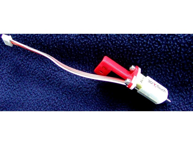
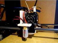
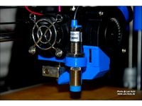
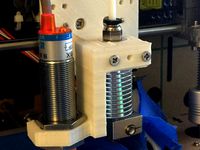
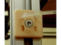
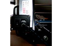
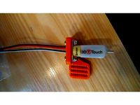
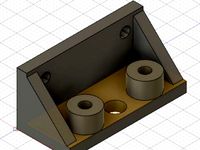
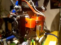
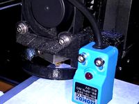
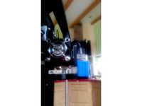
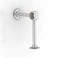
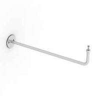
The 3DTouch/BLTouch sensor is a servo based sensor. Its main advantage is that it allows you to easily move between printing on glass or directly on the bed, without having to adjust auto leveling parameters. This sensor requires an additional pin that isn’t easily available on the Anet V1/Sanguinololu control board. To use this sensor on an Anet A8, you either have to move to a different board, modify the LCD cabling (see http://www.thingiverse.com/thing:2091529), or free up a pin on the Anet board by converting the display to I2C. See my design for freeing up a pin: http://www.thingiverse.com/thing:2098646 .
There are several 3DTouch brackets available on Thingiverse. Most won’t fit the Anet A8. The one that I found that would probably fit (http://www.thingiverse.com/thing:2084025 ) moves the sensor so that it’s almost in line with the fan, and it’s right next to the extruder cooling fins. This limits the bed area available to the probe in the Y direction. My design limits the X direction, but less than the limitation of the design that limits the Y direction.
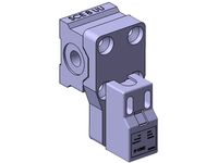
My design will only work on Anet A8s that have the same hole pattern on the extruder carriage as mine. This is a very tight fit. It should not touch anything and is greater than the manufacturer's minimum suggested distance of 15mm from the hot end/nozzle.
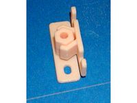
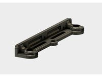
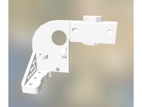
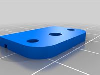
Prints: SensorBracket.stl, AlignmentSpacer.stl
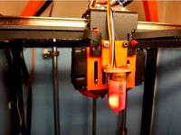
I printed both at 100% fill, 0.1mm, support “Touching Bed". I’m not a print settings expert, but I figured the bracket needs to be as rigid as possible. The alignment spacer is the distance from the base of the sensor to the bed when the nozzle is a paper thickness above the bed. The spacer is only as precise as your printer. Mine was dead on (today). It should measure 8.3mm on a good day.
Mount the sensor on the bracket before attaching the bracket to the extruder carriage.
Use Repetier-Host, Cura, etc., to place the nozzle the thickness of a sheet of paper off the bed. Use the alignment widget to set the height of the sensor above the bed.
Some of the Marlin/SkynetV2.3.1 Configuration.h settings: (the others you can get from the manufacturer’s documentation)
I determined these two offsets using the grid file "Coords mm.pdf"
define X_PROBE_OFFSET_FROM_EXTRUDER 59 // X offset: -left +right [of the nozzle]
define Y_PROBE_OFFSET_FROM_EXTRUDER 14 // Y offset: -front +behind [the nozzle]
The Z_PROBE_OFFSET_FROM_EXTRUDER setting should be set based on your actual results you measure during setup.
define LEFT_PROBE_BED_POSITION 15
define RIGHT_PROBE_BED_POSITION 195
define BACK_PROBE_BED_POSITION 205
define FRONT_PROBE_BED_POSITION 25
If you use a non-standard servo pin you’ll need to define SERVO0_PIN. In my case it’s 27.
define SERVO0_PIN 27
DO NOT attempt to do an Auto Home after your very first upload. Send one of the test gcodes to make sure you're connected.
M280 P0 S10 ; pushes the pin down
M280 P0 S90 ; pulls the pin up
M280 P0 S120 ; Self test – keeps going until you do pin up/down or release alarm
M280 P0 S160 ; Release alarm
Hardware: (2) M3 x 8, (2) M3 x 12, (4) M3 nuts
--- End of update ---
The 3DTouch/BLTouch sensor is a servo based sensor. Its main advantage is that it allows you to easily move between printing on glass or directly on the bed, without having to adjust auto leveling parameters. This sensor requires an additional pin that isn’t easily available on the Anet V1/Sanguinololu control board. To use this sensor on an Anet A8, you either have to move to a different board, modify the LCD cabling (see http://www.thingiverse.com/thing:2091529), or free up a pin on the Anet board by converting the display to I2C. See my design for freeing up a pin: http://www.thingiverse.com/thing:2098646 .
There are several 3DTouch brackets available on Thingiverse. Most won’t fit the Anet A8. The one that I found that would probably fit (http://www.thingiverse.com/thing:2084025 ) moves the sensor so that it’s almost in line with the fan, and it’s right next to the extruder cooling fins. This limits the bed area available to the probe in the Y direction. My design limits the X direction, but less than the limitation of the design that limits the Y direction.
My design will only work on Anet A8s that have the same hole pattern on the extruder carriage as mine. This is a very tight fit. It should not touch anything and is greater than the manufacturer's minimum suggested distance of 15mm from the hot end/nozzle.
Prints: SensorBracket.stl, AlignmentSpacer.stl
I printed both at 100% fill, 0.1mm, support “Touching Bed". I’m not a print settings expert, but I figured the bracket needs to be as rigid as possible. The alignment spacer is the distance from the base of the sensor to the bed when the nozzle is a paper thickness above the bed. The spacer is only as precise as your printer. Mine was dead on (today). It should measure 8.3mm on a good day.
Mount the sensor on the bracket before attaching the bracket to the extruder carriage.
Use Repetier-Host, Cura, etc., to place the nozzle the thickness of a sheet of paper off the bed. Use the alignment widget to set the height of the sensor above the bed.
Some of the Marlin/SkynetV2.3.1 Configuration.h settings: (the others you can get from the manufacturer’s documentation)
I determined these two offsets using the grid file "Coords mm.pdf"
define X_PROBE_OFFSET_FROM_EXTRUDER 59 // X offset: -left +right [of the nozzle]
define Y_PROBE_OFFSET_FROM_EXTRUDER 14 // Y offset: -front +behind [the nozzle]
The Z_PROBE_OFFSET_FROM_EXTRUDER setting should be set based on your actual results you measure during setup.
define LEFT_PROBE_BED_POSITION 15
define RIGHT_PROBE_BED_POSITION 195
define BACK_PROBE_BED_POSITION 205
define FRONT_PROBE_BED_POSITION 25
If you use a non-standard servo pin you’ll need to define SERVO0_PIN. In my case it’s 27.
define SERVO0_PIN 27
DO NOT attempt to do an Auto Home after your very first upload. Send one of the test gcodes to make sure you're connected.
M280 P0 S10 ; pushes the pin down
M280 P0 S90 ; pulls the pin up
M280 P0 S120 ; Self test – keeps going until you do pin up/down or release alarm
M280 P0 S160 ; Release alarm
Hardware: (2) M3 x 8, (2) M3 x 12, (4) M3 nuts
Similar models
thingiverse
free
Anet A6 BLTouch/3DTouch mount (front) by thvranken
...isplay or with command m851) and saved to the eeprom (using the display or with command m500), in my case, this was around -2 mm.
thingiverse
free

Anet A8 3DTouch/BLTouch Auto Leveling Sensor Bracket by tobicothon
...thingiverse
mount this bracket on right bearing (bottom screws).
no need to change the screws
offset on marlin :
x = +58
y= +10
thingiverse
free

Anet A8 Moving Fan Bracket by twistedfab13
... 220
define x_min_pos -33
define y_max_pos 220
define y_min_pos -10
define z_max_pos 240
define z_min_pos 0
thingiverse
free

3D touch Black Anet A8 Left_Mount by zerone82
...ne z_min_endstop_inverting false
#define z_min_probe_endstop_inverting false
comment
//#define probe_manually
wiring as per image
thingiverse
free
Sensor Mount for Anet A8 by mulger
...0 // y offset: -front +behind [the nozzle]
//#define z_probe_offset_from_extruder 0 // z offset: -below +above [the nozzle]
thingiverse
free

Anet A8 Front Fan Sensor Mount 18 mm by buzzkc
...://www.thingiverse.com/thing:2506274
the wiring schematic and parts list for my sensor: https://www.thingiverse.com/thing:2758533
thingiverse
free

Back holder for Auto Level Anet by PgSerbia
...of the nozzle]
define y_probe_offset_from_extruder 63 // y offset: -front +behind [the nozzle]
define front_probe_bed_position 55
thingiverse
free

Anet A8 BLTouch Holder by jvyoralek
...e-homing
#define z_safe_homing
define servo
#define num_servos 1
if you spot any issues with item please let me know in comments.
thingiverse
free
Anet A8 Sensor Bracket 12mm and 18mm by Leo_N
...not sensor related but the z homing speed was too fast for my taste. to have it move slower use:
define homing_feedrate_z (4*60)
thingiverse
free
Anet A8 18mm Inductive sensor Bracket for Bowden carriage by joshhmann
...these settings.
define x_probe_offset_from_extruder -15//-25 //-21
define y_probe_offset_from_extruder -5//-29 //-43
Jmadison
thingiverse
free
2020 Extrusion Cable Clip by JMadison
...trusion cable clip by jmadison
thingiverse
simple cable clip used to keep cables in place when running through a 2020 extrusion.
thingiverse
free
Flat Cable Mounting Clip by JMadison
...clip by jmadison
thingiverse
used to secure two 10 conductor flat cables.
uses a single m3 flathead screw.
print without support
thingiverse
free
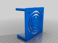
60mm Fan mount by JMadison
...an. no grill, only mounts to one side.
the fan mounting holes use 5mm fan screws. the 2 other mounting holes are for m3 screws.
thingiverse
free
DIRECTV Genie mini mounting bracket by JMadison
...genies and only the new model we got this year has this receptacle. the holes on the wall bracket are for #6/m3 flathead screws.
thingiverse
free
2020 Extrusion Cable Tie Mounts by JMadison
...hese are designed for cable ties less than 3mm wide.
the hole is for m3 flathead screws.
these should be printed without support.
thingiverse
free
UM2 Clone Power Switch Box by JMadison
...elf tapping flathead screws (other sizes will probably work)
snap in switch+receptacle: http://www.ebay.com/itm/like/221725745452
thingiverse
free
ABS Fume filter by JMadison
...strong fan to push air through the larger capacity version. i found a 67cfm fan (or so it claims). i'll see how it performs.
thingiverse
free
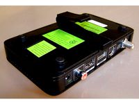
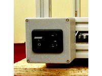
Anet A8 Switch Box by JMadison
...ck nuts (or regular and use locktite)
(2) m3 nuts
other:
i didn't remove the power supply to take the photos, i have a spare.
thingiverse
free
False Front Cabinet Clip by JMadison
...e project i’m building i needed 16 of them and i’m too cheap to buy them. this version is slightly less beefy than the original.
thingiverse
free
Ultimaker2 Clone Gantry Z Axis Top Remix by JMadison
... also makes it easier to ream the 12mm holes because the holes go all the way through.
the locking screws are m3 x 8 button head.
3Dtouch
thingiverse
free
3DTouch Holder by sopak
...3dtouch holder by sopak
thingiverse
universal 3dtouch and bltouch mount holes are 3mm with 5mm distance.
thingiverse
free
3DTouch binder by zull
...3dtouch binder by zull
thingiverse
platform for 3dtouch sensor from geeetech for geeetech i3 pro b with mk8 extruder
thingiverse
free
3DTouch Shield (Cover) by mardun
...e
shield/cover for 3dtouch to minimize led light. i tried to use other (mainly for bltouch) but they will not fit to my 3dtouch.
thingiverse
free
3DTouch model (STEP) by Leoliss
...retract - move needle in 3.8mm up. and yes, this is 3dtouch. bltouch have slightly different dimensions.
stl is just for preview.
thingiverse
free
GEEETech E3D v6 with 3DTouch by Minims
...geeetech e3d v6 with 3dtouch by minims
thingiverse
e3d v6 with 3dtouch for metal carriage
thingiverse
free
3dTouch probe model by deadcat
...e model by deadcat
thingiverse
this a fusion360 model of the 3dtouch to use when designing mounts. i have also included the stl.
thingiverse
free
3DTouch lock by markost
...he pin while printing and started breaking my prints and due potential damage to the sensor itself, i designed a pin lock for it.
thingiverse
free

BIQU B1 3DTouch mount by iNardex
...s not good for 3dtouch sensor.
designed for and tested with a 3dtouch v3.0.
i added the fusion360 project for any customizations.
thingiverse
free

Suport 3Dtouch BLTouch Graber Tec3d
...suport 3dtouch bltouch graber tec3d
thingiverse
suporte para fixar 3dtouch ou bltouch na extrusora graber i3 da tec3d.
thingiverse
free
3DTouch\BLTouch Holder for MiniTree T3 by zekeda1
...3dtouch\bltouch holder for minitree t3 by zekeda1
thingiverse
simple holder of 3dtouch\bltouch for minitree t3 3d printer.
Bltouch
thingiverse
free
Support bltouch by TonyJ
...support bltouch by tonyj
thingiverse
support bltouch
thingiverse
free
BLTOUCH for MICRON3DP by lamerhouse
...bltouch for micron3dp by lamerhouse
thingiverse
bltouch for micron3dp
thingiverse
free
SapphirePro mount for Bltouch
...sapphirepro mount for bltouch
thingiverse
sapphirepro mount for bltouch
thingiverse
free
ender6 BLtouch by chimaer
...ender6 bltouch by chimaer
thingiverse
ender6 bltouch
this is an external bracket
thingiverse
free
BLTouch KP3s by 1devilman1
...bltouch kp3s by 1devilman1
thingiverse
bltouch mount for kingroon kp3s
thingiverse
free
Bltouch support adjustable
...bltouch support adjustable
thingiverse
adjustable support for bltouch, p3steel.
thingiverse
free
BMG NEREUS BLTOUCH
...bmg nereus bltouch
thingiverse
petg
m3 screws and nuts for the bltouch
thingiverse
free

BLTouch Bracket by tidh666
...bltouch bracket by tidh666
thingiverse
serves to attach the bltouch sensor to the extruders
thingiverse
free
bltouch mount by wars
...bltouch mount by wars
thingiverse
reinforced bracket for bltouch cooperates with high_clearance_cr10_oem_fang_mod
thingiverse
free

BLTouch Holder by Jonthan06
...bltouch holder by jonthan06
thingiverse
support bltouch pour wanhao d12
A8
turbosquid
$47

Car A8
...
turbosquid
royalty free 3d model car a8 for download as max on turbosquid: 3d models for games, architecture, videos. (1196060)
turbosquid
$50
Audi A8
...yalty free 3d model audi a8 for download as 3dm, obj, and fbx on turbosquid: 3d models for games, architecture, videos. (1580187)
turbosquid
$15

Audi A8
...lty free 3d model audi a8 for download as obj, fbx, and blend on turbosquid: 3d models for games, architecture, videos. (1387519)
turbosquid
$500

Audi A8
... available on turbo squid, the world's leading provider of digital 3d models for visualization, films, television, and games.
3d_export
$5

Audi A8 3D Model
...audi a8 3d model
3dexport
audi a8 cars car
audi a8 3d model ma 20351 3dexport
3d_export
$5

Audi A8 3D Model
...audi a8 3d model
3dexport
3d model of audi a8
audi a8 3d model badyaka 12136 3dexport
3d_ocean
$89

Audi A8 2010
...usiness car car class class f f german german luxury luxury s s s8 s8 sedan sedan vehicle vehicle
new audi a8 2010 detaled model.
turbosquid
$39

A8 2018
...a8 2018 for download as 3ds, obj, wrl, c4d, fbx, dae, and stl on turbosquid: 3d models for games, architecture, videos. (1345349)
turbosquid
free

audi a8 l
...rbosquid
royalty free 3d model audi a8 l for download as obj on turbosquid: 3d models for games, architecture, videos. (1663016)
3d_ocean
$45

Audi A8 restyled
...our door vehicle was created in blender3d 2.62.realistic renderings were created with yafaray 0.1.2 realistic plugin.rendering...
Anet
thingiverse
free

Anet by derbodesign
...anet by derbodesign
thingiverse
logo anet
thingiverse
free
Anet e10 , Anet v1.0 by jonathan_943D
...anet e10 , anet v1.0 by jonathan_943d
thingiverse
soporte de ventilador de 80mm, para controladora anet v1.0
thingiverse
free
Anet A8 Anet AM8 Y belt holder
...anet a8 anet am8 y belt holder
thingiverse
anet a8 anet am8 y belt holder
thingiverse
free
Anet A8 Probe Bracket for anet sensor by chelrix
...anet a8 probe bracket for anet sensor by chelrix
thingiverse
anet a8 probe bracket for anet official sensor and marlin firmware
thingiverse
free
Anet logo by JUST3D_PRNTNG
...anet logo by just3d_prntng
thingiverse
anet logo
thingiverse
free
Fan nozzle for Anet A8 with original Anet levelsensor by peteruhlmann
...et levelsensor by peteruhlmann
thingiverse
here is an improved fan nozzle for the anet a8 with original level sensor from anet.
thingiverse
free
Anet Et4 Box
...anet et4 box
thingiverse
tool box for anet et4
thingiverse
free
Anet Logo by Superflex_Plastic_Fantastic
...anet logo by superflex_plastic_fantastic
thingiverse
anet logo to incorporate into designs.
thingiverse
free
Box for Anet ET4
...box for anet et4
thingiverse
this is a simple box for tool of anet et4
thingiverse
free

Anet V1.0 Board Kühlung (80mm Lüfter) / Anet A8 by MadCre8
...anet v1.0 board kühlung (80mm lüfter) / anet a8 by madcre8
thingiverse
anet v1.0 board kühlung (80mm lüfter) / anet a8
Sensor
3d_export
free

parking sensor
...parking sensor
3dexport
car parking sensor
turbosquid
$1
Sensor
... available on turbo squid, the world's leading provider of digital 3d models for visualization, films, television, and games.
3d_export
$5
Smoke sensor
...port
smoke sensor, can be an impressive element for your projects. easy to use, realistic image, low polygon, quality materials.
3d_export
$5
Air Quality Sensor v1
...air quality sensor v1
3dexport
air quality sensor v1
3d_export
$15
float sensor
...e up render. - all parts and materials are logically named. other formats ================= - collada (.dae) - autodesk fbx - obj
turbosquid
$26
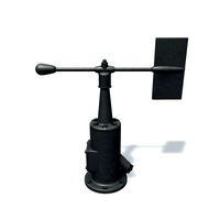
Wind sensor C
...free 3d model wind sensor c for download as 3ds, obj, and fbx on turbosquid: 3d models for games, architecture, videos. (1328943)
turbosquid
$26
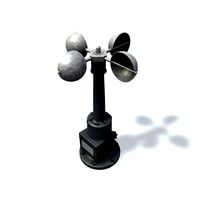
Wind sensor B
...free 3d model wind sensor b for download as 3ds, obj, and fbx on turbosquid: 3d models for games, architecture, videos. (1328168)
3d_export
$5
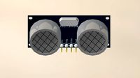
ultrasound sensor
...ivers convert ultrasound into electrical signals, and transceivers can both transmit and receive ultrasound. export in: -obj -fbx
3ddd
free
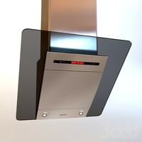
Вытяжка Shindo pallada sensor
... вытяжка
вытяжка shindo pallada sensor. в двух размерах - 600 и 900. текстуры в комплекте.
turbosquid
$52
Wind sensor A B C
...
royalty free 3d model wind sensor a b c for download as fbx on turbosquid: 3d models for games, architecture, videos. (1408406)
Auto
3d_export
$5

auto
...auto
3dexport
auto
3ddd
$1

auto
...auto
3ddd
max7
turbosquid
$69
AUTO
...to
turbosquid
royalty free 3d model auto for download as obj on turbosquid: 3d models for games, architecture, videos. (1453538)
3d_export
$10

Auto
...auto
3dexport
3d_export
free

auto
...auto
3dexport
3ddd
$1

Auto posters
...auto posters
3ddd
машина
auto posters
turbosquid
$50

auto
... available on turbo squid, the world's leading provider of digital 3d models for visualization, films, television, and games.
turbosquid
$28

Auto
... available on turbo squid, the world's leading provider of digital 3d models for visualization, films, television, and games.
turbosquid
$20
auto
... available on turbo squid, the world's leading provider of digital 3d models for visualization, films, television, and games.
turbosquid
$5
auto
... available on turbo squid, the world's leading provider of digital 3d models for visualization, films, television, and games.
Bracket
archibase_planet
free
Bracket
...bracket
archibase planet
bracket corbel holder
bracket 1 - 3d model (*.gsm+*.3ds) for interior 3d visualization.
archibase_planet
free
Bracket
...bracket
archibase planet
bracket corbel console
bracket 5 - 3d model (*.gsm+*.3ds) for interior 3d visualization.
archibase_planet
free
Bracket
...bracket
archibase planet
corbel holder bracket
bracket 6 - 3d model (*.gsm+*.3ds) for interior 3d visualization.
archibase_planet
free
Bracket
...bracket
archibase planet
bracket corbel console
bracket 8 - 3d model (*.gsm+*.3ds) for interior 3d visualization.
archibase_planet
free

Bracket
...bracket
archibase planet
bracket corbel holder
bracket n280911 - 3d model (*.gsm+*.3ds) for interior 3d visualization.
archibase_planet
free
Bracket
...bracket
archibase planet
holder corbel bracket
bracket 9 - 3d model (*.gsm+*.3ds) for interior 3d visualization.
archibase_planet
free
Bracket
...bracket
archibase planet
corbel holder bracket
bracket 10 - 3d model (*.gsm+*.3ds) for interior 3d visualization.
archibase_planet
free
Bracket
...bracket
archibase planet
corbel console bracket
bracket 11 - 3d model (*.gsm+*.3ds) for interior 3d visualization.
archibase_planet
free
Bracket
...bracket
archibase planet
holder console bracket
bracket 12 - 3d model (*.gsm+*.3ds) for interior 3d visualization.
archibase_planet
free
Bracket
...bracket
archibase planet
bracket corbel holder
bracket 13 - 3d model (*.gsm+*.3ds) for interior 3d visualization.
Leveling
design_connected
$11

Levels
...levels
designconnected
one nordic levels computer generated 3d model. designed by form us with love.
design_connected
$7
Level
...level
designconnected
zanotta level shelves and storage computer generated 3d model. designed by arik levy.
turbosquid
$29
level
...ty free 3d model level for download as 3ds, obj, c4d, and fbx on turbosquid: 3d models for games, architecture, videos. (1272856)
turbosquid
$1
level
... available on turbo squid, the world's leading provider of digital 3d models for visualization, films, television, and games.
3d_export
$5

Mario level
...mario level
3dexport
mario level low quality for fun videos
3ddd
$1
LEVELS OF DISCOVERY
...етская мебель "levels of discovery". rab10003 princess mini rocker
кресло-качалка (мини) "принцесса навсегда"
3d_export
$19
level design
...level design
3dexport
you can use this design (level design) in your own game.
turbosquid
$60
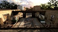
Desert level
...squid
royalty free 3d model desert level for download as fbx on turbosquid: 3d models for games, architecture, videos. (1208131)
turbosquid
$15
Transit Level
...quid
royalty free 3d model transit level for download as max on turbosquid: 3d models for games, architecture, videos. (1158112)
turbosquid
$14

Districts Level
...id
royalty free 3d model districts level for download as max on turbosquid: 3d models for games, architecture, videos. (1408410)