Thingiverse
AndreasL Dual z axis Smartrapcore ALU DjDemonD remix for 2020 with counterweight by DjDemonD
by Thingiverse
Last crawled date: 3 years ago
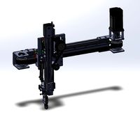
This is my version of the AndreasL alternative dual z axis for smartrapcore (http://www.thingiverse.com/thing:896556) but remixed for the aluminium 2020 frame version.
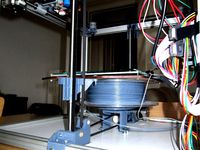
I have reorientated the axis so that it sits front to back not left to right to prevent it interfering with the corexy gantry at the sides. So all parts labelled R are Front and parts labelled L are Back. Please ensure your software endstop settings and define_manual_x_home and define_manual_y_home settings do not allow the head to move along the x direction and hit the top front bracket for this z axis.
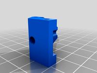
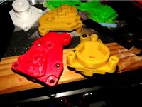
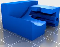
The parts I include here are the parts which needed to be modified for the alu version and should be fixed to the frame, plus a modified slider to make belt tensioning easier. Many of the non-printed parts you need are available from your old SCALU z axis.
BOM
Original SCALU parts:
2x 8mm smooth rods around 320mm
1x m8 x 20mm bolt
1x 608zz bearing
1x nema 17 motor
4 x m4 t-nuts + 4x m4 bolts
Additional parts
4x 608zz bearing
3 x m8 x20mm bolts
1 x m8 x 20mm axle/grub screw/shaft (see below)
4 x m4 t-nuts + 4x m4 bolts
4x m3 x 20mm + 4x m3 nylon lock nut
1.85m gt2 belt (I can highly recommend using steel reinforced)
Optional m3 x 20 bolt + 3mm bearing (or a larger bearing and a printed bushing)
The m8 axle (i.e. an m8 bolt with the head cut off, 20mm long. It goes in front of the motor to hold one of the bearings - it will help if you cut a slot in one end with a Dremel to screw it in with a flat bladed screwdriver).
If possible use a 0.9deg stepper instead for improved resolution, I am using a 42mm motor.
You might need another bearing if you put the additional pulley next to the motor to improve belt grip around the drive pulley but I am not sure its always necessary.
I have remixed one of the sliders with two belt clips. This means no need to join the belt with another part. (I am calling it the front one as its easier to tension the belt and attach it at the front than the back).
The remaining stl's which you might need you should obtain from the original design here: http://www.thingiverse.com/thing:896556
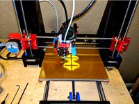
I have used the original plywood piece fixed to the sliders. A laser cut aluminium piece as shown in the original would be great but I wonder if it will be any lighter or stiffer in reality. I assembled everything making sure the smooth rods are aligned with the frame, The smooth rod should be 200mm from the frame on each side measured to the middle of the rod. I then strung the belts, placed the plywood on top of the sliders and marked where to drill the plywood, by pushing a little paint through the fixing holes with a fine point (these should be drilled out to 3mm). Then I attached it with m3 bolts and lock nuts.
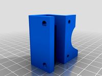
Ensure that the top brackets which hold the top bearings, are extremely level when installed, otherwise the belts "walk" across the pulleys and do not remain centralised. They do not come off the pulleys as there is insufficient space for them to do so, but belt wear would be considerably more if friction with the brackets is continually occurring.
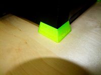
The springs at the bottom of the smooth rods I added to my original z axis and I used them instead of landing gear. I find this dual z axis descends on its own very gently when the motor is powered off and therefore I feel they are not needed. Without the springs you should be able to get around 170mm of z height - a big improvement!
Please be aware the original by AndreasL might change and therefore some geometry might be different. Please message me if you find an incompatibility and I will see about making changes here too. I might change things once I've had chance to extensively test it.
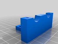
UPDATED 04/02/17- To improve the belt path for the front descending belt I have changed the z-slides. They now have one belt clip in a slightly different position. This means a straight belt path for the front descending belt, which should make the z axis more accurate when the nozzle is near to the bed. I cut away a small amount of my z-carriage to allow this belt access, but yours might not be in the way. I also wanted to stop the belts rubbing on the top brackets around the 608zz bearings, so I filed away the small flanges that centre the bearing in the top bracket and printed some m8 large washers to guide the belt.
UPDATED: Top brackets now attached which have been lightly reinforced, use them in exactly the same way as before. Much gratitude goes to AndreasL for the original design, this has performed admirably since I modified it and installed it.
UPDATED May 2016 - Have swapped to 16tooth drive pulley which has a default 100 steps/mm for 1.8 deg stepper or 200 steps/mm for 0.9 deg stepper. Slightly improved resolution but also a little more gearing to help the motor lift the axis.
Also when attaching the belts I found it very helpful to find two objects the same size, for example around 100mm long. Place them under the bed plywood, and rest the bed on them, then attach innermost front belt, then the back belt then the front one. This avoids the plywood tilting under unequal belt tension, and makes adjusting the build plate level easier once assembled.
UPDATE May 2016 - So someone suggested a counterweight, and since I've upgraded my machine to 300x200 the z carriage now weights in at 700g. So I designed a bearing holder to be mounted over the front lower bracket. Add an m8 bolt, two large washers and a 608zz bearing, then a short run of belt cable tied to the front-most belt and laid over the washer. You can then add weight to it just less than your z carriage/bed total assembly. I am using a 500g weight for a 700g carriage meaning the carriage is now effectively 200g. This now descends nicely without a harsh bump at the bottom and means I can lower the current on my z stepper motor.
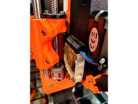
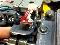
October 2016 - Decided to do away with the Z probe and replace it with a Z endstop. Came up with a add-on to the lower front Z axis bracket. This is designed for a mechanical endstop module board. Superglue or acetone weld the endstop bracket to the lower z axis front bracket attach the endstop. Bend the endstop lever upwards slightly.
Have something under the bed like landing gear or springs or similarr so that the bed stop just short under elastic tension of the endstop, that way when homing the firmware finds the endstop trigger point, and does not press it fully home as this will be less reproducible.
Another method to improve z endstop reproducibility when used in this way is to have home z (g28 z) before home all in your start gcode. That way if the bed is resting fully on the endstop ie past its trigger point the axis will lift and then rehome at the trigger point before homing x and y.
More details of how I configured the firmware etc.. can be found herehttp://forums.reprap.org/read.php?344,703348
Public files on Tinkercad if you want to copy then edit them:https://tinkercad.com/things/hr1XKGkmAnAhttps://tinkercad.com/things/aeBVa3ZfJGAhttps://tinkercad.com/things/d5LJ8QEVrpPhttps://tinkercad.com/things/9UOXC4BadERhttps://tinkercad.com/things/iFL1oCg6VIM
I have reorientated the axis so that it sits front to back not left to right to prevent it interfering with the corexy gantry at the sides. So all parts labelled R are Front and parts labelled L are Back. Please ensure your software endstop settings and define_manual_x_home and define_manual_y_home settings do not allow the head to move along the x direction and hit the top front bracket for this z axis.
The parts I include here are the parts which needed to be modified for the alu version and should be fixed to the frame, plus a modified slider to make belt tensioning easier. Many of the non-printed parts you need are available from your old SCALU z axis.
BOM
Original SCALU parts:
2x 8mm smooth rods around 320mm
1x m8 x 20mm bolt
1x 608zz bearing
1x nema 17 motor
4 x m4 t-nuts + 4x m4 bolts
Additional parts
4x 608zz bearing
3 x m8 x20mm bolts
1 x m8 x 20mm axle/grub screw/shaft (see below)
4 x m4 t-nuts + 4x m4 bolts
4x m3 x 20mm + 4x m3 nylon lock nut
1.85m gt2 belt (I can highly recommend using steel reinforced)
Optional m3 x 20 bolt + 3mm bearing (or a larger bearing and a printed bushing)
The m8 axle (i.e. an m8 bolt with the head cut off, 20mm long. It goes in front of the motor to hold one of the bearings - it will help if you cut a slot in one end with a Dremel to screw it in with a flat bladed screwdriver).
If possible use a 0.9deg stepper instead for improved resolution, I am using a 42mm motor.
You might need another bearing if you put the additional pulley next to the motor to improve belt grip around the drive pulley but I am not sure its always necessary.
I have remixed one of the sliders with two belt clips. This means no need to join the belt with another part. (I am calling it the front one as its easier to tension the belt and attach it at the front than the back).
The remaining stl's which you might need you should obtain from the original design here: http://www.thingiverse.com/thing:896556
I have used the original plywood piece fixed to the sliders. A laser cut aluminium piece as shown in the original would be great but I wonder if it will be any lighter or stiffer in reality. I assembled everything making sure the smooth rods are aligned with the frame, The smooth rod should be 200mm from the frame on each side measured to the middle of the rod. I then strung the belts, placed the plywood on top of the sliders and marked where to drill the plywood, by pushing a little paint through the fixing holes with a fine point (these should be drilled out to 3mm). Then I attached it with m3 bolts and lock nuts.
Ensure that the top brackets which hold the top bearings, are extremely level when installed, otherwise the belts "walk" across the pulleys and do not remain centralised. They do not come off the pulleys as there is insufficient space for them to do so, but belt wear would be considerably more if friction with the brackets is continually occurring.
The springs at the bottom of the smooth rods I added to my original z axis and I used them instead of landing gear. I find this dual z axis descends on its own very gently when the motor is powered off and therefore I feel they are not needed. Without the springs you should be able to get around 170mm of z height - a big improvement!
Please be aware the original by AndreasL might change and therefore some geometry might be different. Please message me if you find an incompatibility and I will see about making changes here too. I might change things once I've had chance to extensively test it.
UPDATED 04/02/17- To improve the belt path for the front descending belt I have changed the z-slides. They now have one belt clip in a slightly different position. This means a straight belt path for the front descending belt, which should make the z axis more accurate when the nozzle is near to the bed. I cut away a small amount of my z-carriage to allow this belt access, but yours might not be in the way. I also wanted to stop the belts rubbing on the top brackets around the 608zz bearings, so I filed away the small flanges that centre the bearing in the top bracket and printed some m8 large washers to guide the belt.
UPDATED: Top brackets now attached which have been lightly reinforced, use them in exactly the same way as before. Much gratitude goes to AndreasL for the original design, this has performed admirably since I modified it and installed it.
UPDATED May 2016 - Have swapped to 16tooth drive pulley which has a default 100 steps/mm for 1.8 deg stepper or 200 steps/mm for 0.9 deg stepper. Slightly improved resolution but also a little more gearing to help the motor lift the axis.
Also when attaching the belts I found it very helpful to find two objects the same size, for example around 100mm long. Place them under the bed plywood, and rest the bed on them, then attach innermost front belt, then the back belt then the front one. This avoids the plywood tilting under unequal belt tension, and makes adjusting the build plate level easier once assembled.
UPDATE May 2016 - So someone suggested a counterweight, and since I've upgraded my machine to 300x200 the z carriage now weights in at 700g. So I designed a bearing holder to be mounted over the front lower bracket. Add an m8 bolt, two large washers and a 608zz bearing, then a short run of belt cable tied to the front-most belt and laid over the washer. You can then add weight to it just less than your z carriage/bed total assembly. I am using a 500g weight for a 700g carriage meaning the carriage is now effectively 200g. This now descends nicely without a harsh bump at the bottom and means I can lower the current on my z stepper motor.
October 2016 - Decided to do away with the Z probe and replace it with a Z endstop. Came up with a add-on to the lower front Z axis bracket. This is designed for a mechanical endstop module board. Superglue or acetone weld the endstop bracket to the lower z axis front bracket attach the endstop. Bend the endstop lever upwards slightly.
Have something under the bed like landing gear or springs or similarr so that the bed stop just short under elastic tension of the endstop, that way when homing the firmware finds the endstop trigger point, and does not press it fully home as this will be less reproducible.
Another method to improve z endstop reproducibility when used in this way is to have home z (g28 z) before home all in your start gcode. That way if the bed is resting fully on the endstop ie past its trigger point the axis will lift and then rehome at the trigger point before homing x and y.
More details of how I configured the firmware etc.. can be found herehttp://forums.reprap.org/read.php?344,703348
Public files on Tinkercad if you want to copy then edit them:https://tinkercad.com/things/hr1XKGkmAnAhttps://tinkercad.com/things/aeBVa3ZfJGAhttps://tinkercad.com/things/d5LJ8QEVrpPhttps://tinkercad.com/things/9UOXC4BadERhttps://tinkercad.com/things/iFL1oCg6VIM
Similar models
thingiverse
free

Improved L for andreasL's alternative Z for SmartRapCore by Feoraz
... on the back, this eliminates the original coupler for the timing belt. (joint_couroie_corps.stl and joint_couroie_couvercle.stl)
thingiverse
free

FLSun i3 Factory Printable Parts Collection (linear rod and bearing version) by macelius
...xis belt tensioner (2 parts)
y-axis bed rail mounts
z-axis top corner brackets - 10mm tall
z-axis top corner brackets - 40mm tall
thingiverse
free

OB1.4 open beam single z motor by Pixhawk
...te made to lock bottom bearing in place. place on top of z_bottom_bearing.stl and bolt down. i'll upload a picture shortly.
thingiverse
free
Z motor mount for single engine Prusa I2 by lampoverde
...ley and belt.
attention in order to use the nema motor mounted on the z-axis must have the double tree "front and back"
thingiverse
free

X and Y-axis guides for MendelMax by Amplivibe
...xis guide i just place the bearings on the rod with some spacers in between. then click the guide on the 20mm aluminum extrusion.
thingiverse
free

Dual GT2 Belt Driven Z Axis for Hypercube by n9jcv
...or placement of pulleys (i just printed plastic washers not critical).
again i am 100% happy with the performance of the z now.
thingiverse
free
Y bearing bracket by Alekseev_D
...lastic pulley to another carrier (axle bearing to move down a bit.)
pros: a bearing 608, an increase in movement along the z axis
thingiverse
free
Vertical X Endstop bracket for Z couplers
... m2 screws.
to install, install the bracket first without the endstop on the pekciton x motor bracket. then screw in the endstop.
thingiverse
free
Anycubic I3 Z-Carriage upgrade by Deadsnale
...work well.
if you have any questions please let me know in the comments. if you print them and please let me know how they work.
thingiverse
free
3DCR Double accessories, X-axis v1.2 endstop holder by Prenta
...ofhttp://www.thingiverse.com/thing:201184
i put an overlenght bolt to the x idlers bearing, so the endstop reaches limit there.
Andreasl
thingiverse
free
Double Z adaptation kit for smartrapcore alu by andreasL
...for smartrapcore alu by andreasl
thingiverse
those parts will permit you to use my alternative z axis on your smartrapcore alu.
thingiverse
free

Smartrapcore cooler fan duct by andreasL
...0/04 : added a hole for a m3 screw to tight on the sensor , recentered the fan mounting holes, tightened the end of the air duct.
thingiverse
free
Improved L for andreasL's alternative Z for SmartRapCore by Feoraz
... on the back, this eliminates the original coupler for the timing belt. (joint_couroie_corps.stl and joint_couroie_couvercle.stl)
thingiverse
free

Axe Z pour smartrapCore d'andreasL version renforcée by Knou
... de matière
up_r : ajout de matière
pour le reste des pièces, ci-joint le dépot initial : http://www.thingiverse.com/thing:896556
thingiverse
free

Mechanical Z Endstop for DjDemonD/AndreasL Dual z axis smartrapcore alu by DjDemonD
...babystep z on the first print and used m206 to enter the home offset. (nb. if the nozzle was 1mm too high the m206 z would be 1.)
thingiverse
free

Gunstruder : Belt friction extruder Cold-end by andreasL
...se, lightly scale up the " quicklock" part !
bom and french forum : http://talk.smartfri.odns.fr/index.php?topic=794.0
thingiverse
free

Axe Z pour smartrapCore (alternative Z axis) by andreasL
...h the bigger hole.
step and solidworks files here :
https://www.dropbox.com/sh/1nty6k0aptx1sfa/aaan01kmu05veyh1qdxaok2_a?dl=0
thingiverse
free
Gunstruder : Parts for 3mm filament by Zapperke
...esteps: "222" 1.8 degree stepper 16th microstep thanks to andreasl for this great...
thingiverse
free
![[ SmartrapCore ] Support pour EndStopZ microswitch by Makoto_Doushite](/t/8618108.jpg)
[ SmartrapCore ] Support pour EndStopZ microswitch by Makoto_Doushite
...thingiverse support pour endstopz microswitch sur le systéme z d'andreasl s'utilise avec le design : axe z pour smartrapcore...
Djdemond
thingiverse
free
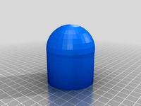
50mm Towball cover Hitch Cap by DjDemonD
...50mm towball cover hitch cap by djdemond
thingiverse
cover for 50mm towball.
thingiverse
free
Duet3D Smarteffector Nimble Mount DjDemonD Remix by DjDemonD
...ess sensitive. you also need to consider the orientation of the large nut to you heatsink when assembling the hotend into the se.
thingiverse
free

Brio Wooden Train Tunnel by DjDemonD
...valley etc.. multiple units can be joined to make a longer tunnel. 80mm diameter so even fairly large trains can make it through.
thingiverse
free

Bowden pushfit locking ring for clone titan and y-splitter by DjDemonD
...for clone titan and y-splitter by djdemond
thingiverse
locking clip for trianglelabs clone titan and y-splitter bowden fittings.
thingiverse
free
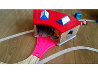
3-Way Approach for Brio Thomas Engine Shed by DjDemonD
...ond
thingiverse
i bought one of these engine sheds but didn't have the approach track which is a custom piece so i made one.
thingiverse
free

Precision Piezo - 27mm and 20mm Piezo Disc drill guide. by DjDemonD
... djdemond
thingiverse
drilling guide for piezo discs to centre your drill.
see youtube video here: https://youtu.be/ms1fd0v5z68
thingiverse
free
Mechanical Z Endstop for DjDemonD/AndreasL Dual z axis smartrapcore alu by DjDemonD
...babystep z on the first print and used m206 to enter the home offset. (nb. if the nozzle was 1mm too high the m206 z would be 1.)
thingiverse
free
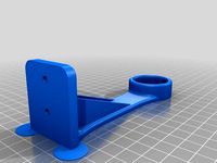
Paper Towel Holder Strengthened Remix by DjDemonD
...t to allow for the strengthening braces. since altering it, it works perfectly in fact i am even using some as spool holders too.
thingiverse
free
Sensor Test Rig by DjDemonD
...aver. i am not going to provide full build instructions, if you cannot figure out how to build it, should you be testing sensors?
thingiverse
free

Technics 1200 Turntable with spinning record by DjDemonD
... fits over a 5mm motor shaft and spins as my printer prints.
just bond it all together after assembly with superglue or acetone.
Smartrapcore
thingiverse
free

Smartrapcore 1.2.2 by caesarmaker
...smartrapcore 1.2.2 by caesarmaker
thingiverse
smartrapcore plastic parts
thingiverse
free
Smartrapcore 1.2.2 by caesarmaker
...smartrapcore 1.2.2 by caesarmaker
thingiverse
smartrapcore plastic parts
thingiverse
free

smartrapcore by tenij000
...smartrapcore by tenij000
thingiverse
endstop
thingiverse
free
![[ SmartrapCore ] by Makoto by Makoto_Doushite](/t/8617695.jpg)
[ SmartrapCore ] by Makoto by Makoto_Doushite
...ent bowden extruder with push fit pc6-m6 : https://www.thingiverse.com/thing:2691683 [ replaced because too weak for good print ]
thingiverse
free

Smartrapcore fanduct by yann44
...of bottom airflowhttps://cad.onshape.com/documents/4fea958d6bd043ae81cdb6af/w/8f126fa5f8144d13a14a42f9/e/2a8afe8ff3ce4d6fa22a4a8e
thingiverse
free

Adjustable Z Endstop for SmartrapCore by gsyan
...adjustable z endstop for smartrapcore by gsyan
thingiverse
use a micro switch as smartrapcore z endstop.
thingiverse
free

Adaptateur Volcano head SmartrapCore by ratcut
...adaptateur volcano head smartrapcore by ratcut
thingiverse
adapteur pour tête volcano sur smartrapcore
thingiverse
free
Foot for wood SmartrapCore by grami_fr
... wood smartrapcore.
it was a test to reduce vibration on the desk.
and it works....i think it's better with this litlle foot.
thingiverse
free

FilamentHolder for Smartrapcore ALU by sun121025
...21025
thingiverse
filamentholder for smartrapcore alu
20mmx20mm frame
cura 0.2mm layer height
20%
printer speed 50
take me 1h40m
thingiverse
free
Dual Hotend for Smartfriend Smartrapcore by Davemoon
...rapcore by davemoon
thingiverse
this is a dual hotend holder for my smartrapcore printer. it uses the original holes and screws.
Counterweight
design_connected
free

Counterweight Floor Lamp
...counterweight floor lamp
designconnected
free 3d model of counterweight floor lamp by stilnovo
3ddd
$1

RH Counterweight Task Table Lamp
... restoration hardware
http://www.restorationhardware.com/catalog/product/product.jsp?productid=prod60202
3ddd
$1

Restoration Hardware
...restoration hardware 3ddd restoration hardware restoration hardware | counterweight task floor...
3d_ocean
$39

Hawthorn Bridge
...it is a draw bridge that uses large cement counterweight to lift the span. the model was made in...
3ddd
free

Swing by Fambuena
...by nicola nerboni adjustable height pendant fixture with unique counterweight system available in black chrome or glossy white. the...
3d_export
$35
liebherr
...42 m, jib length from 9.5 to 17 m, counterweight - 12 tons.<br>format : 3ds fbx obj...
3ddd
$1
Delightfull SINATRA floorlamp
...sinatra floorlamp technical info materials: body: brass shade: aluminum counterweight steel weight: aprox. 12 kg | 26,5 lbs files:...
3ddd
$1
Pro-Ject Signature 10
...15,5 g suitable cartridge mass 4 - 10g, several counterweight included tonearm cable included pro-ject connect it 5p-c power...
3d_export
$5

Italian cuisine Valcucine Artematica New Logica
...door is easily opened and closed due to the counterweight<br>https://www.stels.ru/catalog/brand/valcucine/ ...
3d_export
$149

MT900 Tractor
...xsi soft image 2014/maya mb/blender 25 ambulance lights cabin counterweight driving controller engine exhaust pipe fenders with rear lights...
Alu
3ddd
free
LEDS-C4 Alu
...leds-c4 alu
3ddd
leds-c4
leds-c4 alu
3ddd
$1

Beluga Alu
...ный
светильник напольный 370*370*390 мм
материал : алюминий
e27 1 x 75w ipar / 14,5w led / 30w fbt
ip65
дизайн marck sadler
3ddd
$1

Зонт SHA ALU
...зонт sha alu
3ddd
зонт
http://www.royalbotania.com/products/sha-alu
3ddd
$1

Диван NATAL ALU SOFA
... угловой
диван natal alu sofa
производитель tribu
модель в размерах
текстуры в архиве
3d max 2014+obj
turbosquid
$2

Handle alu-lkw4
... available on turbo squid, the world's leading provider of digital 3d models for visualization, films, television, and games.
3ddd
$1
Vasco. Alu-zen
...a flat aluminium designer heated towel rails with rounded side profiles.
measure: 2000 x 525 mm.
file: max 2010, 2012; fbx; obj.
3ddd
$1

Coffee Table Spidernet Alu
... кофейный
кофейный столик coffee table spidernet alu
material:
алюминий
size:
0,34 x 0,89 x 0,89 m
weight:
17,75 кг
turbosquid
$5

Coffee Cup Alu Version
... available on turbo squid, the world's leading provider of digital 3d models for visualization, films, television, and games.
3ddd
$1
KARE / Network Alu
... банкетка , скамья
220 000 polys
сайт производителя:http://www.karedesign.de/
design_connected
$13

Alusion Lounge ALU 195 T.
...ignconnected
royal botania alusion lounge alu 195 t. seating objects computer generated 3d model. designed by kris van puyvelde.
Dual
turbosquid
free

Dual Pistols
...ls
turbosquid
free 3d model dual pistols for download as fbx on turbosquid: 3d models for games, architecture, videos. (1320360)
turbosquid
$2
Dual Axe
...urbosquid
royalty free 3d model dual axe for download as fbx on turbosquid: 3d models for games, architecture, videos. (1332372)
turbosquid
$10

Dual Lesaths
... available on turbo squid, the world's leading provider of digital 3d models for visualization, films, television, and games.
3ddd
$1
плитка Dual Bianco (Испания)
...й плитки venis dual (испания). технические качества: устойчивость к стирания, отличная геометрия, отсутствие проблем при укладке.
turbosquid
$35

Dual Mesh Fonts
...ree 3d model dual mesh fonts for download as ma, obj, and fbx on turbosquid: 3d models for games, architecture, videos. (1352989)
turbosquid
$29

Dual Flask with Bungs
...del dual flask with bungs for download as obj, fbx, and blend on turbosquid: 3d models for games, architecture, videos. (1210512)
turbosquid
$19
Dual Socket Plug
...3d model dual socket plug for download as obj, fbx, and blend on turbosquid: 3d models for games, architecture, videos. (1303912)
turbosquid
$13
Dual Adjustable Pulley
... available on turbo squid, the world's leading provider of digital 3d models for visualization, films, television, and games.
turbosquid
$10

Amoi N809 Dual
... available on turbo squid, the world's leading provider of digital 3d models for visualization, films, television, and games.
turbosquid
$5
Dual Turret Tank
... available on turbo squid, the world's leading provider of digital 3d models for visualization, films, television, and games.
Axis
3ddd
$1

Мария Axis
...
3ddd
кухня , классическая , axis
модель кухни.
3d_export
$22
Axis robot 6-axis robotic arm
...ing parts drawings, standard parts purchased parts list, can be produced directly according to the drawings, welcome to download!
3ddd
free

Versatile Axis
...ddd
nexus , плитка
http://bvtileandstone.com/ceramic-porcelain/versatile-axis/
3d_export
$19
robot 2 axis
...robot 2 axis
3dexport
robot 2 axis
turbosquid
$40
Axis R5F
... available on turbo squid, the world's leading provider of digital 3d models for visualization, films, television, and games.
turbosquid
$40
Axis S5F
... available on turbo squid, the world's leading provider of digital 3d models for visualization, films, television, and games.
turbosquid
$30

Axis Athlon
... available on turbo squid, the world's leading provider of digital 3d models for visualization, films, television, and games.
turbosquid
$10

Linear Axis
... available on turbo squid, the world's leading provider of digital 3d models for visualization, films, television, and games.
3d_export
$15

drawing axis
...drawing axis
3dexport
simple rendering of the scene file
3ddd
$1
versatile axis ARC
...versatile axis arc
3ddd
versatile , плитка
versatile axis arc red dot design award
2020
3d_export
$5

cyberpunk 2020
...cyberpunk 2020
3dexport
cyberpunk 2020
3d_export
$5
monster01 2020
...monster01 2020
3dexport
monster01 2020 dxf file rigged in mixamo.
3d_export
$129

explorer 2020
...explorer 2020
3dexport
3d_export
$5

mug 2020
...mug 2020
3dexport
3d_export
$15

3 rims 2020
...3 rims 2020
3dexport
new rims 2020 from inventor
turbosquid
$7

Keepsake of 2020
...ty free 3d model keepsake of 2020 for download as obj and stl on turbosquid: 3d models for games, architecture, videos. (1657350)
3d_export
$35

landrover 2020
...landrover 2020
3dexport
turbosquid
$15

Timeless 2020
...free 3d model timeless 2020 for download as max, obj, and fbx on turbosquid: 3d models for games, architecture, videos. (1433362)
turbosquid
$85

Q8 2020
... free 3d model audi q8 2020 for download as max, obj, and fbx on turbosquid: 3d models for games, architecture, videos. (1559582)
turbosquid
$59

Supra 2020
...ee 3d model supra 2020 for download as max, lwo, obj, and c4d on turbosquid: 3d models for games, architecture, videos. (1404492)
Z
3d_export
$5
nissan z
...nissan z
3dexport
nissan z
3ddd
$1

Vase Z
...vase z
3ddd
vase z
3ddd
$1
полотенцесушить Z
...полотенцесушить z
3ddd
полотенцесушитель
полотенцесушить z
design_connected
free

Z-Chair
...z-chair
designconnected
free 3d model of z-chair designed by karman, aleksei.
design_connected
$11

Z Lamp
...z lamp
designconnected
phillips z lamp computer generated 3d model. designed by kalff, louis.
3d_export
$5
Dragon balls z
...dragon balls z
3dexport
dragon ball z
turbosquid
$20

Fighter Z
...
turbosquid
royalty free 3d model fighter z for download as on turbosquid: 3d models for games, architecture, videos. (1292563)
turbosquid
$9

Pen Z
...pen z
turbosquid
free 3d model pen z for download as obj on turbosquid: 3d models for games, architecture, videos. (1686775)
turbosquid
free

z chair
...z chair
turbosquid
free 3d model z chair for download as max on turbosquid: 3d models for games, architecture, videos. (1410230)
turbosquid
$5

Letter Z
...urbosquid
royalty free 3d model letter z for download as max on turbosquid: 3d models for games, architecture, videos. (1408540)
Remix
turbosquid
$5
MODA Collection Remix Chair
... available on turbo squid, the world's leading provider of digital 3d models for visualization, films, television, and games.
3d_export
$12

remix yamaha rm1x
...remix yamaha rm1x
3dexport
geometry triangles 15.2k vertices 7.6k pbr no textures 1 materials 1 uv layers yes
3d_ocean
$5

Vray fabric Kvadrat remix green - tileable
...th vray and 3dsmax. high-resolution texture images (2000×2000 px) file included: shader vray 2.40 texture image 3ds max 2011 file
turbosquid
$20

Gerrit Rietveld 1938 Zig Zag Chair Remix
... available on turbo squid, the world's leading provider of digital 3d models for visualization, films, television, and games.
3d_export
$10

multicolored remix parametric table furniture
... fbx, obj, mtl, archive with textures. the model has no glitches. render and materials - vray . without using plugins. good use!
3ddd
$1
Barovier&Toso / Manhattan Remix 7192
... 004293-142405
в коллекции есть люстры 7, 9, 12 рожковые. диаметр соответственный 1000, 1250, 1500 мм.
3ddd
$1

Muuto fiber chair
...grey/grey, dusty green/dusty green, nature/oak, natural white/oak upholstery options remix 183/black, remix 133/grey, remix 643/dusty red leather options black...
3ddd
$1
Barovier&Toso 7190-7195
...7190-7195 3ddd barovier&toso потолочнай люстра фабрики barovier&toso;, коллекция manhattan remix артикул 7190-7195. размеры в inches: 39"...
3d_export
$5
3D Locking Handle Weatherproof Storage Box Container
...handle weatherproof storage box container 3dexport new, improved and remixd! no screws required. print-in-place. weatherproof. parametric. 2 parts. easy...
cg_studio
$49

HTC One Mini 2 Amber Gold3d model
...cell phone mobile cellular super lcd touchscreen touch screen remix amber gold .max .obj .mb .lwo .fbx .c4d .3ds...