Thingiverse
Almost-Frictionless Filament Spool Holder for Replicator 2X by opwernby
by Thingiverse
Last crawled date: 3 years ago
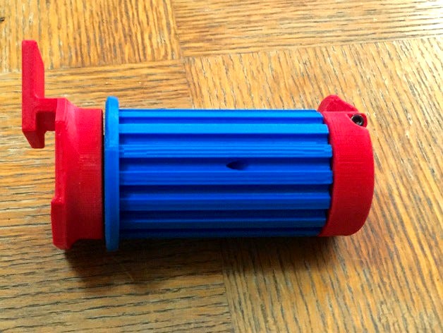
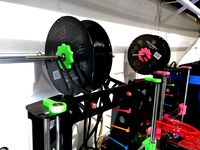
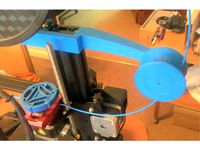
Here is my Almost-Frictionless Filament Spool Holder for the MakerBot Replicator 2x (and anything else which mounts spools the same way). It gives your printer a continuous, smooth feed of filament with no snags, friction hold-ups or other problems - which is great considering how weak the Replicator extruders' feed motors are. Having built one of these (and reprinted several parts because it failed in the middle) I tested it by using it to build another - and I didn't have to reprint anything that time around.
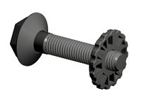
The design is based around an aluminium central shaft on which sit two skateboard bearings: that big rotor you can see sits on those bearings and touches no other part of the device: it moves smoothly and effortlessly. It's also only one millimeter less in diameter than the hole in the center of a spool of MakerBot filament, so those spools won't wander around on the holder any more: they'll be stable and predictable instead.
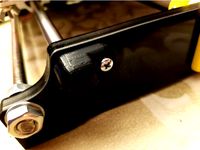
Spools click onto and off the holder over a spring-loaded catch which keeps them mounted firmly on the rotor until you decide you need to remove it. Meanwhile, the base of the device fits into the Replicator's existing filament holder holes: it's got a little design in it to grip that opening fairly securely, so it doesn't get pulled about.
Requirements
To build one of these, you'll need the following other supplies:
Two skateboard bearings, size 608 (the standard size for skateboard bearings); these are super-cheap: look on Amazon. I got these: http://www.amazon.com/gp/product/B002BBGTK6
One 20mm and two 30mm M3 socket cap screws (you can use a 20mm shoulder bolt instead of the 20mm screw if one is available); the screws are available at any hardware store; you may need to order shoulder bolts online. I didn't bother, and mine works fine.
A spring capable of raising the catch. The one I use measures 20mm in length by 9½ in diameter; it has a wire diameter of 1mm and contains seven coils, counting the ends, and it came in a package of assorted springs from Home Depot. It's probably overkill, but it's what I had lying around. As long as your spring has a 9 to 10-mm diameter and can raise the catch easily, you'll be fine. Here's the pack of springs I got; the one I used for this is the center one in the top row in the product image; there are four in the package: http://www.homedepot.com/p/Everbilt-Spring-Assortment-Kit-84-Pack-15642/202045461
An aluminium rod at least 109 mm long, with an 8 mm diameter, to fit the skateboard bearings. If you haven't done precise cuts and drills on round metal rods before, order enough to make four units (you need one rod per unit), because you're going to waste at least one or two of them learning to cut the metal properly: it's about getting used to the actual material being used. I already know how to cut metal, and (to my everlasting embarrassment) I still managed to screw up three before I finally got it right. I used this - it's aircraft grade, dead straight and almost impossible to bend by mistake: they come in one-foot lengths, so one bar can make two Rods: http://www.mcmaster.com/#9403t54
Recommended Tools
A drill with bits sized at 1/8" and something substantially smaller such as 1/16"; optionally a 7/64" bit as well (see below);
A metal saw (easiest if it's a metal saw blade in an electric saw);
A file, or sandpaper, or something you can use to abrade plastic;
A 2.5 mm Allen/Hex Key (the one which comes with the Replicator will do fine);
A light hammer such as a framing hammer (or a big hammer and a light touch!).
Printable Parts
Included in the printable objects for this device are the following:
A Base: the end which attaches to the Replicator;
A Rotor: the rotating part, which even has bearing oiling tubes in it, should you ever decide you need such a thing (just use a can of WD40 with its optional tube attached to the spray nozzle);
A Cap: the other end of the device;
A Catch: the spring-loaded element which retains the spool of filament;
A Bearing Alignment Tool: this helps you install a Bearing into the Rotor;
A Rod Template: this helps you cut the aluminium Rod to length and to drill holes in the right places.
Instructions
Notes
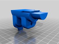
Study the rendered picture above showing all the components in their correct relative positions (minus the Rotor, which appears above everything else, for clarity). A picture speaks a thousand words...
When printing, always use a raft; you must also use supports for everything except the Rod Template, which doesn't require them. Using a raft ensures that all pieces are produced with a predictable size independent of the alignment of any specific printer's head. All parts except for the tools should be printed in high quality with layers sized at 0.15 mm or less, and with four shells. Refer to the relevant images above for further information. The component with least tolerance is the Catch; this should be printed with four shells and at least 20% infill, although I would recommend printing it on its own, with 50% or more infill, if you can be bothered to do so. My recommendation is to print the components with the alignments shown in the images above: these alignments are designed to produce components optimized to handle stress in the vectors they are expected to receive it, and print at slow speeds so that the resulting parts' measurements come out more exact. But, by all means, experiment.
It should go without saying that every part, once printed, needs to be made scrupulously clear of build-time support material and rafts, and so on: in this project, cleaning the parts is vitally important: (a) friction is your enemy, and with design tolerances down to a millimeter in many areas, extra bits of plastic will cause friction; (b) extra support material in some areas of the device, such as the Bearing sockets, will induce wobble caused by misalignment of dependent components, which leads to more friction. Don't be shy with sandpaper, files and so on!
To test for friction in the assembly, spin the Rotor - if all is correct, you shouldn't encounter any friction. If you do, try to find out where it's coming from and file that part down a little. Minor friction can sometimes be corrected by rotating the Rotor manually for a while, to allow it to wear down obstructions inside the device.
If you detect a large amount of friction, or if the device fails to rotate, check all parts for warping and reprint any which aren't perfectly straight. Realize that the only point of connection between the Rotor and either end part (Cap or Base) should be through the Bearings, via the Rod - in other words, when assembled, the Cap/Base and the Rotor should never come into contact with one another at all. If all the parts have printed properly and are clear of extraneous material, the design provides for at least a 1mm gap between the Rotor and any other printed part throughout the device (internally, near the bearing, that gap increases).
The Rod is responsible for maintaining alignment between the parts: if you detect periodic friction in the rotation, this could be because the Rod is slightly bent, or because the Bearings are not both perfectly aligned in their sockets, the misalignment causing the Rod to be off-centre. To determine if this is the case, remove both Cap and Base, hold the assembly horizontally by the Rotor and spin the Rod. If it isn't spinning perfectly straight (i.e. you see wobble in either of its ends), then you've found the problem. To determine whether the problem lies with the Rod or Bearings, remove the Rod and roll it on a known flat surface, such as a stone kitchen counter. If the Rod does not roll perfectly flat, it is causing the problem; if it does, then the problem is in the Bearings: check the sockets to ensure that they're uniform and free of debris.
Printing and Assembly
Print the Tools.
Print the Rotor. I recommend using four shells with only 15% of infill: the lighter the rotor, the less inertia it has, and the less trouble the printer's extruder motor will have turning it. Less than 15%, though, and it can begin to lose shape to some extent, especially on the parts which print horizontally. Once it has printed printed, it's especially important to clear out all support material from the center of the Rotor, most especially in the small housings where the Bearings will sit. The device is designed to print as few extraneous supports as possible in that area, but pay close attention to it nonetheless. Assuming you're printing the Rotor standing on its thick end (which you should be), it'll be that end's bearing housing which merits special attention.
While the Rotor is printing, you have plenty of time to prepare the aluminium Rod. Do this slowly and patiently: this part is crucial, and it's not as easy as it sounds to drill a perfectly-aligned hole through a round, smooth piece of metal, even with the Template's help, if you rush the process.
First, test the Rod as described in Note 6, above: if it's not perfectly straight, discard it and try another. Then insert the verified, straight Rod into the Template so that it butts up against the Template's closed end. Wrap blue tape around the center of the assembly so that the Rod doesn't move. Note that the Template tells you which end of the Rod is going to be which: remember this by marking - say - the "Base" end of the Rod with a marker or a piece of tape which will still be there when you've removed the Rod from the Template.
With the Rod fully inserted into the Template, use a metal-saw blade to cut off the protruding part of the Rod to make it the same length as its guide channel in the Template, following along the end of the template to help keep the blade straight.
Drill the holes. The Template is designed to allow you to drill right through it, and to help guide the drill bit, so try to be careful not to abrade the sides of the Template's guide holes, since this will cause it to become inaccurate. Use a very small (1/16" or 5/64") drill bit to do this; insert the bit all the way into the guide holes before you start drilling, then use the guide holes to help you drill a straight hole right through the Rod: do this pressing only lightly at first, since too much pressure on the Rod before there's a hole will make the drill bit slip. If possible, after drilling the first hole, leave a similarly-size drill bit or other object in the hole, sticking right through the Template and the Rod, to prevent the Rod from moving in the Template while you're drilling the second hole.
If you mess up a hole and decide it can't be used, simply turn the rod 90 degrees in the Template and try drilling both holes again: the Filament Holder won't care if there's an extra hole in the Rod, just as long as you can insert screws through the right place.
Once you've drilled both holes, remove the Rod from the Template and drill right through the holes you've already made, this time with a 1/8" drill bit, to widen them enough to accept M3 screws (use a 7/64" drill bit instead if you want the screws to cut a thread into the Rod: this makes the entire assembly fractionally tighter, but it makes disassembly and reassembly more difficult). If you wish, you can do this with the rod still mounted in the template: the process will be marginally easier, but it will ruin the tool's guide holes by making them too large for the Template to be used for another Rod, and there's no real need, since the larger drill bit should find its own way through the existing holes with no need for a guide.
Finally, file the Rod around the openings of the holes and around the edges of both ends to remove swarf, and to ensure everything is smooth. Test the Rod again to ensure that it's still dead straight: if not, you're back to step 3a again...
Print the rest of the objects (the Base, the Cap and the Catch).
While those objects are printing, insert the bearings into the Rotor. Use the Bearing Alignment tool to help: the Bearings fit extremely snugly. Put a bearing onto the corrugated end of the tool - if the fit is too tight, file the tool a little to make it easier. Align it with the socket in the rotor (the tool's fins should help you center it in the Rotor) and tap the end of the tool gently with a hammer while the Bearing seats itself. You can also tap around the edge of the bearing with a hammer and a rod. Only tap the edges, though: the Bearing is delicate and you'll damage it if you hit it anywhere else.
Assemble the Cap to the Rod. Use the marking you made earlier to know which end of the Rod to put into the Cap. Be very careful not to damage the opening of the tube into which the Rod fits: this is the Cap's contact point with its Bearing. You can line up the bolt holes by looking through the upward-facing part of the Cap, where the Spring and Catch will sit. The Rod fits into the Cap extremely tightly, so insert a screw into the hole at the other end of the Rod to give yourself leverage, so that you can turn the Rod easily. Once you've got the Cap and the Rod lined up correctly, screw them together from the underside of the cap using a 30mm M3 socket cap screw.
Test that the Catch can move freely in the opening provided for it in the Cap, and that it can rotate properly on a 20mm M3 socket cap screw. If it can't move properly in the Cap, file or sand it and/or the Cap until it can; if it can't rotate properly on the Screw, drill through the hole in the Catch with a 1/8" drill bit.
Insert the Spring into the socket provided for it in the Catch, then mate that to the Cap and holding it together with one hand so that the bolt holes in both line up, and insert the 20mm M3 socket cap screw or elbow bolt into the assembly with the other hand.
After tightening the screw into place, ensure that the catch moves properly and freely: if it sticks, then either the screw is too tight and is compressing the mounting into the catch, grabbing it, or else there's some support material from the print process still attached to one of the objects. This completes the Cap assembly.
Insert the Rod into the Rotor's thin end, threading it through the Bearings you installed earlier, pushing the Rotor all the way up to the Cap. This may take patience: there's virtually zero tolerance between the Rod and the Bearings. If it proves impossible to insert the Rod into a Bearing, use a small amount of oil on the end of the rod to make the process easier; if this fails, file the end of the Rod very slightly so that it fits. Once you've completed this, you should have a Cap and Rotor sitting properly together, with the thin end of the Rotor pointing at the Cap and the thick end pointing away; there should be roughly a millimeter gap between the visible parts of the Cap and Rotor. Test for and correct any friction, as described in the Notes, above. If the Cap and Rotor touch, it means that something has printed incorrectly; rather than reprinting it, however, you may be able to get away with wearing away a bit of the Rotor's Cap-facing end using an orbital sander with a medium-grit paper (remember to remove any melted plastic residue afterwards).
Having ensured that the Rotor spins freely on the Cap, assemble the Base to the Rod. You can line this up easily by following a spine on the rotor between the screw holes on the Base and Cap, lining them up by eye. Before securing the Base, ensure that the Rotor still spins freely, and make corrections if necessary, as with the Cap. Then secure the Base to the Rod using another 30mm M3 socket cap screw. This completes the device assembly.
Test the movement of the device. There should be no detectable friction. Remember to test it by moving it slowly as well as by spinning it quickly: small obstructions will be undetectable at speed but very obvious at fractional RPM, which is how the device will operate in the real world.
Enjoy.
The design is based around an aluminium central shaft on which sit two skateboard bearings: that big rotor you can see sits on those bearings and touches no other part of the device: it moves smoothly and effortlessly. It's also only one millimeter less in diameter than the hole in the center of a spool of MakerBot filament, so those spools won't wander around on the holder any more: they'll be stable and predictable instead.
Spools click onto and off the holder over a spring-loaded catch which keeps them mounted firmly on the rotor until you decide you need to remove it. Meanwhile, the base of the device fits into the Replicator's existing filament holder holes: it's got a little design in it to grip that opening fairly securely, so it doesn't get pulled about.
Requirements
To build one of these, you'll need the following other supplies:
Two skateboard bearings, size 608 (the standard size for skateboard bearings); these are super-cheap: look on Amazon. I got these: http://www.amazon.com/gp/product/B002BBGTK6
One 20mm and two 30mm M3 socket cap screws (you can use a 20mm shoulder bolt instead of the 20mm screw if one is available); the screws are available at any hardware store; you may need to order shoulder bolts online. I didn't bother, and mine works fine.
A spring capable of raising the catch. The one I use measures 20mm in length by 9½ in diameter; it has a wire diameter of 1mm and contains seven coils, counting the ends, and it came in a package of assorted springs from Home Depot. It's probably overkill, but it's what I had lying around. As long as your spring has a 9 to 10-mm diameter and can raise the catch easily, you'll be fine. Here's the pack of springs I got; the one I used for this is the center one in the top row in the product image; there are four in the package: http://www.homedepot.com/p/Everbilt-Spring-Assortment-Kit-84-Pack-15642/202045461
An aluminium rod at least 109 mm long, with an 8 mm diameter, to fit the skateboard bearings. If you haven't done precise cuts and drills on round metal rods before, order enough to make four units (you need one rod per unit), because you're going to waste at least one or two of them learning to cut the metal properly: it's about getting used to the actual material being used. I already know how to cut metal, and (to my everlasting embarrassment) I still managed to screw up three before I finally got it right. I used this - it's aircraft grade, dead straight and almost impossible to bend by mistake: they come in one-foot lengths, so one bar can make two Rods: http://www.mcmaster.com/#9403t54
Recommended Tools
A drill with bits sized at 1/8" and something substantially smaller such as 1/16"; optionally a 7/64" bit as well (see below);
A metal saw (easiest if it's a metal saw blade in an electric saw);
A file, or sandpaper, or something you can use to abrade plastic;
A 2.5 mm Allen/Hex Key (the one which comes with the Replicator will do fine);
A light hammer such as a framing hammer (or a big hammer and a light touch!).
Printable Parts
Included in the printable objects for this device are the following:
A Base: the end which attaches to the Replicator;
A Rotor: the rotating part, which even has bearing oiling tubes in it, should you ever decide you need such a thing (just use a can of WD40 with its optional tube attached to the spray nozzle);
A Cap: the other end of the device;
A Catch: the spring-loaded element which retains the spool of filament;
A Bearing Alignment Tool: this helps you install a Bearing into the Rotor;
A Rod Template: this helps you cut the aluminium Rod to length and to drill holes in the right places.
Instructions
Notes
Study the rendered picture above showing all the components in their correct relative positions (minus the Rotor, which appears above everything else, for clarity). A picture speaks a thousand words...
When printing, always use a raft; you must also use supports for everything except the Rod Template, which doesn't require them. Using a raft ensures that all pieces are produced with a predictable size independent of the alignment of any specific printer's head. All parts except for the tools should be printed in high quality with layers sized at 0.15 mm or less, and with four shells. Refer to the relevant images above for further information. The component with least tolerance is the Catch; this should be printed with four shells and at least 20% infill, although I would recommend printing it on its own, with 50% or more infill, if you can be bothered to do so. My recommendation is to print the components with the alignments shown in the images above: these alignments are designed to produce components optimized to handle stress in the vectors they are expected to receive it, and print at slow speeds so that the resulting parts' measurements come out more exact. But, by all means, experiment.
It should go without saying that every part, once printed, needs to be made scrupulously clear of build-time support material and rafts, and so on: in this project, cleaning the parts is vitally important: (a) friction is your enemy, and with design tolerances down to a millimeter in many areas, extra bits of plastic will cause friction; (b) extra support material in some areas of the device, such as the Bearing sockets, will induce wobble caused by misalignment of dependent components, which leads to more friction. Don't be shy with sandpaper, files and so on!
To test for friction in the assembly, spin the Rotor - if all is correct, you shouldn't encounter any friction. If you do, try to find out where it's coming from and file that part down a little. Minor friction can sometimes be corrected by rotating the Rotor manually for a while, to allow it to wear down obstructions inside the device.
If you detect a large amount of friction, or if the device fails to rotate, check all parts for warping and reprint any which aren't perfectly straight. Realize that the only point of connection between the Rotor and either end part (Cap or Base) should be through the Bearings, via the Rod - in other words, when assembled, the Cap/Base and the Rotor should never come into contact with one another at all. If all the parts have printed properly and are clear of extraneous material, the design provides for at least a 1mm gap between the Rotor and any other printed part throughout the device (internally, near the bearing, that gap increases).
The Rod is responsible for maintaining alignment between the parts: if you detect periodic friction in the rotation, this could be because the Rod is slightly bent, or because the Bearings are not both perfectly aligned in their sockets, the misalignment causing the Rod to be off-centre. To determine if this is the case, remove both Cap and Base, hold the assembly horizontally by the Rotor and spin the Rod. If it isn't spinning perfectly straight (i.e. you see wobble in either of its ends), then you've found the problem. To determine whether the problem lies with the Rod or Bearings, remove the Rod and roll it on a known flat surface, such as a stone kitchen counter. If the Rod does not roll perfectly flat, it is causing the problem; if it does, then the problem is in the Bearings: check the sockets to ensure that they're uniform and free of debris.
Printing and Assembly
Print the Tools.
Print the Rotor. I recommend using four shells with only 15% of infill: the lighter the rotor, the less inertia it has, and the less trouble the printer's extruder motor will have turning it. Less than 15%, though, and it can begin to lose shape to some extent, especially on the parts which print horizontally. Once it has printed printed, it's especially important to clear out all support material from the center of the Rotor, most especially in the small housings where the Bearings will sit. The device is designed to print as few extraneous supports as possible in that area, but pay close attention to it nonetheless. Assuming you're printing the Rotor standing on its thick end (which you should be), it'll be that end's bearing housing which merits special attention.
While the Rotor is printing, you have plenty of time to prepare the aluminium Rod. Do this slowly and patiently: this part is crucial, and it's not as easy as it sounds to drill a perfectly-aligned hole through a round, smooth piece of metal, even with the Template's help, if you rush the process.
First, test the Rod as described in Note 6, above: if it's not perfectly straight, discard it and try another. Then insert the verified, straight Rod into the Template so that it butts up against the Template's closed end. Wrap blue tape around the center of the assembly so that the Rod doesn't move. Note that the Template tells you which end of the Rod is going to be which: remember this by marking - say - the "Base" end of the Rod with a marker or a piece of tape which will still be there when you've removed the Rod from the Template.
With the Rod fully inserted into the Template, use a metal-saw blade to cut off the protruding part of the Rod to make it the same length as its guide channel in the Template, following along the end of the template to help keep the blade straight.
Drill the holes. The Template is designed to allow you to drill right through it, and to help guide the drill bit, so try to be careful not to abrade the sides of the Template's guide holes, since this will cause it to become inaccurate. Use a very small (1/16" or 5/64") drill bit to do this; insert the bit all the way into the guide holes before you start drilling, then use the guide holes to help you drill a straight hole right through the Rod: do this pressing only lightly at first, since too much pressure on the Rod before there's a hole will make the drill bit slip. If possible, after drilling the first hole, leave a similarly-size drill bit or other object in the hole, sticking right through the Template and the Rod, to prevent the Rod from moving in the Template while you're drilling the second hole.
If you mess up a hole and decide it can't be used, simply turn the rod 90 degrees in the Template and try drilling both holes again: the Filament Holder won't care if there's an extra hole in the Rod, just as long as you can insert screws through the right place.
Once you've drilled both holes, remove the Rod from the Template and drill right through the holes you've already made, this time with a 1/8" drill bit, to widen them enough to accept M3 screws (use a 7/64" drill bit instead if you want the screws to cut a thread into the Rod: this makes the entire assembly fractionally tighter, but it makes disassembly and reassembly more difficult). If you wish, you can do this with the rod still mounted in the template: the process will be marginally easier, but it will ruin the tool's guide holes by making them too large for the Template to be used for another Rod, and there's no real need, since the larger drill bit should find its own way through the existing holes with no need for a guide.
Finally, file the Rod around the openings of the holes and around the edges of both ends to remove swarf, and to ensure everything is smooth. Test the Rod again to ensure that it's still dead straight: if not, you're back to step 3a again...
Print the rest of the objects (the Base, the Cap and the Catch).
While those objects are printing, insert the bearings into the Rotor. Use the Bearing Alignment tool to help: the Bearings fit extremely snugly. Put a bearing onto the corrugated end of the tool - if the fit is too tight, file the tool a little to make it easier. Align it with the socket in the rotor (the tool's fins should help you center it in the Rotor) and tap the end of the tool gently with a hammer while the Bearing seats itself. You can also tap around the edge of the bearing with a hammer and a rod. Only tap the edges, though: the Bearing is delicate and you'll damage it if you hit it anywhere else.
Assemble the Cap to the Rod. Use the marking you made earlier to know which end of the Rod to put into the Cap. Be very careful not to damage the opening of the tube into which the Rod fits: this is the Cap's contact point with its Bearing. You can line up the bolt holes by looking through the upward-facing part of the Cap, where the Spring and Catch will sit. The Rod fits into the Cap extremely tightly, so insert a screw into the hole at the other end of the Rod to give yourself leverage, so that you can turn the Rod easily. Once you've got the Cap and the Rod lined up correctly, screw them together from the underside of the cap using a 30mm M3 socket cap screw.
Test that the Catch can move freely in the opening provided for it in the Cap, and that it can rotate properly on a 20mm M3 socket cap screw. If it can't move properly in the Cap, file or sand it and/or the Cap until it can; if it can't rotate properly on the Screw, drill through the hole in the Catch with a 1/8" drill bit.
Insert the Spring into the socket provided for it in the Catch, then mate that to the Cap and holding it together with one hand so that the bolt holes in both line up, and insert the 20mm M3 socket cap screw or elbow bolt into the assembly with the other hand.
After tightening the screw into place, ensure that the catch moves properly and freely: if it sticks, then either the screw is too tight and is compressing the mounting into the catch, grabbing it, or else there's some support material from the print process still attached to one of the objects. This completes the Cap assembly.
Insert the Rod into the Rotor's thin end, threading it through the Bearings you installed earlier, pushing the Rotor all the way up to the Cap. This may take patience: there's virtually zero tolerance between the Rod and the Bearings. If it proves impossible to insert the Rod into a Bearing, use a small amount of oil on the end of the rod to make the process easier; if this fails, file the end of the Rod very slightly so that it fits. Once you've completed this, you should have a Cap and Rotor sitting properly together, with the thin end of the Rotor pointing at the Cap and the thick end pointing away; there should be roughly a millimeter gap between the visible parts of the Cap and Rotor. Test for and correct any friction, as described in the Notes, above. If the Cap and Rotor touch, it means that something has printed incorrectly; rather than reprinting it, however, you may be able to get away with wearing away a bit of the Rotor's Cap-facing end using an orbital sander with a medium-grit paper (remember to remove any melted plastic residue afterwards).
Having ensured that the Rotor spins freely on the Cap, assemble the Base to the Rod. You can line this up easily by following a spine on the rotor between the screw holes on the Base and Cap, lining them up by eye. Before securing the Base, ensure that the Rotor still spins freely, and make corrections if necessary, as with the Cap. Then secure the Base to the Rod using another 30mm M3 socket cap screw. This completes the device assembly.
Test the movement of the device. There should be no detectable friction. Remember to test it by moving it slowly as well as by spinning it quickly: small obstructions will be undetectable at speed but very obvious at fractional RPM, which is how the device will operate in the real world.
Enjoy.
Similar models
thingiverse
free

Alignment Locking Pins by Pop4solar
...hole for a tight locking fit. of course you will need to print two sets, one for each side of the box. i hope this helps someone.
thingiverse
free

Printrbot Drill Template for Al Y Bearing Blocks by wd5gnr
...ve predrilled holes for the printrbot aluminum y bearing blocks, you can print this template to help you drill holes in the deck.
thingiverse
free
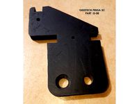
GEEETECH PRUSA i3 PART i3-08 by akrnzz
...hould be drilled for smooth and accurate surfaces, the threaded rod should get a 6mm end on a lathe to fit into the ball bearing.
thingiverse
free

Tricklaser Hospital
...stuff which isn't nearly as strong). loctite makes a similar plastic epoxy. you may wish to place a small...
thingiverse
free

Dock Fishing Rod Handle by LiamKelly125
...od or reel doesn't really matter it just matters if your rod is the male end of the rod. almost any two part rod should work.
thingiverse
free

Left Barbie Prosthetic Leg by ajsenczy
...needs to be drilled, drill hole
-attach using a small nail, snip and secured sides with superglue
have fun with your new barbie!
thingiverse
free

Spool holder (for common 0,75kg spools) by pomaer
...spool_holder_base printed twice spool_holder_arm printed once 8 m5x20 or similar length, no less then 15, no more then 30!...
thingiverse
free
Spengler Wand - Screw caps by Jimsy33
...ed the version with the hole in tpu to make the task even easier, you can simply use a rod or drill bit to bend/pull the cap out.
thingiverse
free
Tap & Drill Alignment Tool for 20x20mm Extrusion by Michaelo
...better precision. that's pretty much all you can do with plastic, it's time for a 3d printer that prints aluminum...
mike
thingiverse
free
Anet A8 Basic Y Axis Upgrade by danohpsp
...it. i found that the pla printed endcap flexes less than the acrylic endcaps which adds regidity to the table support structure.

Frictionless
thingiverse
free
Frictionless spool holder for ender 3
...frictionless spool holder for ender 3
thingiverse
used of old wheel roller
thingiverse
free
Hatchbox Frictionless Spoolholder by Miaviator
... frictionless spoolholder by miaviator
thingiverse
the spool holder listed doesn't fit hatchbox filaments. so i fixed it.
thingiverse
free

Frictionless Gear Extra Credit by R1ckG2
...aterials. these were inspired by frictionless gears, and how the cylinders should be able to rotate and still stay in the slots.
thingiverse
free
frictionless filament guide with bearing wheel by dretful
...ount instead of the holder this comes from. this arm and all the others like it fit ok. i found this mount was not very strong.
thingiverse
free
Frictionless Spool mount Creality Ender 3 by ahdesign
...s, one of each, except for part 02, here you need two. and you will get a spool holder wich fit many of the spools on the market.
thingiverse
free

Frictionless UFO with Stand by PrintTo3D
...ing levitate or modify it.
updates 11-8-10
video added!http://www.youtube.com/watch?v=1czugrwv300
uploaded stand with mouthpiece.
thingiverse
free

Frictionless Spool Holder for 2020 Aluminium Extrusion by AxMod3DPrint
...2020 aluminium extrusion. this is used on the fb2020 core xy 3d printers.
bom:
150mm m8 threaded rod
4x 608zz bearings
3x m8 nut
thingiverse
free

Hovering Disk - DIY 3D Printed - Frictionless Motion Experiment by fgebhart
...e the disk in action:https://youtu.be/wl0n9uzzohq
to demonstrate the hovering effect use even surfaces like glass or flat tables.
thingiverse
free

"Frictionless" PLA spool holder by Dimon372
...d spools are 38.2 mm diameter.
funny, but i had to print different sizes models for one spool. it's different on both sides.
thingiverse
free

Frictionless spool holder for Malyan M320 by monsieurglad
...85mm).
you need: two (2) bearings 608 (608zz, for skateboard, etc)
reuse the original metal part.
slide in place, easy to remove.
Replicator
turbosquid
$5

Bucati USB Stick "replic"
... available on turbo squid, the world's leading provider of digital 3d models for visualization, films, television, and games.
3d_export
$75

3D Scania S730 8x4 Recovery SWS Edition
... of work with custom made parts to replicate the real truck unit<br>textures included<br>format available : obj files
3ddd
$1

Restoration Hardware - 1950s Dutch Shipyard Triple Shelving
...right to access the lofty upper shelves. crafted from solid walnut and iron, its antiqued finish replicates an aged, worn patina.
3d_export
$50

3D Scania Vabis 110 Model
...s 110 truck<br>very detailed and accurate replicated model<br>textures included<br>format available : obj files
3d_export
$11

Batman
...eled to replicate the original lego model to meet the highest quality , each part are arranged in hierarchy and parented objects.
3d_export
$85

3D Scania S730T Omars Recovery Truck Model
...ded<br>format available: obj file<br>on request,after purchase,i can offer other file formats the customer is in need
3d_ocean
$10
Star Wars: Anakin Skywalker Lightsaber
...tsaber of anakin skywalker. it contains a fairly high amount of polygons, suitable for semi-close up renders. main focus is it...
3d_ocean
$30

Ashley Jaidyn Poster Bedroom Set
...esser, mirror, chest. all models are made in compliance with the proportions and sizes of real furniture. with the replicated ...
3d_ocean
$10
Ashley Stages Chest
...w x 16”d x 49”h. material: wood products and other. color: replicated pine grain. this model is made in accordance with the pr...
3d_ocean
$6
Ashley Stages Table Lamp
...other. color: replicated pine grain. this model is made in accordance with the proportions and sizes of real furniture. the di...
2X
3ddd
$1
modular u shape 2x
...modular u shape 2x
3ddd
modular
точечный светильник modular u shape 2x
turbosquid
$20

Modern Sofa 2x
... available on turbo squid, the world's leading provider of digital 3d models for visualization, films, television, and games.
turbosquid
$7

Spartan Helmets 2x
... available on turbo squid, the world's leading provider of digital 3d models for visualization, films, television, and games.
turbosquid
$4

Grenade Pack 2x
... available on turbo squid, the world's leading provider of digital 3d models for visualization, films, television, and games.
3d_ocean
$17

Modern Sofa 2x
...only tri and quad polygons) • real-world sizes and proportions • the model is grouped for easy selection and placing in your s...
archive3d
free
Sofa 2x 3D Model
...sofa 2x 3d model
archive3d
sofa divan
archive3d
free

Bed 2x 3D Model
...bed 2x 3d model
archive3d
bed beds
archive3d
free

Sofa 2x 3D Model
...sofa 2x 3d model
archive3d
sofa silik
archive3d
free

Case 2x 3D Model
...case 2x 3d model
archive3d
wardrobe case
3ddd
$1

Butterfly Sofa 2x
...butterfly sofa 2x
3ddd
butterfly
полезный диванчик для гостиной. в двух цветовых решениях
Almost
turbosquid
$150

almost done.c4d
... available on turbo squid, the world's leading provider of digital 3d models for visualization, films, television, and games.
turbosquid
$2

Booker almost final.max
... available on turbo squid, the world's leading provider of digital 3d models for visualization, films, television, and games.
3ddd
$1

Обои ECO, коллекция Almost white
...бесшовные. размер текстур: от 1083х1083 до 2048х1024 пикселей. ссылка на коллекцию –http://www.eco.se/ru/collection-42/
3d_export
$5

Coachtablearmchair 3D Model
...coachtablearmchair 3d model 3dexport almost free coachtablearmchair 3d model freeon 24073...
digiprops
$6
Yellow concrete parking stopper #01
...#01 digiprops yellow concrete parking stopper with two bolts. almost new, very little...
3ddd
$1
Saki Pendant-light
...a tribute to this unforgotten island, recognized by its almost extinct bamboo roots...
3d_export
$5

acoustic guitar
...cycles, when using the eevee render, the quality remains almost unchanged.the model is perfect for large renders, since the...
3d_export
$8

House
...or school work a modern style house of 12x26m almost completely finished includes plan in >(.layout) and (png)m formats...
3d_ocean
$5

Glas of Red Wine with Bottle
...wine glas a glas of red wine and an almost empty...
3d_export
$5

radiator
...detailed radiator modelled in blender. this can be used almost anywhere, however it is not a low poly model,...
Spool
3ddd
$1

spool c53301
...spool c53301
3ddd
spool
spool c53301 650х350х145
turbosquid
$3

Cable Spool
...royalty free 3d model cable spool for download as max and fbx on turbosquid: 3d models for games, architecture, videos. (1457009)
turbosquid
free

Pallets and Spool
... available on turbo squid, the world's leading provider of digital 3d models for visualization, films, television, and games.
turbosquid
$10

Spool of String
...ol of string pink for download as c4d, 3ds, fbx, obj, and stl on turbosquid: 3d models for games, architecture, videos. (1647892)
3ddd
$1

Подвесные светильники Spool
...ye/podvesnoy_svetilnik_spool_d320/ http://www.cosmorelax.ru/catalog/podvesnyye/podvesnoy_svetilnik_spool_d420/
3ddd
free

Spool 001 sofa
...spool 001 sofa
3ddd
roda
roda
collection spool
design rodolfo dordoni
dimensions:
lenght 90 cm
depth 94 cm
height 79 cm
turbosquid
$15

Roda Spool Sofa
...ee 3d model roda spool sofa for download as max, obj, and fbx on turbosquid: 3d models for games, architecture, videos. (1502650)
turbosquid
$95
wire spools 3ds
... available on turbo squid, the world's leading provider of digital 3d models for visualization, films, television, and games.
turbosquid
$20
spool of TV wire
... available on turbo squid, the world's leading provider of digital 3d models for visualization, films, television, and games.
turbosquid
$3

Simple and Fast Spool Holder
...ree 3d model simple and fast spool holder for download as stl on turbosquid: 3d models for games, architecture, videos. (1548546)
Filament
3ddd
$1
Filament Cage
...filament cage
3ddd
лофт , filament cage
модель бра, делалась по фото!
turbosquid
$3
FILAMENT COUNTER
...d
royalty free 3d model filament counter for download as stl on turbosquid: 3d models for games, architecture, videos. (1563049)
3d_export
$5

Filament lamp 3D Model
...filament lamp 3d model
3dexport
filament lamp 3d model kevin 54161 3dexport
3d_export
$5

Filament bulb candle 3D Model
...filament bulb candle 3d model
3dexport
filament bulb-candle
filament bulb candle 3d model kevin 54163 3dexport
3d_export
$5

Filament led light bulb
...filament led light bulb
3dexport
realistic 3d model of filament light bulb with v-ray materials.
3d_export
$5

Filament led light bulb
...filament led light bulb
3dexport
realistic 3d model of filament light bulb with v-ray materials.
3d_export
$5

Filament led light bulb
...filament led light bulb
3dexport
realistic 3d model of filament light bulb with v-ray materials.
3d_export
$5
Filament led light bulb
...filament led light bulb
3dexport
realistic 3d model of filament light bulb with v-ray materials.
3d_export
$5

Filament led light bulb
...filament led light bulb
3dexport
realistic 3d model of filament light bulb with v-ray materials.
3ddd
$1
Factory filament metal shade
...factory filament metal shade
3ddd
restoration hardware
restoration hardware. 20th c. factory filament metal shade.
Holder
archibase_planet
free
Holder
...holder
archibase planet
holder toilet paper holder
holder paper n070712 - 3d model (*.gsm+*.3ds) for interior 3d visualization.
archibase_planet
free
Holder
...e planet
holder rack toilet paper holder
holder toilet roll n240715 - 3d model (*.gsm+*.3ds+*.max) for interior 3d visualization.
archibase_planet
free
Holder
...holder
archibase planet
pen holder support prop
pen holder - 3d model for interior 3d visualization.
archibase_planet
free
Holder
...holder
archibase planet
pole post holder
сhurch cross pole holder - 3d model for interior 3d visualization.
archibase_planet
free
Holder
...holder
archibase planet
holder bathroom ware
shower holder - 3d model (*.gsm+*.3ds) for interior 3d visualization.
archibase_planet
free
Holder
...oilet paper holder
holder paper devon&devon; time black n241113 - 3d model (*.gsm+*.3ds+*.max) for interior 3d visualization.
archibase_planet
free
Holder
...holder
archibase planet
holder hanger hanger for towel
holder 7 - 3d model (*.gsm+*.3ds) for interior 3d visualization.
archibase_planet
free
Holder
...holder
archibase planet
holder hanger hanger for towel
holder 3 - 3d model (*.gsm+*.3ds) for interior 3d visualization.
archibase_planet
free
Holder
...holder
archibase planet
holder towel rack towel-horse
holder - 3d model (*.gsm+*.3ds) for interior 3d visualization.
archibase_planet
free
Holder
...lder
archibase planet
holder hanger hanger for towel
holder towel n250912 - 3d model (*.gsm+*.3ds) for interior 3d visualization.