Thingiverse
Air Quality & Aerosol (VOC) Sensor and Alarm by Spo_ck
by Thingiverse
Last crawled date: 3 years, 4 months ago
Air Quality & Aerosol (VOC) Sensor and Alarm
Please also have a look on my GitHub:https://github.com/Spo-ck/Air-Quality-Aerosol-VOC-Sensor-and-Alarm
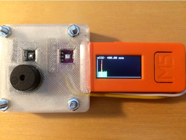
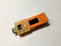
During the COVID-19 Pandemic, monitoring the Air Quality is important. Because of this, I developed this compact Air Quality Monitor based on the M5StickC Microcontroller and the SGP30 Sensor. The System is very small and can also be worn as a smart watch. When the eCO2 hits the threshold of 1000 ppm or the TVOC hit the threshold of 150 ppb, the sensor will trigger an alarm (sound and lght), so that you can leave a dangerous and potentially infectious room or open the windows.
System as Smart Watch close up
System as Smart Watch
Electronic
Part List
Electronic
Buzzer module
BME280 Barometric Sensor
GY-SGP30 Gas Sensor (alternative Grove SGP30)
M5StickC Microcontroller
Grove Sensor Cable
PCB
Generic 1x8 Pin Header 2,54mm
Generic solid core wires (PCB)
Generic Lead Solder
Tools
Soldering Station
Solder Pump
Third Hand
Soldering Tools
Pin Mapping
GND: Buzzer Module -, BME280 GND, SGP30 GND
3.3V: Buzzer Module +, BME280 VIN, SGP30 VIN
G26: Buzzer Module S
G32: BME280 SDA, SGP30 SDA
G33: BME280 SCL, SGP30 SCL
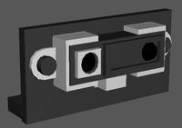
Electronic Schematic
Assembly
The system basically consists out of the M5StickC Microcontroller, a Buzzer Module, a BME280 Barometric Sensor Module (Temperature, Humidity, Pressure) and an SGP30 Gas Sensor Module (eCO2, TVOC, Ethanol, H2). The Buzzer Module is connected to the M5StickCs Pin Header, and the seonsors are connected to the I2C bus via the Grove connector.
All 3 components are soldered together on a single prototyping PCB. To this prototyping PCB is then soldered a 1x8 Pin Header (2.54mm) so that the PCB can be connected to the front pin header of the M5StickC. As power supply off all 3 modules, the 3.3V and the GND Pin of the M5StickCs Pin Header are utilized. The Buzzer-Modules signal pin is soldered to Pin 26, because this pin allows output signals.
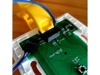
Because of the sensor modules need to be connected to the I2C Bus, which is only available on the Grove connector of the M5StickC, a 20cm Grove sensor cable was utilized. One connector was cutted of, and the 5V and GND Cables were removed. The remaining Yeallow (G32, SDA) and white (G33, SCL) cables were soldered to the corresponding pins on the PCD, to connect them to the sensor module
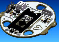
PCB Front
PCB Back
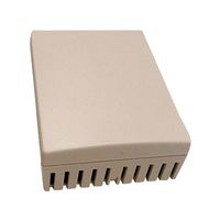
PCB Cased
3D-Printing
Settings
Profile: 0.2mm
Infill: 10%
Support: Yes
Parts
Filament: PLA (OWL-Filament)
Printer: Creality Ender 3
Generic M3 Screws
Assembly
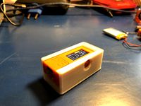
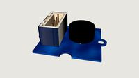
The Sensor PCB Case consists out of 3 parts, a body frame, a front and a bottom part. For the Assembly, the Soldered PCB is first fittet into the Body Frame from the bottom so that the case mathes the pin header exactly. The Sensor cable is the placed into the small hole on the top side of the frame. After that, the Front and Bottom Party are crewed to the case. The Screwd sensor case it then first plugged into the Pin Header of the M5StickC. After that, the Sensor Cable is plugged into the Grove Connecter.
PCB Cased
System Detailed View
Arduino Code
You can download the code from my Github
Libraries
M5StickC
Wire.h
Adafruit_Sensor.h
Adafruit_SGP30.h
Adafruit_BME280.h
EEPROM.h
About the Code
The purpose of this Microcontroller Code is to generate sensor data from the sensors connected to trigger an Alarm when the Air Quality is bad. For this reason, the SGP30 Sensor Module measures eCO2 and TVOC in the breathing Air. The BME280 Barometric Sensor is required to calibrate the SGP30, and therefore to enhance its accuracy.
When the eCO2 value is over 1000 ppm, or the TVOC value is over 150 ppb, an alarm is triggered. The alarm will result in an alarm sound provided by the buzzer modele, the built in LED enlight in RED and the display turning RED. By the built in settings options, the Buzzer can also set into silent mode, where only the LED and the Display are tiggered in case of an alarm. The alarm sound is only triggered once in 60s, when the eCO2 or TVOC value hits the threshold value, but the LED will be enlighted in RED untill the Sensor Value is below the threshold again. In addition, the buzzer then disabled for 1 minute. Because of this, you will not hear multible buzzer alarms, when the sensor value is falling below, and hitting the threshold again within one minute.
System Alarm
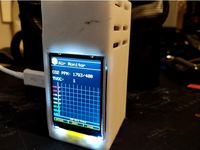
The System has three built in views. The Detailed View shows only the eCO2 and the TVOC values, whereas the Air Quality view shows the Time, Temperature, Humidity and the Battery Status in addition. More advanced is the Chart View, which shows the eCO2 value for the last 20min. If the critical threshold was hit, the bar shown will turn red, and if the value is below, the bar will be green.
To navigate through the different views, the front button (Button A) is used. The last view is also stored in EEPROM, so that the sensor will start in the last used view when it starts next time.
System Detailed View
System Air Quality View
System Chart View
Nomally, the display is On all time, but it is also possible to disable the display. In this mode, the front button needs to be pressed one time to turn the display on for 5s. After that, pressing this button again will make the view change as usual.
In addidion, a settings view is implemented. In the settings view, one can change the Display Mode (Display always on or on for 5s) and the Alarm Mode (Buzzer turned off or on). This view is opened when the side button (Button B) is pressed. In this view, the first option it the Display Mode. When the Front Button is pressed, the Mode will change (Display always on or on for 5s). The option is confirmed with pressind the side button again. After that, the settings for the Alarm Mode (Buzzer turned off or on) is opened and can be changed with pressing the front button. In general, the active settings option is indicated with a red line on the left side. Pressing the side button a third time will confirm the settings, and open the last Sensor View again.
System Settings
How To
In order to flash this code on the M5StickC, the Arduino IDE needs to download and to be installed first. Then, the M5StickCs driver and the above mentioned libraries need to be installed. You can then open (or copy/past) the code into the IDE and flash it.
M5StickC Manual and Software
Arduino IDE
Still tp be implemented
Every Gas Sensor is different, so it also needs to be calibrated. In order to calibrate it, it needs to be turned on for 12h, and this value is then valid for 7 days. To do so, the value needs to be stored in EEPROM, and send to the sensor in the Settings function. Because I never used it for 12h, this is not implemented yet. If not set, the sensor used 400 ppm for eCO2 and 0 ppb for TVOC as calibration value.
Also, it was not possible to set the display off completely. In the current implementation, it will only be black in the 5s-On mode and not completely off.
Please also have a look on my GitHub:https://github.com/Spo-ck/Air-Quality-Aerosol-VOC-Sensor-and-Alarm
During the COVID-19 Pandemic, monitoring the Air Quality is important. Because of this, I developed this compact Air Quality Monitor based on the M5StickC Microcontroller and the SGP30 Sensor. The System is very small and can also be worn as a smart watch. When the eCO2 hits the threshold of 1000 ppm or the TVOC hit the threshold of 150 ppb, the sensor will trigger an alarm (sound and lght), so that you can leave a dangerous and potentially infectious room or open the windows.
System as Smart Watch close up
System as Smart Watch
Electronic
Part List
Electronic
Buzzer module
BME280 Barometric Sensor
GY-SGP30 Gas Sensor (alternative Grove SGP30)
M5StickC Microcontroller
Grove Sensor Cable
PCB
Generic 1x8 Pin Header 2,54mm
Generic solid core wires (PCB)
Generic Lead Solder
Tools
Soldering Station
Solder Pump
Third Hand
Soldering Tools
Pin Mapping
GND: Buzzer Module -, BME280 GND, SGP30 GND
3.3V: Buzzer Module +, BME280 VIN, SGP30 VIN
G26: Buzzer Module S
G32: BME280 SDA, SGP30 SDA
G33: BME280 SCL, SGP30 SCL
Electronic Schematic
Assembly
The system basically consists out of the M5StickC Microcontroller, a Buzzer Module, a BME280 Barometric Sensor Module (Temperature, Humidity, Pressure) and an SGP30 Gas Sensor Module (eCO2, TVOC, Ethanol, H2). The Buzzer Module is connected to the M5StickCs Pin Header, and the seonsors are connected to the I2C bus via the Grove connector.
All 3 components are soldered together on a single prototyping PCB. To this prototyping PCB is then soldered a 1x8 Pin Header (2.54mm) so that the PCB can be connected to the front pin header of the M5StickC. As power supply off all 3 modules, the 3.3V and the GND Pin of the M5StickCs Pin Header are utilized. The Buzzer-Modules signal pin is soldered to Pin 26, because this pin allows output signals.
Because of the sensor modules need to be connected to the I2C Bus, which is only available on the Grove connector of the M5StickC, a 20cm Grove sensor cable was utilized. One connector was cutted of, and the 5V and GND Cables were removed. The remaining Yeallow (G32, SDA) and white (G33, SCL) cables were soldered to the corresponding pins on the PCD, to connect them to the sensor module
PCB Front
PCB Back
PCB Cased
3D-Printing
Settings
Profile: 0.2mm
Infill: 10%
Support: Yes
Parts
Filament: PLA (OWL-Filament)
Printer: Creality Ender 3
Generic M3 Screws
Assembly
The Sensor PCB Case consists out of 3 parts, a body frame, a front and a bottom part. For the Assembly, the Soldered PCB is first fittet into the Body Frame from the bottom so that the case mathes the pin header exactly. The Sensor cable is the placed into the small hole on the top side of the frame. After that, the Front and Bottom Party are crewed to the case. The Screwd sensor case it then first plugged into the Pin Header of the M5StickC. After that, the Sensor Cable is plugged into the Grove Connecter.
PCB Cased
System Detailed View
Arduino Code
You can download the code from my Github
Libraries
M5StickC
Wire.h
Adafruit_Sensor.h
Adafruit_SGP30.h
Adafruit_BME280.h
EEPROM.h
About the Code
The purpose of this Microcontroller Code is to generate sensor data from the sensors connected to trigger an Alarm when the Air Quality is bad. For this reason, the SGP30 Sensor Module measures eCO2 and TVOC in the breathing Air. The BME280 Barometric Sensor is required to calibrate the SGP30, and therefore to enhance its accuracy.
When the eCO2 value is over 1000 ppm, or the TVOC value is over 150 ppb, an alarm is triggered. The alarm will result in an alarm sound provided by the buzzer modele, the built in LED enlight in RED and the display turning RED. By the built in settings options, the Buzzer can also set into silent mode, where only the LED and the Display are tiggered in case of an alarm. The alarm sound is only triggered once in 60s, when the eCO2 or TVOC value hits the threshold value, but the LED will be enlighted in RED untill the Sensor Value is below the threshold again. In addition, the buzzer then disabled for 1 minute. Because of this, you will not hear multible buzzer alarms, when the sensor value is falling below, and hitting the threshold again within one minute.
System Alarm
The System has three built in views. The Detailed View shows only the eCO2 and the TVOC values, whereas the Air Quality view shows the Time, Temperature, Humidity and the Battery Status in addition. More advanced is the Chart View, which shows the eCO2 value for the last 20min. If the critical threshold was hit, the bar shown will turn red, and if the value is below, the bar will be green.
To navigate through the different views, the front button (Button A) is used. The last view is also stored in EEPROM, so that the sensor will start in the last used view when it starts next time.
System Detailed View
System Air Quality View
System Chart View
Nomally, the display is On all time, but it is also possible to disable the display. In this mode, the front button needs to be pressed one time to turn the display on for 5s. After that, pressing this button again will make the view change as usual.
In addidion, a settings view is implemented. In the settings view, one can change the Display Mode (Display always on or on for 5s) and the Alarm Mode (Buzzer turned off or on). This view is opened when the side button (Button B) is pressed. In this view, the first option it the Display Mode. When the Front Button is pressed, the Mode will change (Display always on or on for 5s). The option is confirmed with pressind the side button again. After that, the settings for the Alarm Mode (Buzzer turned off or on) is opened and can be changed with pressing the front button. In general, the active settings option is indicated with a red line on the left side. Pressing the side button a third time will confirm the settings, and open the last Sensor View again.
System Settings
How To
In order to flash this code on the M5StickC, the Arduino IDE needs to download and to be installed first. Then, the M5StickCs driver and the above mentioned libraries need to be installed. You can then open (or copy/past) the code into the IDE and flash it.
M5StickC Manual and Software
Arduino IDE
Still tp be implemented
Every Gas Sensor is different, so it also needs to be calibrated. In order to calibrate it, it needs to be turned on for 12h, and this value is then valid for 7 days. To do so, the value needs to be stored in EEPROM, and send to the sensor in the Settings function. Because I never used it for 12h, this is not implemented yet. If not set, the sensor used 400 ppm for eCO2 and 0 ppb for TVOC as calibration value.
Also, it was not possible to set the display off completely. In the current implementation, it will only be black in the 5s-On mode and not completely off.
Similar models
grabcad
free

Motion Sensor Prank PCB
...buzzer does not stop until power is switch off.
how to make it, see link: https://www.instructables.com/motion-sensor-prank-pcb/
grabcad
free

BME280 4 Pin Board
...bme280 4 pin board
grabcad
small pcb board with bme280 temperature, pressure and humidity sensors
thingiverse
free
M5StickC External Battery Cap
...nd pins, i printed the pcb in pla so i could insert the connectors and solder a wire from behind. a simple yet powerful solution.
thingiverse
free

Customizable pin header retainer (straight) by semicolo
...that is not soldered to a pcb (when wires are soldered on one side of the header, this retainer prevents the header from moving).
thingiverse
free
PSF-B04 ESP8285 Programming Jig PSF-B01 by loongyh
... 2.54mm pitch jumper (like those used on motherboard cmos reset headers) can be used to pull gpio0 to gnd to enter flashing mode.
grabcad
free

GY-BME280
...d
breakout pcb for bosch bme280 temperature, pressure and humidity sensor. 4 pin version. commonly found on ebay, banggood, etc.
3dwarehouse
free
Module Grove Buzzer
...module grove buzzer
3dwarehouse
modèle 3d du module grove buzzer pour shield grove.
thingiverse
free

TVOC CO2 Sensor/ CO2 Ampel (GY-SGP30) by virkotho
...h habe 3 leds aus einem streifen mit 60 leds/m genommen.
die software ist noch nicht fertig - folgt aber in kürze. versprochen :)
grabcad
free

Push button big 12x12x7 with PCB
...push button big 12x12x7 with pcb
grabcad
push button big 12x12x7 with pcb + header pin
thingiverse
free
Digispark HAT for M5StickC
...; p2
optional; jumper header & 2.54mm pin header connector(3pin)
[. . . ]
[123]
1:=nc
2:=digispark[5v_out]
3:=m5stick [5v_in]
Spo
3ddd
$1

Груша (T-SPO-OD-0017-Z)
...естижных дизайнеров, которые используют безупречную продукцию restoration hardware для оформления жилых и общественных помещений.
3dfindit
free

SPO Series
...spo series
3dfind.it
catalog: zimmer group
thingiverse
free

Fastening support - Ericsson SPO
...fastening support - ericsson spo
thingiverse
fastening support for ericsson spo 14xx service module card.
thingiverse
free

2x2 SPOS Keycap by mattrcampbell
...ry spos g86-63401 keyboard. it snaps over a single keycap on the activating corner and you just remove the three adjoining caps.
thingiverse
free

Cherry SPOS Pan/Tilt Encoder Wing for EOS #LightHack by jpgagnon73
...cure it to the back of the keyboard. print at 100% on it's backside with full supports. 50% infill at .02 for good quality.
thingiverse
free

Siemens Cooker/Extractor Hood inner connector and enclosure clip replacement by Spo_ck
...https://github.com/spo-ck
this is a replacement part for the inner connection and closure clip of siemens cooker/extractor hoods.
thingiverse
free

Filament Spooler Holder by Letum1979
...er spindle and tapered bottom. the outward tapered bottom prevents the holder from falling over when the extruder tugs on the spo
thingiverse
free

m8 leadscrew by tenij000
...by tenij000 thingiverse cbeam de pitch is 2mm, de spod 8mm. dus 200 steps van een 1.8 steppermotor is...
3d_sky
$8

Roche Bobois
...r:13cm. i added some welding marks at the merging spo in case you want to get close ups. p.s....
thingiverse
free

Macbook Pro Stand by Spo_ck
...to print out the macbookstand.stl file two times: first normal, and the second time mirrored.
feel free to print yourself a copy!
Voc
3ddd
$1

Люстра Pallucсo - Pendant Coral
...коллекция pendant coral. диаметр 60 см. ссылка на сайт производителяhttp://www.pallucco.com/default.aspx?lng=1&voc=2&cat;=2&sel;=8&id;=606 ...
3ddd
$1

Rock garden by Kazuhiro Yamanaka
...pallucco design kazuhiro yamanaka production year 2012 сторона треугольника 420ммhttp://www.pallucco.com/default.aspx?lng=1&voc=0&cat;=2&sel;=8&id;=1658 ...
3dfindit
free
Trio VOC E
...trio voc e
3dfind.it
catalog: maico
thingiverse
free

VOC logo by mikezzoh
...f the "vereenigde oostindische compagnie" (united east india company), established 1602, the worlds first multinational
thingiverse
free

3D Printer VOC Filter
... filter using 80mm case fan, 5v usb cable. can be mounted using 2 screws or just standing, has slot for removable carbon filter.
thingiverse
free

VoC Cannon 36 Pound by Sigma1
...voc cannon 36 pound by sigma1
thingiverse
my first 3d design; inspired by a technical drawing from 1650 :-)
thingiverse
free

VOC logo cookie cutter by noricorino
...tter is made following instruction by arpruss.http://www.instructables.com/id/3d-printable-cookie-cutters-with-inkscape-and-open/
thingiverse
free

ESP32 Wunderground weather / CO2 / VOC by Vortecks
...esp32 weather station build instructions.
please go to youtube to get the full parts list and sketch.https://youtu.be/i9sn_d-q3ww
thingiverse
free

7530 Blower adapter for Anycubic Photon Air Filter - VOC containment with a 3M 6001 cartridge
...ter for anycubic photon air filter - voc containment with a 3m 6001 cartridge
thingiverse
adapter for more powerful 7530 blower.
thingiverse
free
AirMonitor (CO2, VOC)
...b/master/firmware.bin
the pin out is as follows:
mh-z19b:
tx pin 33
rx pin 35
vcc to 5v
ccs811:
sda pin 19
scl pin 26
vcc to 3.3v
Aerosol
turbosquid
$41

aerosol
... available on turbo squid, the world's leading provider of digital 3d models for visualization, films, television, and games.
turbosquid
$39

Aerosol
... available on turbo squid, the world's leading provider of digital 3d models for visualization, films, television, and games.
turbosquid
$35

Aerosols
... available on turbo squid, the world's leading provider of digital 3d models for visualization, films, television, and games.
turbosquid
$1

Aerosol can
... available on turbo squid, the world's leading provider of digital 3d models for visualization, films, television, and games.
3d_export
$35

Aerosol Duster 3D Model
...port
aerosol duster compressed air can computer canned spraying tin straw nozzle
aerosol duster 3d model polypower 52288 3dexport
turbosquid
$12

Spray Aerosol Can
... 3d model spray aerosol can for download as obj, c4d, and fbx on turbosquid: 3d models for games, architecture, videos. (1374968)
turbosquid
$20

Aerosol Can 3D Model
...royalty free 3d model aerosol can for download as fbx and obj on turbosquid: 3d models for games, architecture, videos. (1674415)
3d_export
$30

Aerosol Spray Can 01 3D Model
...pray can room-freshner deoderent perfume texture photorealistic high poly
aerosol spray can 01 3d model vijaysaini 79215 3dexport
3d_export
$15

Deodorant Aerosol Spray Can 3D Model
...cessory container jar accessories bathroom textures materials toilet
deodorant aerosol spray can 3d model gldesign 29032 3dexport
3d_export
$5

aerosol can - spray can
...y. with blender and substance painter file for personal customization!<br>verts: 352<br>faces: 338<br>tris: 700
Ck
3ddd
$1

ck one and ck be with box
...ck one and ck be with box
3ddd
парфюм
ck one and ck be with box
3d_export
$5

BBS CK 3D Model
...bbs ck 3d model
3dexport
bbs ck wheel alloy car sport
bbs ck 3d model cortes_dsgn 12230 3dexport
3ddd
free

Lam Lee CK-105706
... китай , часы , япония
часы lam lee ck-105706
turbosquid
$25

Kremer CK 5
...model kremer ck 5 for download as 3ds, dxf, obj, c4d, and fbx on turbosquid: 3d models for games, architecture, videos. (1395946)
turbosquid
$5

Watch CK Inclined
... available on turbo squid, the world's leading provider of digital 3d models for visualization, films, television, and games.
turbosquid
$19

Ck One Parfume Set
... available on turbo squid, the world's leading provider of digital 3d models for visualization, films, television, and games.
turbosquid
$15

Pictis-CK-777-P.rfa
... available on turbo squid, the world's leading provider of digital 3d models for visualization, films, television, and games.
turbosquid
$15

Pictis-CK-777-W.rfa
... available on turbo squid, the world's leading provider of digital 3d models for visualization, films, television, and games.
humster3d
$75

3D model of Geely CK (Otaka) 2011
...tailed 3d model of geely ck (otaka) 2011 in various file formats. all our 3d models were created maximally close to the original.
3d_export
$99

Chevrolet CK Scottsdale SingleCab StandartBed 197 3D Model
...987 chevy 4x4 pickup pick up suv gm full-size
chevrolet ck scottsdale singlecab standartbed 197 3d model humster3d 52032 3dexport
Alarm
archibase_planet
free
Alarm
...alarm
archibase planet
equipment alarm
alarm ipod - 3d model (*.gsm+*.3ds) for interior 3d visualization.
3d_export
$5

Alarm Clock
...alarm clock
3dexport
alarm clock
3d_export
$5

Alarm Clock
...alarm clock
3dexport
alarm clock
turbosquid
$19

Alarm
...
royalty free 3d model alarm for download as ma, obj, and fbx on turbosquid: 3d models for games, architecture, videos. (1151100)
turbosquid
$20

Alarm
... available on turbo squid, the world's leading provider of digital 3d models for visualization, films, television, and games.
turbosquid
$18

Alarm
... available on turbo squid, the world's leading provider of digital 3d models for visualization, films, television, and games.
turbosquid
$15

Alarm
... available on turbo squid, the world's leading provider of digital 3d models for visualization, films, television, and games.
3d_export
$5

alarm clock
...alarm clock
3dexport
alarm clock made in the style of mid-century modern
design_connected
$9

Alarm Clocks
...alarm clocks
designconnected
karlsson alarm clocks computer generated 3d model. designed by holland vormgevers.
archive3d
free

Alarm 3D Model
...l
archive3d
equipment alarm
alarm ipod - 3d model (*.gsm+*.3ds) for interior 3d visualization.
Sensor
3d_export
free

parking sensor
...parking sensor
3dexport
car parking sensor
turbosquid
$1
Sensor
... available on turbo squid, the world's leading provider of digital 3d models for visualization, films, television, and games.
3d_export
$5
Smoke sensor
...port
smoke sensor, can be an impressive element for your projects. easy to use, realistic image, low polygon, quality materials.
3d_export
$5
Air Quality Sensor v1
...air quality sensor v1
3dexport
air quality sensor v1
3d_export
$15
float sensor
...e up render. - all parts and materials are logically named. other formats ================= - collada (.dae) - autodesk fbx - obj
turbosquid
$26
Wind sensor C
...free 3d model wind sensor c for download as 3ds, obj, and fbx on turbosquid: 3d models for games, architecture, videos. (1328943)
turbosquid
$26
Wind sensor B
...free 3d model wind sensor b for download as 3ds, obj, and fbx on turbosquid: 3d models for games, architecture, videos. (1328168)
3d_export
$5
ultrasound sensor
...ivers convert ultrasound into electrical signals, and transceivers can both transmit and receive ultrasound. export in: -obj -fbx
3ddd
free
Вытяжка Shindo pallada sensor
... вытяжка
вытяжка shindo pallada sensor. в двух размерах - 600 и 900. текстуры в комплекте.
turbosquid
$52
Wind sensor A B C
...
royalty free 3d model wind sensor a b c for download as fbx on turbosquid: 3d models for games, architecture, videos. (1408406)
Air
3ddd
$1

Calligaris air
...calligaris air
3ddd
air , calligaris
cтул calligaris air
3ddd
$1

Air freshener
...air freshener
3ddd
air freshener , освежитель
air freshener
design_connected
$16

Air
...air
designconnected
flexform air lounge chairs computer generated 3d model. designed by antonio citterio.
turbosquid
$250

Heat pump air air
... available on turbo squid, the world's leading provider of digital 3d models for visualization, films, television, and games.
3d_export
$5
air
...air
3dexport
3ddd
$1

Кухня AIR
...кухня air
3ddd
air , мария
кухня air фабрики "мария"
3ddd
$1
Лампа AIR
...лампа air
3ddd
boconcept , air
настольная лампа air, boconcept. в50½xø32см
3d_export
$40

air deflector
...air deflector
3dexport
air deflector
3d_export
$15

air purifier
...air purifier
3dexport
air purifier
3d_export
$5

macbook air
...macbook air
3dexport
macbook air
Quality
3d_export
$5

Quality s
...quality s
3dexport
3d_export
$5

Quality s
...quality s
3dexport
3d_export
$5

Quality s
...quality s
3dexport
3d_export
$5

Quality s
...quality s
3dexport
turbosquid
$15
QUALITY RUG
...y free 3d model quality rug for download as max, fbx, and obj on turbosquid: 3d models for games, architecture, videos. (1346825)
3d_export
$8

Sofa high quality
...sofa high quality
3dexport
model of sofa,incredible quality,pls comment my model
turbosquid
free

High Quality Robot
...bosquid
free 3d model high quality robot for download as max on turbosquid: 3d models for games, architecture, videos. (1541678)
turbosquid
$13

Glass - High Quality
...oyalty free 3d model glass - high quality for download as obj on turbosquid: 3d models for games, architecture, videos. (1020001)
turbosquid
$5

AK47 High Quality
...
royalty free 3d model ak47 high quality for download as obj on turbosquid: 3d models for games, architecture, videos. (1225926)
turbosquid
$2

column (low quality)
...alty free 3d model column (low quality) for download as blend on turbosquid: 3d models for games, architecture, videos. (1337403)