GrabCAD
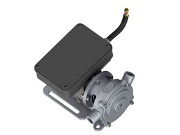
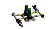
AFP - Another Fluid Pump: Airbus Challenge Winner design
by GrabCAD
Last crawled date: 1 year, 11 months ago
Please read AFP.pdf for following content
1. GENERAL INFORMATION
2. INTRODUCTION
3. SPECIFICATIONS OF PARTS AND MATERIAL
4. DETAIL DESCRIPTION
5. BLOCKED FLOW HANDLING METHOD
6. COST EFFECTIVENESS
7. INSTALLATION PROCESS
8. BILL OF MATERIAL
9. DRAWINGS
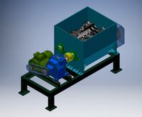
A ".STEP" model is uploaded to give the overview of assembly. All the part files are present in 'files' folder. Fasteners are not uploaded. The list of fasteners used is present in bill of material in AFP.pdf
GENERAL INFORMATION:
DIRECTION OF MOTION: Anti-Clockwise
SIZE: (l x b x h)
100 x 77x 60 mm^3 (including Box)
100 x 60 x 52 mm^3 (excluding Box)
MASS: 897.12 ± 50 grams (excluding Electronic Box)
SPACE FOR ELECTRONICS: 70 x 50 x 15 mm^3
ANGULAR VELOCITY REQUIRED FOR 7 L/MIN FLOW RATE = 1825.57 RPM
ANGULAR VELOCITY REQUIRED FOR 11 L/MIN FLOW RATE = 2868.76 RPM
OPERATING TEMPERATURE: The pump can operate between the temperature range from -20°C to 100°C provided there is no phase change of fluid. Also, it can sustain frequent thermal shift between above temperature range.
BLOCKED FLOW HANDLING METHOD: Mechanical and Electronic both
INLET OUTLET DIAMETER: 10 mm
The AFP pump is designed based on the phenomenon of Rotary Vane pump. The assembly is designed as per the regulation of CS 29 amdt 3. Following CS 29 amdt 3 general criteria, all the material used in designing the parts are accepted by European Aviation Safety Agency. Additionally, no sharp edges are exposed, all the fasteners are locked and no self-locking fasteners are used. The assembly is able to withstand up to -20 to 100 degree Celsius provided electronics and electronic box has the equivalent capability.
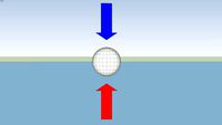
BLOCKAGE HANDLING
Let T be the force excreted by fluid on incline portion.
Therefore, t’ force is tending to push the rod in upward direction.
As the ROTOR is rotating with angular velocity, say W, then force exerted by BLADE is
F= mrW^2 where m, r is mass, radius
The reaction force exerted by BLADE on fluid is more than t’’.
Now, if the flow is blocked, then force exerted by Fluid is T’’, thereby T’’ >>> T
Simultaneously, the F will be reduced since W is decreased.
This leads to the upward movement of BLADES.
When the BLADES move upward, the T reduces. This let the movement of ROTOR to regain the speed. By regaining the speed, the F increases. Over all, it achieves the equilibrium position under Blocked flow circumstances.
Equilibrium condition F = T’’× sine(theta)
ADVANTAGES OF THIS METHOD
• This method of tackling the blocked flow is advantageous over electronic cut-off since this restart the flow of liquid immediately after the blockage is removed.
• Electronic cut-off switches the DC Motor off when the value of current exceeds the limited value. Though this prevents the damage, but reduces the life of motor and electronic circuit.
• This method is more reliable since it does not damage or force stops any component.
• Mechanical and electronics both constitute double blockage handling system, which is better than single one.
• Adds all the advantages of Rotary Vane Pump.
COST EFFECTIVENESS
• Vane Rotary pump is known for its complexities and huge assembly. However, here I have designed the parts like ROTOR CLAMPS, Bronze Bushes, BOX STAND which can be easily produced by simple machining operations.
• The parts that are manufactured by die (extrusion process) like MOTOR STAND, PUMP CASE, PUMP CASING CAP, MOTOR BACK SUPPORT have simple geometry, which reduces the cost of Die to minimum level.
• The thickness of wall for the casting and molding processes is kept at optimum level. This ensures that metal flow is uniform and chances of error reduce. This results in more efficient production line.
• As it was mandatory to follow the materials list used in Aviation process, the cost for preparing the structure by Aluminum proved more economical than High Quality Plastic material, which is used in aviation.
• Metal molding is more economical than plastic molding for smaller batch of product.
• Design of the ROTOR is done in the way that it does not require sophisticated tools to make. Also, the Die required for Permanent die casting is very simple, which reduces the overall cost of product.
• The use of sheet metal process to make BOX STAND adds to the cost cutting factor, and the MARKING PLATE can also be produced in bulk for future dates in a single go.
• The designing of the pump is done in segments to make sure there isn’t any complex cost draining part.
1. GENERAL INFORMATION
2. INTRODUCTION
3. SPECIFICATIONS OF PARTS AND MATERIAL
4. DETAIL DESCRIPTION
5. BLOCKED FLOW HANDLING METHOD
6. COST EFFECTIVENESS
7. INSTALLATION PROCESS
8. BILL OF MATERIAL
9. DRAWINGS
A ".STEP" model is uploaded to give the overview of assembly. All the part files are present in 'files' folder. Fasteners are not uploaded. The list of fasteners used is present in bill of material in AFP.pdf
GENERAL INFORMATION:
DIRECTION OF MOTION: Anti-Clockwise
SIZE: (l x b x h)
100 x 77x 60 mm^3 (including Box)
100 x 60 x 52 mm^3 (excluding Box)
MASS: 897.12 ± 50 grams (excluding Electronic Box)
SPACE FOR ELECTRONICS: 70 x 50 x 15 mm^3
ANGULAR VELOCITY REQUIRED FOR 7 L/MIN FLOW RATE = 1825.57 RPM
ANGULAR VELOCITY REQUIRED FOR 11 L/MIN FLOW RATE = 2868.76 RPM
OPERATING TEMPERATURE: The pump can operate between the temperature range from -20°C to 100°C provided there is no phase change of fluid. Also, it can sustain frequent thermal shift between above temperature range.
BLOCKED FLOW HANDLING METHOD: Mechanical and Electronic both
INLET OUTLET DIAMETER: 10 mm
The AFP pump is designed based on the phenomenon of Rotary Vane pump. The assembly is designed as per the regulation of CS 29 amdt 3. Following CS 29 amdt 3 general criteria, all the material used in designing the parts are accepted by European Aviation Safety Agency. Additionally, no sharp edges are exposed, all the fasteners are locked and no self-locking fasteners are used. The assembly is able to withstand up to -20 to 100 degree Celsius provided electronics and electronic box has the equivalent capability.
BLOCKAGE HANDLING
Let T be the force excreted by fluid on incline portion.
Therefore, t’ force is tending to push the rod in upward direction.
As the ROTOR is rotating with angular velocity, say W, then force exerted by BLADE is
F= mrW^2 where m, r is mass, radius
The reaction force exerted by BLADE on fluid is more than t’’.
Now, if the flow is blocked, then force exerted by Fluid is T’’, thereby T’’ >>> T
Simultaneously, the F will be reduced since W is decreased.
This leads to the upward movement of BLADES.
When the BLADES move upward, the T reduces. This let the movement of ROTOR to regain the speed. By regaining the speed, the F increases. Over all, it achieves the equilibrium position under Blocked flow circumstances.
Equilibrium condition F = T’’× sine(theta)
ADVANTAGES OF THIS METHOD
• This method of tackling the blocked flow is advantageous over electronic cut-off since this restart the flow of liquid immediately after the blockage is removed.
• Electronic cut-off switches the DC Motor off when the value of current exceeds the limited value. Though this prevents the damage, but reduces the life of motor and electronic circuit.
• This method is more reliable since it does not damage or force stops any component.
• Mechanical and electronics both constitute double blockage handling system, which is better than single one.
• Adds all the advantages of Rotary Vane Pump.
COST EFFECTIVENESS
• Vane Rotary pump is known for its complexities and huge assembly. However, here I have designed the parts like ROTOR CLAMPS, Bronze Bushes, BOX STAND which can be easily produced by simple machining operations.
• The parts that are manufactured by die (extrusion process) like MOTOR STAND, PUMP CASE, PUMP CASING CAP, MOTOR BACK SUPPORT have simple geometry, which reduces the cost of Die to minimum level.
• The thickness of wall for the casting and molding processes is kept at optimum level. This ensures that metal flow is uniform and chances of error reduce. This results in more efficient production line.
• As it was mandatory to follow the materials list used in Aviation process, the cost for preparing the structure by Aluminum proved more economical than High Quality Plastic material, which is used in aviation.
• Metal molding is more economical than plastic molding for smaller batch of product.
• Design of the ROTOR is done in the way that it does not require sophisticated tools to make. Also, the Die required for Permanent die casting is very simple, which reduces the overall cost of product.
• The use of sheet metal process to make BOX STAND adds to the cost cutting factor, and the MARKING PLATE can also be produced in bulk for future dates in a single go.
• The designing of the pump is done in segments to make sure there isn’t any complex cost draining part.
Similar models
grabcad
free

Centrifugal Pump
...ned to constrict the fluid from the pump inlet, direct it into the impeller and then slow and control the fluid before discharge.
grabcad
free

Impeller for centrifugal pump
...e and flow of a fluid. it is the opposite of a turbine, which extracts energy from, and reduces the pressure of, a flowing fluid.
grabcad
free

Impeller
...inlet to accept incoming fluid, vanes to push the fluid radially, and a splined, keyed, or threaded bore to accept a drive-shaft.
grabcad
free

Water Pump
...t, direct it into the impeller and then slow and control the fluid before discharge.
centrifugal pump specification: 125-100-250
grabcad
free

Rechargeable Table Fan
...of vanes or blades which act on the fluid. the rotating assembly of blades and hub is known as an impeller, a rotor, or a runner.
grabcad
free

PUMP IMPELLER
...e and flow of a fluid. it is the opposite of a turbine, which extracts energy from, and reduces the pressure of, a flowing fluid.
grabcad
free

Aviation Turbine Pump Impeller Blades
...rabcad
aviation turbine pump impeller blades designed at specific angular intervals for max efficiency and light weight profile.
3dwarehouse
free
Ballast Model
...odel
3dwarehouse
original model by superman. ballast is the upward force that a fluid exerts on an object less dense than itself
grabcad
free

Turbine blade
... wheel or rotor, typically fitted with vanes, is made to revolve by a fast-moving flow of water, steam, gas, air, or other fluid.
grabcad
free

Rotor vane pump
...p
grabcad
this is a model of rotor vane pump, the shaft and vanes are movable. remove the back cover to view the inner assembly.
Afp
thingiverse
free
Stem Adapter for Cuisinart AFP-7STM by ski
... me as is. if you need to adjust a parameter to improve the fit, easily open it up in the customizer app. measurements are in mm.
thingiverse
free

AFPS Another Foldable Phone Stand by MrWhitey
...ws:
1x m3x10 or max. m3x15 for the leg.stl connecting internal.stl
2x m3x10 or max. 2x m3x25 for the body connecting internal.stl
thingiverse
free

Custom Whoop Garage for Stanley Multi level orginizer
....for more info on the case watch this video https://youtu.be/afp2ozc2bu ...
thingiverse
free

Guantanamo Bay Prison Key by JeremyRuhland
...key seen in this photo by paul j. richards, afpgetty images http://www.canada.com/story_print.html?id=2043864 although it certainly doesn't fit into a...
grabcad
free

РЕГУЛИРУЩИЙ БЛОК AFP DANFOSS
...регулирущий блок afp danfoss
grabcad
регулирущий блок afp danfoss для клапана vfg2
grabcad
free

РЕГУЛИРУЩИЙ БЛОК С МЕМБРАНОЙ AFP-2 DANFOSS
...регулирущий блок с мембраной afp-2 danfoss
grabcad
регулирущий блок с мембраной afp-2 danfoss для клапан vfg22
grabcad
free

КЛАПАН СЕДЕЛЬНЫЙ VFG2 PN16 DANFOSS
...vfg2 pn16 danfoss устанавливается с регулирущими блоками с мембраной afpafpa,afa,afd/ ...
cg_trader
$4

Melee and Staff Weapons Greater Good | 3D
...good battlesuits. greater good space communist weapon melee sword afp cyclic fusion flamer burst miniatures sci fi sci...
cg_trader
$3
Weapons and Systems Greater Good | 3D
...greater good space communist weapon system fusion cyclic ion afp plasma flamer missile miniatures sci fi sci...
Winner
turbosquid
$10

Winner Cup
...ty free 3d model winner cup for download as obj, c4d, and fbx on turbosquid: 3d models for games, architecture, videos. (1475425)
3ddd
$1

Бильярдный стол Winner
... стол
бильярдный стол winner
американский пул.
производитель (или поставщик :) ) фирма "игра", г.москва
turbosquid
$10

Winner Trophy
... available on turbo squid, the world's leading provider of digital 3d models for visualization, films, television, and games.
turbosquid
$98
boxer winner ,pugile
...yalty free 3d model boxer winner ,pugile for download as stl on turbosquid: 3d models for games, architecture, videos. (1247091)
turbosquid
$15

Trophy for Winner and Champignons
... for winner and champignons for download as max, fbx, and obj on turbosquid: 3d models for games, architecture, videos. (1583314)
3d_export
$7

wreath of the winner
... edges: 450,007 facet: 300,031 tris: 300,031 verts: 44,966 edges: 135,281 facet: 90,187 tris: 90,187 need a change? write to mail
turbosquid
$1

Winner's Cup II
... available on turbo squid, the world's leading provider of digital 3d models for visualization, films, television, and games.
turbosquid
$19

Winner Skull Jewel Pendant
... model winner skull jewel pendant for download as obj and stl on turbosquid: 3d models for games, architecture, videos. (1614230)
turbosquid
$10

Moll Basic. Written Table Winner
... available on turbo squid, the world's leading provider of digital 3d models for visualization, films, television, and games.
cg_studio
$10

Golden Champion Cup Winner 23d model
...ory
.obj .fbx .max .3ds - golden champion cup winner 2 3d model, royalty free license available, instant download after purchase.
Fluid
turbosquid
free
Fluid(Fluid/Flow)
... available on turbo squid, the world's leading provider of digital 3d models for visualization, films, television, and games.
3ddd
$1
fluid
... вода , раковина , унитаз
сантехника_fluid
turbosquid
$3

correction fluid
...d
royalty free 3d model correction fluid for download as 3ds on turbosquid: 3d models for games, architecture, videos. (1148772)
turbosquid
$25

Fluid-sofa
... available on turbo squid, the world's leading provider of digital 3d models for visualization, films, television, and games.
turbosquid
$22
Fluid Tank
...odel fluid tank for download as obj, fbx, blend, dae, and stl on turbosquid: 3d models for games, architecture, videos. (1335082)
3ddd
$1
Softline Fluid 274
...e , fluid
высота (см) - 65
высота седалища (см) - 30
глубина (см) - 105
длина (см) - 160
turbosquid
$5

Mana Potion Fluid
...
royalty free 3d model mana potion fluid for download as c4d on turbosquid: 3d models for games, architecture, videos. (1366155)
3d_export
$20
fluid crystal
...fluid crystal
3dexport
it is a one-man electric car, part of its components are made of glass
turbosquid
$40

SUN with fluid anim
... free 3d model sun with fluid anim for download as ma and obj on turbosquid: 3d models for games, architecture, videos. (1480698)
3d_ocean
$4
Detail Fluid Splash
...id liquid miscelaneus splash
high quality liquid splash generated with realflow and sculpted zbrush. comes in 3ds and obj models.
Airbus
3d_ocean
$29

Airbus-330
...airbus-330
3docean
airbus airbus-330 aircraft
this is a model of airbus-330, wish you like.
3d_export
$30

Airbus A380
...airbus a380
3dexport
airbus a380
3d_export
$17

AIRBUS A320
...airbus a320
3dexport
airbus a320
3d_export
$17

Airbus A320
...airbus a320
3dexport
airbus a320
3d_export
$17

Airbus A350
...airbus a350
3dexport
airbus a350
3d_export
$10

airbus-a320
...airbus-a320
3dexport
airbus-a320
3d_ocean
$29

Airbus-380
...iner manufactured by airbus. it is the world’s largest passenger airliner, and the airports at which it operates have upgraded...
turbosquid
$99
airbus
... available on turbo squid, the world's leading provider of digital 3d models for visualization, films, television, and games.
turbosquid
$16

Airbus
... available on turbo squid, the world's leading provider of digital 3d models for visualization, films, television, and games.
3d_ocean
$9
AirBus
...nsport
low poly airbus model, modeled on cinema 4d r14,rendered by phisical sky render. including postproduction preset psd file.
Pump
3d_export
$5
pump
...pump
3dexport
pump
archibase_planet
free
Pump
...pump
archibase planet
petrol pump petrol station gas station
pump - 3d model (*.gsm+*.3ds) for interior 3d visualization.
3d_ocean
$8

Pumps
...ps
3docean
girls heels high kicks pumps shoes stilettos womens
womens high heels, pumps or stilettos. polygon model – no textures
3ddd
free
Pump
...ump
3ddd
pump , versus
производитель: versus
модель: pumphttp://www.versus.as/
turbosquid
$3
Pumps
...s
turbosquid
royalty free 3d model pumps for download as skp on turbosquid: 3d models for games, architecture, videos. (1275250)
3d_export
$5
pump
...pump
3dexport
turbosquid
$39
Realistic Water pump SYLLENT PUMP
...realistic water pump syllent pump for download as max and obj on turbosquid: 3d models for games, architecture, videos. (1312864)
turbosquid
$150

Pumpe
...yalty free 3d model pumpe for download as ige, blend, and stl on turbosquid: 3d models for games, architecture, videos. (1284318)
3d_export
$10
gear pump
...gear pump
3dexport
it is a gear pump in iges format
turbosquid
$19
Old Water Pumps Gas Pumps
...pumps gas pumps for download as 3ds, obj, fbx, blend, and dae on turbosquid: 3d models for games, architecture, videos. (1207997)
Challenge
turbosquid
$120
Challenger 2 and challenger 2 TES
...e 3d model challenger 2 and challenger 2 tes for download as on turbosquid: 3d models for games, architecture, videos. (1430319)
3d_export
$59
dodge challenger srt8
...dodge challenger srt8
3dexport
dodge challenger srt8
3d_export
$20
dodge challenger 1970
...dodge challenger 1970
3dexport
dodge challenger 1970
3d_export
$15
Dodge Challenger Hellcat
...dodge challenger hellcat
3dexport
dodge challenger hellcat
turbosquid
$80
challenger-2
...rbosquid
royalty free 3d model challenger-2 for download as on turbosquid: 3d models for games, architecture, videos. (1498848)
3d_export
$5

dodge challenger car
...dodge challenger car
3dexport
3d model dodge challenger!
turbosquid
$99
Dodge Challenger
...
royalty free 3d model dodge challenger for download as blend on turbosquid: 3d models for games, architecture, videos. (1489358)
turbosquid
$49
Dodge Challenger
...
royalty free 3d model dodge challenger for download as blend on turbosquid: 3d models for games, architecture, videos. (1698375)
turbosquid
$10
dodge challenger
...
royalty free 3d model dodge challenger for download as blend on turbosquid: 3d models for games, architecture, videos. (1405948)
3d_export
free
dodge challenger srt8
...dodge challenger srt8
3dexport
dodge challenger srt8 free model
Another
turbosquid
$15
ANOTHER BATHROOM
...quid
royalty free 3d model another bathroom for download as on turbosquid: 3d models for games, architecture, videos. (1171460)
turbosquid
$24

Another World
... available on turbo squid, the world's leading provider of digital 3d models for visualization, films, television, and games.
turbosquid
$39
Another Red Curb
...ee 3d model another red curb for download as ma, obj, and fbx on turbosquid: 3d models for games, architecture, videos. (1182913)
turbosquid
$9

Another Deberenn Sofa
...model another deberenn sofa for download as max, obj, and fbx on turbosquid: 3d models for games, architecture, videos. (1497850)
turbosquid
$2

Another picnic table
... model another picnic table for download as max, obj, and fbx on turbosquid: 3d models for games, architecture, videos. (1426381)
turbosquid
$15

door to another world
...oor to another world for download as 3ds, obj, fbx, and blend on turbosquid: 3d models for games, architecture, videos. (1334842)
3d_export
free
another hacksaw
...another hacksaw
3dexport
. . . 3d model of a hacksaw. 3d model files: - 3ds max 2017 (scanline) - obj (low poly) . . .
turbosquid
$12

Another Country Side Table
... another country side table for download as max, obj, and fbx on turbosquid: 3d models for games, architecture, videos. (1496053)
turbosquid
$29

Furniture - "Another country" modern sofa
...another country" modern sofa for download as obj and c4d on turbosquid: 3d models for games, architecture, videos. (1186189)
3d_ocean
$29

Another Tron Light Cycle with the Rider and Trail
...ther tron light cycle with the rider and the light trail. high quality 3d model,all the materials and lights are included. the...
Design
3ddd
$1
LINE DESIGN (Doors Design)
...line design (doors design)
3ddd
дверь
modern doors design - line design concept
turbosquid
$5

designer
...alty free 3d model designer for download as max, obj, and fbx on turbosquid: 3d models for games, architecture, videos. (1422665)
3ddd
$1

VER DESIGN
...ver design
3ddd
ver design
кресло ver design
3ddd
$1

VER DESIGN
...ver design
3ddd
ver design
диван ver design
3ddd
$1
Bagno design
...bagno design
3ddd
bagno design , унитаз
санитария bagno design
3ddd
free

VER DESIGN
...ver design
3ddd
ver design , стеллаж
полка ver design
3ddd
$1
VER DESIGN
...ver design , лежак , шезлонг
шезлонг ver design
3d_export
free

designer
..., trees and much more. the model has 3 types of parts: - 4 cells - 6 cells - 8 cells the *.max file contains 5 colored materials.
3d_export
$19
level design
...level design
3dexport
you can use this design (level design) in your own game.
3d_export
$7
Crusher design
...crusher design
3dexport
crusher design