Thingiverse
Advanced Delta Printer Calibration (tower position + individual diagonal rod) by dolpin
by Thingiverse
Last crawled date: 2 years, 12 months ago
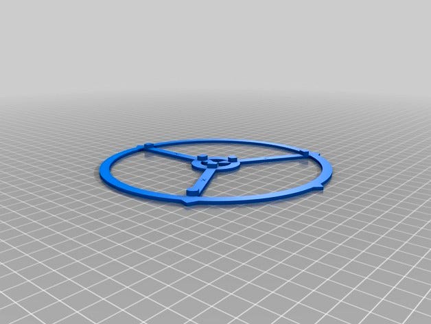
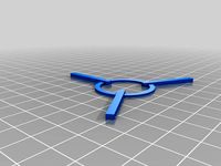
This calibration object will help you to calibrate angle and size errors on your delta 3d printer
These errors are typically caused by tower position errors and different diagonal rod lengths.
This calibration object will show if your printer suffers from sizing and angle errors and the instructions will help to solve these errors.
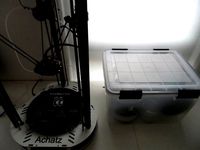
My Achatz easyDelta printer had a 1 degree error in angles and over 1mm error in sizing in certain directions. This is caused by the towers not being positioned at a perfect 120 degree angle around the center, and small individual size errors between the rods.
First errors must be fixed on the printer itself, but on some printers this might not be possible.
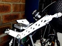
I used a jig to glue the joints to the diagonal rods, but small errors (1/10 mm) result in bigger errors in the print.
The basic delta printer calibration steps are:
calibrate the print bed on each tower position by adjusting the z-height for each carriage
correct for bowl/dome shape by adjusting the DELTA_RADIUS parameter
tune the print size by adjusting the DIAGONAL_ROD parameter
After the basic calibration you might experience that the actual print is not equal sized in all directions and the angles in all directions are not as they should be. Resulting in for instance trapezoid objects instead of square-angle objects.
The next calibration step is to detect these errors and calibrate your printer.
These errors are typically caused by tower misplacement and differences in diagonal rod length.
After calibrating the tower angles and individual diagonal rod lengths using the marlin firmware, I managed to achieve 0 degree angle error and a maximum of 0.1 mm size error in any direction in the print !
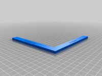
The calibration object is printed after the basic calibration. Print out the calibration sheet and use this sheet to measure the angles between the X-Y-Z towers. Use a slide caliper to measure the print size in the X-Y-Z tower direction and calibrate your printer in the Marlin firmware.
Check the instructions for the calibration steps and how to correct this.
These errors are typically caused by tower position errors and different diagonal rod lengths.
This calibration object will show if your printer suffers from sizing and angle errors and the instructions will help to solve these errors.
My Achatz easyDelta printer had a 1 degree error in angles and over 1mm error in sizing in certain directions. This is caused by the towers not being positioned at a perfect 120 degree angle around the center, and small individual size errors between the rods.
First errors must be fixed on the printer itself, but on some printers this might not be possible.
I used a jig to glue the joints to the diagonal rods, but small errors (1/10 mm) result in bigger errors in the print.
The basic delta printer calibration steps are:
calibrate the print bed on each tower position by adjusting the z-height for each carriage
correct for bowl/dome shape by adjusting the DELTA_RADIUS parameter
tune the print size by adjusting the DIAGONAL_ROD parameter
After the basic calibration you might experience that the actual print is not equal sized in all directions and the angles in all directions are not as they should be. Resulting in for instance trapezoid objects instead of square-angle objects.
The next calibration step is to detect these errors and calibrate your printer.
These errors are typically caused by tower misplacement and differences in diagonal rod length.
After calibrating the tower angles and individual diagonal rod lengths using the marlin firmware, I managed to achieve 0 degree angle error and a maximum of 0.1 mm size error in any direction in the print !
The calibration object is printed after the basic calibration. Print out the calibration sheet and use this sheet to measure the angles between the X-Y-Z towers. Use a slide caliper to measure the print size in the X-Y-Z tower direction and calibrate your printer in the Marlin firmware.
Check the instructions for the calibration steps and how to correct this.
Similar models
thingiverse
free
150x150 XY calibration
...t;upload" button.
ex) when the current x length is 151mm and the number of x steps is 81steps / mm.
(81 * 150) / 151 = 80.46
thingiverse
free

Kossel Delta Z axe calibration by Paxy
...kossel-mini-calibration)
change screw distancers of each tower (that touch endstops) until you get same line width on all sides
thingiverse
free

multi axis delta printer diagonal calibration by rampico
... equals. if yes you are fine
5.if not, change the diagonals errors in the firmware (or eeprom) using some proportion....
6.goto 2
thingiverse
free

CoreXY Motor Calibration by pizzachef
...e a single xy motor moves the print head on a 45 degree angle, the length of the sides is determined by isolated motor movements.
thingiverse
free

Delta printer calibration test disc by torsti76
...delta_diagonal_rod_trim_tower_... is currently undocumented in marlin (cf. https://github.com/marlinfirmware/marlin/issues/2159).
thingiverse
free
Delta printer calibration (size of the print) step per mm by Bob-In
...rial enough clear ? what can i change or add to make it better ?
is that helped ? not enough ? do it again and again until it is
thingiverse
free
Parametized Container by thevisad
...ored connected plane.
the delta top object is actually a design that will fit ontop of a delta tower and create an enclosed top.
thingiverse
free

Kossel Mini Printed Diagonal rods for Traxxas 5347 rod ends. by twelvepro
...ods for delta printers using traxxas 5347
rod ends.
after attaching rod ends you will have 250mm from hole to hole
diagonal rods.
thingiverse
free

Delta angle and Z plane calibration by alextien
...23
you can check delta three tower angles and z plane flatness with single file.
for angle calibration, check source instruction.
thingiverse
free

Kossel / Delta Dimensional Calibration with Instructions by Coffea
...s created a remix of this with accompanying spreadsheet to calibrate cartesian printers https://www.thingiverse.com/thing:2390274
Dolpin
turbosquid
$50
Humidifier of Dolpin type
... available on turbo squid, the world's leading provider of digital 3d models for visualization, films, television, and games.
thingiverse
free

5" monitor sunshade by dolpin
...hade is made for an unbranded 5" 5.8ghz monitor.
the clip makes it easy to attach and remove the sunshade from the monitor
thingiverse
free

Achatz easyDelta platform with fan by dolpin
...replace the original easydelta printer platform to add 2x 30mm material cooling ventilators and to lock an e3d v6 hotend in place
thingiverse
free

EC5 connector safety caps by dolpin
...se metal lying around. i feel more comfortable carrying these batteries around in a lipo-safe bag using a cap over the connector.
thingiverse
free
Spool Holder Prusa Mendel i2 Remix of dolpin's design by cptcupcake
...mendel i2 remix of dolpin's design by cptcupcake
thingiverse
this spool holder replaces the clamps that hold the z axis rods
thingiverse
free

garmin 400 serie (421) permanent bulkhead mount by dolpin
... 400 series chartplotter to a bulkhead.
a string can be attached between the cover (drill small hole in handle) and the fixture
thingiverse
free

Spring loaded throttle for Spektrum DX6i transmitter by dolpin
...en the throttle stick is released
works ideal in combination with a naza flight controller when flying in attitude or gps mode.
thingiverse
free

easyDelta rigid frame by dolpin
...rews with a ring. a 4.5x30 wood screw can be used to attach the part of the bracket pointing towards the center to the top plate
thingiverse
free
simple spool holder Prusa Mendel i2 by dolpin
...70 x 140mm
15 dec 2013
incorporated slots for the spool holder rod instead of holes
reinforced the spool holder around the bend
thingiverse
free
Airtight filament container / box by dolpin
...e the filament connected to the extruder and still keep the rol of filament inside the airtight 'low humidity' container.
Diagonal
3ddd
$1
Natuzzi / DIAGONAL
... natuzzi , угловой
диван diagonal фирмы natuzzi
3ddd
$1

Diagonal Fendi casa 2014
... 2014
3ddd
diagonal , fendi casa
диван коллекции diagonal производство fendi casa, 2014
turbosquid
$30

Tomasella Diagonal sideboard
...odel tomasella diagonal sideboard for download as max and fbx on turbosquid: 3d models for games, architecture, videos. (1192809)
turbosquid
$12

Feltouch diagon Screen
...e 3d model feltouch diagon screen for download as 3ds and max on turbosquid: 3d models for games, architecture, videos. (1444600)
turbosquid
$2
Diagonal striped box
... available on turbo squid, the world's leading provider of digital 3d models for visualization, films, television, and games.
design_connected
$13
Bois de Rose diagonal
...bois de rose diagonal
designconnected
edra bois de rose diagonal computer generated 3d model. designed by morozzi, massimo.
3ddd
free

rancesko Molon P501 armchair DIAGONAL
...r diagonal
3ddd
francesco molon , francesko molon
francesko molon p501 armchair diagonal
turbosquid
$12

Diagonal Wall Library Shelves
...del diagonal wall library shelves for download as max and fbx on turbosquid: 3d models for games, architecture, videos. (1619963)
3ddd
free

rancesko Molon S501 ottoman DIAGONAL
... капитоне , пуф
francesko molon s501 ottoman diagonal
turbosquid
$4
Habitarte Diagonal Wall form
...abitarte diagonal wall form for download as max, fbx, and obj on turbosquid: 3d models for games, architecture, videos. (1596572)
Calibration
turbosquid
$15
DEFIBRILLATOR CALIBRATORS
... available on turbo squid, the world's leading provider of digital 3d models for visualization, films, television, and games.
turbosquid
$3
Calibration Test Benches
...libration test benches for download as 3ds, obj, c4d, and fbx on turbosquid: 3d models for games, architecture, videos. (1355804)
turbosquid
$50
Smith & Wesson 50 Calibre Magnum
... available on turbo squid, the world's leading provider of digital 3d models for visualization, films, television, and games.
3d_export
$10
Laboratory Calibration Weight Set 1 3D Model
... 3d model
3dexport
laboratory lab science equipment weight set
laboratory calibration weight set 1 3d model bessoo 88084 3dexport
3d_export
$15
Laboratory Scale and Calibration Weight Set 3D Model
...port
laboratory lab science equipment weight set scale
laboratory scale and calibration weight set 3d model bessoo 88203 3dexport
3d_export
$5
3D printer filament calibration tool 3D Model
...ernier
3d printer filament calibration tool 3d model download .c4d .max .obj .fbx .ma .lwo .3ds .3dm .stl locoman 107942 3dexport
3d_export
$59
tag heuer link calibre 16 watch
...built to real-world scale. units used: centimeters. model is 18 centimeters tall.<br>scene objects are organized by groups.
3d_export
free
laser height reference calibration tool opt lasers
...ind out more about the engraving and cutting laser heads, this item was designed to work with, take a look at the following page:
3d_export
$99
Patek Philippe White Gold Calibre 89
...br>please note: this 3d model like all my other models cannot be used as nft, as is or modified<br>thank you for reading
archive3d
free
Modulor 3D Model
...modulor 3d model
archive3d
modulor standard calibrating device
Delta
design_connected
$16

Delta
...delta
designconnected
lj lamps delta computer generated 3d model. designed by janowski-lenhart, sasha.
design_connected
$16
Delta
...delta
designconnected
arflex international spa delta computer generated 3d model. designed by koivisto, eero.
design_connected
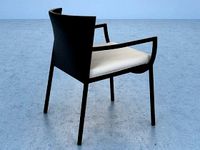
$13
Delta
...delta
designconnected
emu group delta armchairs computer generated 3d model. designed by marin chiaramonte .
3ddd
$1
Delta Light
...delta light
3ddd
delta light , you-turn reo 3033
точечний светильник delta light
3ddd
$1
Blanco / delta
...blanco / delta
3ddd
blanco , мойка
мойка blanco delta со смесителем
3ddd
$1
Delta Light Spot
...delta light spot
3ddd
delta light
светильник фирмы delta light
3ddd
free
Bianchi Delta LVMDLT200100
...i delta lvmdlt200100
3ddd
bianchi delta , смеситель
смеситель bianchi delta lvmdlt200100
design_connected
free
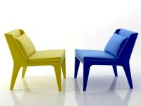
Delta 190
...delta 190
designconnected
free 3d model of delta 190 by zanotta designed by progetti, emaf.
design_connected
$27
Delta 211
...delta 211
designconnected
zanotta delta 211 computer generated 3d model. designed by progetti, emaf.
design_connected
$27

Delta 234
...delta 234
designconnected
zanotta delta 234 computer generated 3d model. designed by progetti, emaf.
Advanced
turbosquid
$139
Carol (Advanced)
... available on turbo squid, the world's leading provider of digital 3d models for visualization, films, television, and games.
turbosquid
$15
ADVANCED ROOM.max
... available on turbo squid, the world's leading provider of digital 3d models for visualization, films, television, and games.
turbosquid
$15

Explay Advance
... available on turbo squid, the world's leading provider of digital 3d models for visualization, films, television, and games.
turbosquid
$2

Advanced Crate
... available on turbo squid, the world's leading provider of digital 3d models for visualization, films, television, and games.
turbosquid
$1
Advanced Canister
... available on turbo squid, the world's leading provider of digital 3d models for visualization, films, television, and games.
turbosquid
$20

automatic Advance Gun
...
royalty free 3d model automatic advance gun for download as on turbosquid: 3d models for games, architecture, videos. (1609069)
turbosquid
$4

Advanced Shower Equipment
...free 3d model advanced shower equipment for download as blend on turbosquid: 3d models for games, architecture, videos. (1282411)
turbosquid
$1

Advanced Sniper Rifle
...oyalty free 3d model advanced sniper rifle for download as obj on turbosquid: 3d models for games, architecture, videos. (720205)
3d_ocean
$32
Advanced Hospital Bed
...ds max 2010 or higher and many others. formats *.max scanline *.max vray *.max mentalray *.c4d advanced render *.c4d cinema 4d...
turbosquid
$17

Advance Rifle Patrol
...free 3d model advance rifle patrol for download as ma and obj on turbosquid: 3d models for games, architecture, videos. (1409260)
Individual
turbosquid
$29

Individual House
...e 3d model individual house for download as 3ds, c4d, and fbx on turbosquid: 3d models for games, architecture, videos. (1253255)
3d_ocean
$21
Loewe Individual TV
...ddot screen tv
3d model of loewe individual tv in 5 variations. rendered with vray. thank you! please see some of my collection…
3d_ocean
$19
3D Individual house
...d model of a small 2 levels individual house, featuring all the détails from doors to windows, with a very detailed shingle roof.
3ddd
$1
Individual Reception
...individual reception
3ddd
ресепшн
стойка-ресепшен, выполненная для уже осуществленного проекта интерьера холла гостиницы
turbosquid
$30

Individual Guarding Angel
...el individual guarding angel for download as ma, max, and fbx on turbosquid: 3d models for games, architecture, videos. (1200759)
3d_export
$15

The individual ring 3D Model
...the individual ring 3d model
3dexport
the individual ring 3d model wintik174 96479 3dexport
design_connected
free

TV Individual 52 Compose
...tv individual 52 compose
designconnected
free 3d model of tv individual 52 compose by loewe
3d_export
$20
Loewe individual 3D Model
...loewe individual 3d model
3dexport
tv video television телевизор тв
loewe individual 3d model salamb86 34311 3dexport
3d_export
$15

The individual ring 1 3D Model
...the individual ring 1 3d model
3dexport
the individual ring 1 3d model wintik174 96480 3dexport
turbosquid
$2

Transparent Thumbtacks (Individual and in Cases)
... available on turbo squid, the world's leading provider of digital 3d models for visualization, films, television, and games.
Rod
archibase_planet
free
Rod
...rod
archibase planet
shank rod
so rod - 3d model (*.gsm+*.3ds) for interior 3d visualization.
archibase_planet
free

Spinning rod
...g rod
archibase planet
spinning rod spinning rod fishing-rod
spinning rod - 3d model (*.gsm+*.3ds) for interior 3d visualization.
3d_export
$5
rod handle
...rod handle
3dexport
rod handle
3ddd
$1
bench with rods
...bench with rods
3ddd
скамейка
bench with rods
3ddd
$1
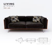
диван ROD
...диван rod
3ddd
rod , living divani
http://www.livingdivani.it/
3ddd
$1
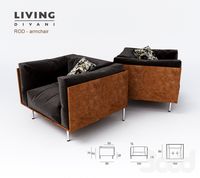
кресло ROD
...кресло rod
3ddd
rod , living divani
http://www.livingdivani.it/
design_connected
$18
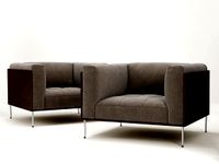
Rod Armchair
...rod armchair
designconnected
living divani rod armchair computer generated 3d model. designed by lissoni, piero.
archive3d
free

Rod 3D Model
...rod 3d model
archive3d
shank rod
so rod - 3d model (*.gsm+*.3ds) for interior 3d visualization.
turbosquid
$15

Fishing rod
...urbosquid
royalty free 3d model fishing rod for download as on turbosquid: 3d models for games, architecture, videos. (1684756)
archive3d
free
Spinning rod 3D Model
...d spinning rod fishing-rod
spinning rod - 3d model (*.gsm+*.3ds) for interior 3d visualization.
Position
3ddd
$1

Moooi | Position
...moooi | position
3ddd
moooi , position profi
moooi position floor lamp
design_connected
$20
Pole Position
...e position
designconnected
l'abbate pole position armchairs computer generated 3d model. designed by luigi caccia dominioni.
3d_export
$5
six position riveting machine
...six position riveting machine
3dexport
six position riveting machine
3ddd
$1

Moooi Position wall lamp
...moooi position wall lamp
3ddd
moooi , position wall lamp
3ddd
free

Cilek, модель positive oak
...cilek, модель positive oak
3ddd
cilek
детская фирмы cilek, модель positive oak
turbosquid
$98

Coat in 6 positions
... available on turbo squid, the world's leading provider of digital 3d models for visualization, films, television, and games.
turbosquid
$39

Position of Gynoecium on the Thalmus
... available on turbo squid, the world's leading provider of digital 3d models for visualization, films, television, and games.
3d_ocean
$8

Female in anatomical position
...tration inside medical medicine muscular naked organ patient penis science spine thorax torso x-ray
female in anatomical position
3d_export
$7

positioning screw mechanism
...ve any questions also you can email to me.<br>designed with solidworks 2017<br>**************************************
turbosquid
$50

Three position bed Pillows
... available on turbo squid, the world's leading provider of digital 3d models for visualization, films, television, and games.
Tower
archibase_planet
free
Tower
...kremlin tower spasskaya tower
tower kremlin spasskaya tower n120615 - 3d model (*.gsm+*.3ds+*.max) for exterior 3d visualization.
archibase_planet
free
Tower
...r kremlin tower petrovskaya tower
tower petrovskaya kremlin n120615 - 3d model (*.gsm+*.3ds+*.max) for exterior 3d visualization.
archibase_planet
free
Tower
...ino-eleninskaya tower
tower constantino eleninskaya kremlin n120615 - 3d model (*.gsm+*.3ds+*.max) for exterior 3d visualization.
archibase_planet
free
Tower
...tower
archibase planet
tower statuette eiffel tower
tower decor n180914 - 3d model (*.gsm+*.3ds) for interior 3d visualization.
archibase_planet
free
Tower
...lanet
tower construction building
tower polices post street tower n110913 - 3d model (*.gsm+*.3ds) for exterior 3d visualization.
3d_export
$5

tower
...tower
3dexport
a fortified tower with a moat.
archibase_planet
free
Tower
...tower
archibase planet
building tower construction
tower n300712 - 3d model (*.gsm+*.3ds) for exterior 3d visualization.
archibase_planet
free
Tower
...uilding kremlin construction
tower 2 vtoraya bezymyannaya kremlin n100914 - 3d model (*.gsm+*.3ds) for exterior 3d visualization.
archibase_planet
free
Tower
...tower
archibase planet
forcetower tower
forcetower - 3d model for interior 3d visualization.
archibase_planet
free
Transmission tower
...lectricity pylon lattice tower framework tower
transmission tower n121015 - 3d model (*.gsm+*.3ds) for exterior 3d visualization.
Printer
archibase_planet
free
Printer
...inter
archibase planet
printer laser printer pc equipment
printer n120614 - 3d model (*.gsm+*.3ds) for interior 3d visualization.
archibase_planet
free
Printer
...rchibase planet
laser printer office equipment computer equipment
printer - 3d model (*.gsm+*.3ds) for interior 3d visualization.
turbosquid
$100
Printer
...er
turbosquid
royalty free 3d model printer for download as on turbosquid: 3d models for games, architecture, videos. (1487819)
turbosquid
$3
Printer
...turbosquid
royalty free 3d model printer for download as max on turbosquid: 3d models for games, architecture, videos. (1670230)
turbosquid
$1
printer
...turbosquid
royalty free 3d model printer for download as max on turbosquid: 3d models for games, architecture, videos. (1595546)
turbosquid
$1
printer
...turbosquid
royalty free 3d model printer for download as max on turbosquid: 3d models for games, architecture, videos. (1595105)
turbosquid
$10
Printer
...id
royalty free 3d model printer for download as max and 3dm on turbosquid: 3d models for games, architecture, videos. (1607146)
turbosquid
$7
Printer
...royalty free 3d model printer for download as ma, ma, and obj on turbosquid: 3d models for games, architecture, videos. (1644580)
turbosquid
$30
Printer
... available on turbo squid, the world's leading provider of digital 3d models for visualization, films, television, and games.
turbosquid
$20
Printer
... available on turbo squid, the world's leading provider of digital 3d models for visualization, films, television, and games.