Thingiverse
Adding MK3 heatbed to Vertex K8400 by Bo_Ris
by Thingiverse
Last crawled date: 3 years ago
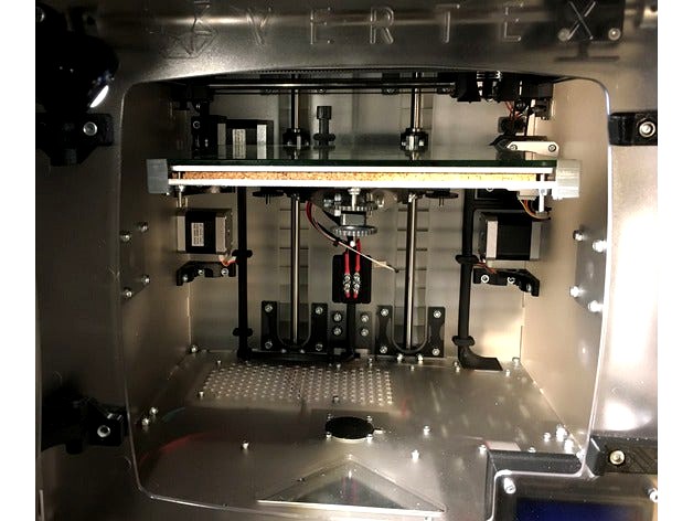
Adding heatbed to VERTEX K8400 is not as difficult as one may think. Here is the list of parts that I used:
MK3 heatbead
Velleman's 24VDC 150W power supply
3D Printer Heated Bed Power Module
NTC 3950 100K Thermistor with Wiring
Heat resistant silicon
Sheet of 5mm cork
Several M3 screws
Several 3d printed parts
I bought the parts from reprapchampion.com They have good prices and ship the same business day. I also purchased 2 pieces of Borosilicate Glass 219x219mm, but so far I was not able to find a good way to mount them on top of MK3, which is 220x220mm. That's why at the moment I'm using the original 4mm glass that came with K8400. Binder clips could be an option, but they take space and complicate glass installation and removal. Ideal solution would be to buy a bigger 3mm Borosilicate glass and cut it to the dimensions of the original glass (240mm x 215mm).
Attached Files
I am attaching several STL files, but the only one you really need is called corner.stl. Four corner things keep the original glass in place.
Corner.stl was designed to fit the "sandwich" of the original aluminum bed plate covered by 5mm cork sheet with MK3 heatbed on top of it.
side.stl thing stops the glass from side movement. It is optional, as the corner things do the same.
bottom_under.stl, top_center.stl, heatbed_connectors.stl, heatbed_connectors_cover.stl and bottom-center.stl files are for those who installed my wire covers posted here. Old wire covers need to be replaced to accommodate additional wires.
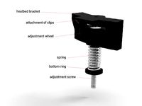
center_mount_bottom.stl, center_mount_TOP.stl and center_mount.stl things are mounted to the center of printer’s bottom panel. center_mount.stl houses Heated Bed Power Module and Raspberry Pi’s power supply board; I extracted it from Pi’s standard power supply. center_mount_TOP.stl is just a decorative piece that you can glue on top of center_mount.stl to cover the fan opening in bottom panel. center_mount_bottom.stl is the bottom cover for center_mount.stl. It also holds Raspberry Pi’s power supply board in place.
power_supply_safety.stl thing covers the connectors of 24VDC power supply, to protect user from accidentally touching them.
Wiring
You will need to add 5 sets of wires:
1) Connect AC power cord or power switch to newly added power supply (2 wires + ground wire)
2) Connect power supply to Printer Heated Bed Power Module (2 wires)
3) Connect Printer Heated Bed Power Module to MK3 bed (2 wires)
4) Connect thermistor attached to the heatbed to the mainboard (2 wires)
5) Connect mainboard to Printer Heated Bed Power Module (2 wires)
If you have Raspberry Pi mounted to the printer and want to move its power supply into center_mount.stl thing, you will need 2 additional sets of wires:
6) From AC power cord or power switch to Pi power supply card (2 wires) and
7) from Pi power supply card to Raspberry (2 wires)
How to run the wires is up to you. It will depend on where you install 24VDC power supply and power module, and if you want heatbed to be removable. I opted for the later and installed additional connectors for the wires going towards MK3. I used 2 Position Terminal Strip as 24VDC connector and 2 Pin 0.1" Polarized Locking Header for thermistor wires. They both are housed in center_mount.stl thing. Thermistor connector is soldered to a little piece of prototype board that slides into center_mount.stl thing from the back.
Assembly instructions
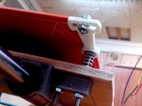
Start with gluing the thermistor into the center hole of MK3 with heat resistant silicon. It will take about 24 hours to completely dry.
Print all the things posted here, but do not change the position of Z-stop sensor. Drill the hole in aluminum bed plate as shown in the image from that post.
Drill 6 additional holes in the bed plate. 4 holes with 3.2mm diameter should be aligned with the mounting screw holes of MK3 (see image). Put MK3 on top of the bed plate, align it to be in the very center and mark 4 points to drill. 2 other holes with M3 thread inside are needed for front-left and rear-right glass holders. Bed plate already has similar holes in 2 other corners (see image).
Print 4 copies of corner.stl thing. ABS would be the preferred option. Use 0.2mm resolution.
Once all parts are available, start from locating the place where you mount 24VDC power supply. If you printed and intend to use cente_mount thing, install it temporarily and then find the place where you can fit 24VDC power supply. The way I mounted mine is shown on attached images. You will need to drill 4 holes in the bottom panel of the printer for M3 mounting screws. Use 5mm high spacers to keep distance between the power supply and printer’s bottom panel. Mounting screws should be M3 x 12mm.
Use four M3 x 6mm screws to mount heatbed power module to center_mount.stl thing. Raspberry Pi power supply board simply slides in and does not require screws.
Place MK3 on top of cork sheet and cut the cork along MK3 edges with sharp knife. Cut the “channel” in the cork along the thermostat wires. Cut the cork around MK3 soldering pads and mounting holes.
Put all things together as shown on the images. While installing wiring make sure to properly connect the positive and negative wires, where applicable. Use pads #2 and #3 to feed MK3 with 24VDC. If you purchased 12VDC power supply, connect pad #2 to pad #3 and feed 12V between these 2 pads and pad #1.
No firmware changes are required. Mainboard detects the presence of heatbed as soon as you connect heatbed thermistor to it.
Update 21-June-2017
Uploaded new revision of heatbed_connectors thing. Relocated thermostat connector and added cover.
Update 16-April-2018
Uploaded corner and side Things for 1mm thick heatbead.
MK3 heatbead
Velleman's 24VDC 150W power supply
3D Printer Heated Bed Power Module
NTC 3950 100K Thermistor with Wiring
Heat resistant silicon
Sheet of 5mm cork
Several M3 screws
Several 3d printed parts
I bought the parts from reprapchampion.com They have good prices and ship the same business day. I also purchased 2 pieces of Borosilicate Glass 219x219mm, but so far I was not able to find a good way to mount them on top of MK3, which is 220x220mm. That's why at the moment I'm using the original 4mm glass that came with K8400. Binder clips could be an option, but they take space and complicate glass installation and removal. Ideal solution would be to buy a bigger 3mm Borosilicate glass and cut it to the dimensions of the original glass (240mm x 215mm).
Attached Files
I am attaching several STL files, but the only one you really need is called corner.stl. Four corner things keep the original glass in place.
Corner.stl was designed to fit the "sandwich" of the original aluminum bed plate covered by 5mm cork sheet with MK3 heatbed on top of it.
side.stl thing stops the glass from side movement. It is optional, as the corner things do the same.
bottom_under.stl, top_center.stl, heatbed_connectors.stl, heatbed_connectors_cover.stl and bottom-center.stl files are for those who installed my wire covers posted here. Old wire covers need to be replaced to accommodate additional wires.
center_mount_bottom.stl, center_mount_TOP.stl and center_mount.stl things are mounted to the center of printer’s bottom panel. center_mount.stl houses Heated Bed Power Module and Raspberry Pi’s power supply board; I extracted it from Pi’s standard power supply. center_mount_TOP.stl is just a decorative piece that you can glue on top of center_mount.stl to cover the fan opening in bottom panel. center_mount_bottom.stl is the bottom cover for center_mount.stl. It also holds Raspberry Pi’s power supply board in place.
power_supply_safety.stl thing covers the connectors of 24VDC power supply, to protect user from accidentally touching them.
Wiring
You will need to add 5 sets of wires:
1) Connect AC power cord or power switch to newly added power supply (2 wires + ground wire)
2) Connect power supply to Printer Heated Bed Power Module (2 wires)
3) Connect Printer Heated Bed Power Module to MK3 bed (2 wires)
4) Connect thermistor attached to the heatbed to the mainboard (2 wires)
5) Connect mainboard to Printer Heated Bed Power Module (2 wires)
If you have Raspberry Pi mounted to the printer and want to move its power supply into center_mount.stl thing, you will need 2 additional sets of wires:
6) From AC power cord or power switch to Pi power supply card (2 wires) and
7) from Pi power supply card to Raspberry (2 wires)
How to run the wires is up to you. It will depend on where you install 24VDC power supply and power module, and if you want heatbed to be removable. I opted for the later and installed additional connectors for the wires going towards MK3. I used 2 Position Terminal Strip as 24VDC connector and 2 Pin 0.1" Polarized Locking Header for thermistor wires. They both are housed in center_mount.stl thing. Thermistor connector is soldered to a little piece of prototype board that slides into center_mount.stl thing from the back.
Assembly instructions
Start with gluing the thermistor into the center hole of MK3 with heat resistant silicon. It will take about 24 hours to completely dry.
Print all the things posted here, but do not change the position of Z-stop sensor. Drill the hole in aluminum bed plate as shown in the image from that post.
Drill 6 additional holes in the bed plate. 4 holes with 3.2mm diameter should be aligned with the mounting screw holes of MK3 (see image). Put MK3 on top of the bed plate, align it to be in the very center and mark 4 points to drill. 2 other holes with M3 thread inside are needed for front-left and rear-right glass holders. Bed plate already has similar holes in 2 other corners (see image).
Print 4 copies of corner.stl thing. ABS would be the preferred option. Use 0.2mm resolution.
Once all parts are available, start from locating the place where you mount 24VDC power supply. If you printed and intend to use cente_mount thing, install it temporarily and then find the place where you can fit 24VDC power supply. The way I mounted mine is shown on attached images. You will need to drill 4 holes in the bottom panel of the printer for M3 mounting screws. Use 5mm high spacers to keep distance between the power supply and printer’s bottom panel. Mounting screws should be M3 x 12mm.
Use four M3 x 6mm screws to mount heatbed power module to center_mount.stl thing. Raspberry Pi power supply board simply slides in and does not require screws.
Place MK3 on top of cork sheet and cut the cork along MK3 edges with sharp knife. Cut the “channel” in the cork along the thermostat wires. Cut the cork around MK3 soldering pads and mounting holes.
Put all things together as shown on the images. While installing wiring make sure to properly connect the positive and negative wires, where applicable. Use pads #2 and #3 to feed MK3 with 24VDC. If you purchased 12VDC power supply, connect pad #2 to pad #3 and feed 12V between these 2 pads and pad #1.
No firmware changes are required. Mainboard detects the presence of heatbed as soon as you connect heatbed thermistor to it.
Update 21-June-2017
Uploaded new revision of heatbed_connectors thing. Relocated thermostat connector and added cover.
Update 16-April-2018
Uploaded corner and side Things for 1mm thick heatbead.
Similar models
thingiverse
free

Bottom Corners for Delta kossel printer (Micromake D1) by vmzsoft
...istor and for bed control power module are laid through the holes of the vertical racks to top.
may be uses for anicubic and etc.
thingiverse
free
Raspberry pi case holder Ver.2 (power supply mount) by TK_DESIGN
...y pi case.http://www.thingiverse.com/thing:559858
it fits switching power supply.
type : width 113.4mm
m4 screw hole pitch 50.3mm
thingiverse
free

Anet A8 Power Supply Cover incl. fused C-14 power socket, 2 channel Relais and RS-15-5 5v Power supply by caesar_1111
...)
as always i included the freecad model.
caesar
ps: be careful when clipping in the rs-15-5 since the clips as somehow fragile.
thingiverse
free

Silicone Heat Bed Mount by clough42
...r configured correctly. it's very easy to reach very high temperatures (>150c) very quickly if you have it misconfigured.
thingiverse
free

PCB heated bed Mk3 by EiNSTeiN_
...has a spot for a surface mount right-angle led on the side of the bed instead of soldering a normal led facing down like the mk1.
grabcad
free

Aluminum extruded enclosure for Raspberry Pi
...rews to mount the pcb and covers. next, this enclosure has 2 fixation holes m3 at the bottom to mount optional mounting brackets.
thingiverse
free

Power Supply Cover for Anycubic Kossel Heated Bed Kits by carlbelcher
...: anycubic upgraded delta rostock 3d printer kossel kit large print size with heatbed and power supply
link: http://a.co/00tesek
thingiverse
free

Mount for camera module to the raspberry pi on the Mendel90 by Gotavi
...oid having to have a computer connected to 3d-printers.
bom:
plastic
1 camera module for raspberry pi
4 m3 10mm screv
3 led 5mm
thingiverse
free

Raspberry Pi 4 Argon One for Prusa MK3S+ by FrancPerez
...rinter or the inputs show to the top.
model base on:
raspberry pi case for prusa i3 / i3 mk2
raspberry pi 4 argon one wall mount
thingiverse
free

Raspberry Power Supply by Joeend11
...is: 5v 3a dc/dc converter with usb port, 7-24 input voltage kis3r33s step-down module. sellers may be found by any search engine.
K8400
thingiverse
free
Vertex K8400 Small Corner part (K8400-HQP-SC) by Hest
...vertex k8400 small corner part (k8400-hqp-sc) by hest
thingiverse
vertex k8400 small corner part (k8400-hqp-sc)
thingiverse
free

Base for K8400 by Hitty
...base for k8400 by hitty
thingiverse
just a base for your k8400 to extend the space for the power adapter.
thingiverse
free

K8400 Fan tool by dergringo
...k8400 fan tool by dergringo
thingiverse
k8400 fan tool
thingiverse
free
Support ventilateur K8400 / Fan support K8400 by ldellanna
........................
fan support for velleman vertex k8400
minimum layer : 0.2mm
printing time in 0.1mm -> max 20 minutes
thingiverse
free

K8400 Scraper holder by Storm67
...k8400 scraper holder by storm67
thingiverse
scraber holder for velleman k8400 vertex
thingiverse
free

Fan Tool K8400 Velleman by dergringo
...fan tool k8400 velleman by dergringo
thingiverse
fan tool velleman k8400
thingiverse
free

Endcap Custom for Vertex K8400 by olechristiandalseth
...endcap custom for vertex k8400 by olechristiandalseth
thingiverse
endcap for vertex k8400
left and right.
thingiverse
free
Vertex K8400 spool holder by simersion
...vertex k8400 spool holder by simersion
thingiverse
spoolholder for vertex k8400
100mm length and 35mm diameter.
thingiverse
free
E3D dual head K8400 by hexxter
...e3d dual head k8400 by hexxter
thingiverse
holder for the e3d hot end on the vertex k8400 printer.
thingiverse
free

Vertex K8400 power switch by Zannddor
...vertex k8400 power switch by zannddor
thingiverse
alternative power switch to the 3d printer vertex k8400
Ris
turbosquid
$20

ris
... available on turbo squid, the world's leading provider of digital 3d models for visualization, films, television, and games.
3ddd
$1

Лампа Настольная Vita Ri 22163
...лампа настольная vita ri 22163
3ddd
vita , ri
лампа настольная vita ri 22163
3ddd
$1

Кресло JUMBO RIS-41b
...hymia
стиль: классика
длина: 80
глубина: 85
высота: 155
артикул: ris-41b
варианты отделки: орех, крашенный, с золотом, с серебром
3ddd
free
Диван JUMBO RIS-42b
...hymia
стиль: классика
длина: 155
глубина: 85
высота: 155
артикул: ris-42
варианты отделки: орех, крашенный, с золотом, с серебром
3d_export
$25

Parth 11 riing 3D Model
...ing 3d model
3dexport
parth 11 riing 3d model download .c4d .max .obj .fbx .ma .lwo .3ds .3dm .stl gorgsalvatore 109549 3dexport
3d_export
$10

M4A1 rifle RIS version 3D Model
...m4a1 rifle ris version 3d model
3dexport
rifle gun weapon
m4a1 rifle ris version 3d model figlif 1347 3dexport
3ddd
$1

Centennial Regulation Pool Table by RI Anderson
...by ri anderson
3ddd
brunswick
бильярдный стол в стиле ар-деко centennial regulation pool table by ri anderson
размеры 264x147x81h
turbosquid
$2

KWA SR5 RIS - 4inch HandGuard
... available on turbo squid, the world's leading provider of digital 3d models for visualization, films, television, and games.
turbosquid
$199

Tank Type 5 Chi-Ri Japan
...el tank type 5 chi-ri japan for download as max, max, and fbx on turbosquid: 3d models for games, architecture, videos. (1640853)
cg_studio
$59
Colt M4A1 Carbine RIS Assault rifle3d model
...s .c4d .lwo .obj - colt m4a1 carbine ris assault rifle 3d model, royalty free license available, instant download after purchase.
Heatbed
thingiverse
free

HeatBed by moreken
...heatbed by moreken
thingiverse
heatbed for my printer3d "moredelta"
thingiverse
free
heatbed (double heatbed) holder by Vo_Van_163
... bigger size than work desk. this holder - is good solution for me/ and also this is a good solution for double hotbed regulation
thingiverse
free
Heatbed Spatula by Brabus453
... spatula by brabus453
thingiverse
heatbed spatula
this is a simple spatula to scrape the heatbed from the first layer residues.
thingiverse
free
Heatbed Mount for round Heatbeds by OliverReinecke
...y bottom board to fix the heatbed-mount. but of coursse there are lots of alternatives to do this... its up to you. hope it helps
thingiverse
free
Heatbed plane test
...eds ... this simple object allows to see where the bonding of the object and the flatness of the heatbed might not be optimal ...
thingiverse
free
Heatbed Knob by Sp0nge
...heatbed knob by sp0nge
thingiverse
craftbot plus heatbed knob
print it in abs and put a nut inside.
thingiverse
free

Heatbed cable cover
... the heatbed when i placing the pei sheet.
so i designed this small cover, it clips right down over the +/- screws on the heatbed
thingiverse
free

Heatbed Mosfet controller by oscar_diciomma
...heatbed mosfet controller by oscar_diciomma
thingiverse
heatbed mosfet controller
thingiverse
free

Parametric Heatbed Clamp by verglor
...y verglor
thingiverse
minimalistic heatbed clamps that do not get in way of nozzle.
can be customized for any heatbed thickness.
thingiverse
free

Heatbed support
...ail
heatbed size 328mm
use m5x10 with washers or m5x8 for the 20x20 profile
m4 for heatbed
can be use with wells of 45mm of diam.
Bo
3d_export
$5

boing
...boing
3dexport
boing plane
turbosquid
$19

Boing boing Park
... available on turbo squid, the world's leading provider of digital 3d models for visualization, films, television, and games.
3ddd
$1
Boing 747
...boing 747
3ddd
boing 747 без текстур
3ddd
$1

Bo concept
...bo concept
3ddd
boconcept , декоративный набор
bo concept
3ddd
$1
Bo Concept / Pinto
...bo concept / pinto
3ddd
boconcept
bo concept pinto
3ddd
$1
кровать bo concept
...кровать bo concept
3ddd
boconcept
кровать bo concept
3ddd
$1
Bo concept sidebroad
...bo concept sidebroad
3ddd
тумба , boconcept
bo concept
3ddd
$1

Bo-box / Ирис
...bo-box / ирис
3ddd
bo-box
кресло ирис, пр-ль bo-box, коллекция soul. габариты (мм): 720x900x880
3ddd
free
Bo Concept
... ковер
сборник ковров от bo concept
размер - 200х300см, 170х240 см
10 шт.http://www.boconcept.ru
turbosquid
$5

Bo Shuriken
...y free 3d model bo shuriken for download as obj, fbx, and dae on turbosquid: 3d models for games, architecture, videos. (1412495)
Mk3
turbosquid
$50

cention mk3
...ty free 3d model cention mk3 for download as ma, obj, and fbx on turbosquid: 3d models for games, architecture, videos. (1454148)
turbosquid
$129
MK3 Tank
... available on turbo squid, the world's leading provider of digital 3d models for visualization, films, television, and games.
turbosquid
$100

Toyota Supra MK3
... available on turbo squid, the world's leading provider of digital 3d models for visualization, films, television, and games.
turbosquid
$44

cention mk3 low poly
...d model cention mk3 low poly for download as ma, obj, and fbx on turbosquid: 3d models for games, architecture, videos. (1454666)
turbosquid
$30

Challenger I Mk3 Falcon
... available on turbo squid, the world's leading provider of digital 3d models for visualization, films, television, and games.
turbosquid
$10

American Frag hand grenade MK3
...free 3d model american frag hand grenade mk3 for download as on turbosquid: 3d models for games, architecture, videos. (1393624)
turbosquid
$20
Mk3 US Navy Combat Knife
...ty free 3d model mk3 us navy combat knife for download as fbx on turbosquid: 3d models for games, architecture, videos. (1172791)
3d_export
$29

Ford Fiesta MK3 Modified 3D Model
...7 tumerfx mtumer mehmet t?mer 1993 1995 1996 wrc special modifed modifiye
ford fiesta mk3 modified 3d model mtumer 30698 3dexport
3d_export
$99

Toyota Supra Mk3 19861993 3D Model
...ort fast coupe japan 1986 1987 1988 1989 1990 1991 1992 1993 tuning turbo
toyota supra mk3 19861993 3d model squir 62530 3dexport
turbosquid
$5

Timothy Oulton Mars Chair MK3
...on mars chair mk3 for download as 3ds, max, obj, fbx, and dae on turbosquid: 3d models for games, architecture, videos. (1209782)
Vertex
3d_export
$10

vertex decorative003
...vertex decorative003
3dexport
vertex decorative_003
3d_export
$10

vertex decorative001
...vertex decorative001
3dexport
vertex decorative_001
turbosquid
$5
Vertex Pendant
...uid
royalty free 3d model vertex pendant for download as stl on turbosquid: 3d models for games, architecture, videos. (1565161)
turbosquid
$5

Vertex Coaster
...uid
royalty free 3d model vertex coaster for download as stl on turbosquid: 3d models for games, architecture, videos. (1565158)
3ddd
$1
Vertex von Vondom
...vertex von vondom
3ddd
vondom
vertex von vondomhttp://www.vondom.com/producto/52/0/vertex/
turbosquid
$3

Vertex Set
...d model vertex vondom set for download as usdz, gltf, and fbx on turbosquid: 3d models for games, architecture, videos. (1599323)
3ddd
$1

VONDOM / VERTEX
...vondom / vertex
3ddd
karim rashid , vondom
designer - karim rashid
3d_export
$15
Vondom Vertex 3D Model
...d model
3dexport
vondom vertex table chair plastic seat furniture furnishing
vondom vertex 3d model rogojin.denis 87870 3dexport
3ddd
$1

VONDOM / VERTEX
..., karim rashid , vondom
designer - karim rashid
3ddd
$1
BUFFET VERTEX
...nical specification :
height 65 cm , width 150 cm , depth 43 cmhttp://www.oppa.com.br/buffet-vertice-4-portas-amarelo
Adding
3ddd
$1

Ad-Hoc
...ad-hoc
3ddd
ad-hoc , viccarbe
ad-hoc
design jean-marie massaud 2007
viccarbe
design_connected
$16
Ad Hoc
...ad hoc
designconnected
viccarbe habitat ad hoc lounge chairs computer generated 3d model. designed by jean-marie massaud.
turbosquid
$160

AD-3D_Pradelles_Door_France
... available on turbo squid, the world's leading provider of digital 3d models for visualization, films, television, and games.
turbosquid
$6

AD Desk
... available on turbo squid, the world's leading provider of digital 3d models for visualization, films, television, and games.
turbosquid
$6

AD Wardrop
... available on turbo squid, the world's leading provider of digital 3d models for visualization, films, television, and games.
turbosquid
$5

orange for ads
... available on turbo squid, the world's leading provider of digital 3d models for visualization, films, television, and games.
turbosquid
$4

Ad A Board
... available on turbo squid, the world's leading provider of digital 3d models for visualization, films, television, and games.
3ddd
free
Petracers Ad Maiora
...petracers ad maiora
3ddd
petracers ad maiora , плитка
50x100
cg_studio
$50

Ad truck3d model
...omo van billboard board
.3ds .c4d .dxf .obj - ad truck 3d model, royalty free license available, instant download after purchase.
turbosquid
$150

Pilar ad Forniture
... available on turbo squid, the world's leading provider of digital 3d models for visualization, films, television, and games.