Thingiverse
ABHA Rodin Coil Frame (Phi proportions, 36x36 pattern) by spard001
by Thingiverse
Last crawled date: 3 years ago
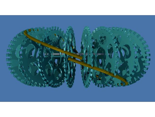
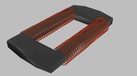
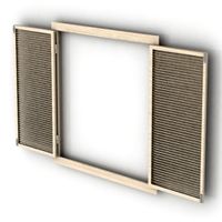
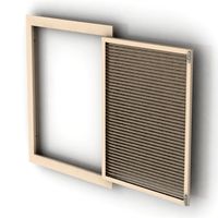
This design caters for the winding wire angle changes as it raps around the frame, eliminating wire bending.
It is a 400mm or 16" outside diameter ABHA Rodin coil frame and have 3rd order Phi proportions using Tom Barnett research to find the proportions. Here is his video https://youtu.be/kxuU8jYkA1k.
I provided the files for a 250mm, 10" coil frame too, in case you do not want to build a large one.
This is not designed for the Daniel Nunez type coil which has the cross winding and he calls it the POE Coil.
On the Tom Barnett video the smallest inner toroid I call the 1st order coil and the one bigger is the 3rd order since it has the Do=outside coil diameter and the Di=inside coil diameter in the proportions Do:Di=Phi^3 and as such it has the pattern of 36x36 according to Tom Barnett's suggestion. Just as a reminder, Phi is the a constant called the Golden Ratio which is Phi=1.618. See how calculations are done for the different order coils in the image above or in the PDF provided in the 'Things Files' section.
I updated the PDF document and now has some sample calculations to show how to design different dimension and order Phi proportion Rodin coils.
The various patterns come from and can be found here https://youtu.be/7pvuTZ5u6Kg which is the YouTube channel of Randy Powell, the discoverer of this modeling.
You can scale this design, of course, but I would not go smaller than Do=200mm or 8", otherwise the ribs/formers get too thin and flimsy.
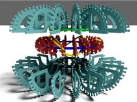
See images how the winding is going around the coil. The images show one loop only so you can see the path clearly. The colour markings help to see that every 2nd grove has the wire bundle routed through it, on the adjacent former.
This design has 16 ribs or former to try to get as close to the correct wire path as possible. This also makes it simpler as the former are symmetrical all around the ring. Make sure that the tabs on the former are all facing the same way as the slot is not in the center, due to the cable routing, see video here => https://youtu.be/ohHqAKv_6No
I provided the files for a smaller Do=250mm too which is reflected in the file names. Just in case you do not want to build the larger one.
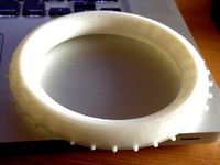
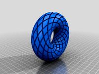
The green coil frame which is built on the photos is the 250mm diameter one. It can take about 1kg of wire. This one has a bifilar 0.63mm diameter winding wire and they create 2 coils with 8.5 Ohm resistance each. The bifilar winding wire is just goes around as long as it runs out so it only has 2 x 2 connections. It took a few hours to wind it on the coil as it went around it about 6 times.
I included the 36:36 pattern image which will allow you to build and experiment with different map configurations and sizes while modelling the different order coil vortexes. It can be the bases of other patterns with duplication and overlaying.
Just click on the X to enlarge the image and then a link will appear 'View Original'. Click on it and when the image appears right click on it and save the image to your computer.
3D Printing:
I print straight to the print bed without any foundation or support. For this you need to make sure that your printer sensor is calibrated correctly. I use 5 point print bed calibration. These parts fit on a 200mm x 200mm print bed.
It is a 400mm or 16" outside diameter ABHA Rodin coil frame and have 3rd order Phi proportions using Tom Barnett research to find the proportions. Here is his video https://youtu.be/kxuU8jYkA1k.
I provided the files for a 250mm, 10" coil frame too, in case you do not want to build a large one.
This is not designed for the Daniel Nunez type coil which has the cross winding and he calls it the POE Coil.
On the Tom Barnett video the smallest inner toroid I call the 1st order coil and the one bigger is the 3rd order since it has the Do=outside coil diameter and the Di=inside coil diameter in the proportions Do:Di=Phi^3 and as such it has the pattern of 36x36 according to Tom Barnett's suggestion. Just as a reminder, Phi is the a constant called the Golden Ratio which is Phi=1.618. See how calculations are done for the different order coils in the image above or in the PDF provided in the 'Things Files' section.
I updated the PDF document and now has some sample calculations to show how to design different dimension and order Phi proportion Rodin coils.
The various patterns come from and can be found here https://youtu.be/7pvuTZ5u6Kg which is the YouTube channel of Randy Powell, the discoverer of this modeling.
You can scale this design, of course, but I would not go smaller than Do=200mm or 8", otherwise the ribs/formers get too thin and flimsy.
See images how the winding is going around the coil. The images show one loop only so you can see the path clearly. The colour markings help to see that every 2nd grove has the wire bundle routed through it, on the adjacent former.
This design has 16 ribs or former to try to get as close to the correct wire path as possible. This also makes it simpler as the former are symmetrical all around the ring. Make sure that the tabs on the former are all facing the same way as the slot is not in the center, due to the cable routing, see video here => https://youtu.be/ohHqAKv_6No
I provided the files for a smaller Do=250mm too which is reflected in the file names. Just in case you do not want to build the larger one.
The green coil frame which is built on the photos is the 250mm diameter one. It can take about 1kg of wire. This one has a bifilar 0.63mm diameter winding wire and they create 2 coils with 8.5 Ohm resistance each. The bifilar winding wire is just goes around as long as it runs out so it only has 2 x 2 connections. It took a few hours to wind it on the coil as it went around it about 6 times.
I included the 36:36 pattern image which will allow you to build and experiment with different map configurations and sizes while modelling the different order coil vortexes. It can be the bases of other patterns with duplication and overlaying.
Just click on the X to enlarge the image and then a link will appear 'View Original'. Click on it and when the image appears right click on it and save the image to your computer.
3D Printing:
I print straight to the print bed without any foundation or support. For this you need to make sure that your printer sensor is calibrated correctly. I use 5 point print bed calibration. These parts fit on a 200mm x 200mm print bed.
Similar models
thingiverse
free
Nested ABHA Rodin Coil Frames - 1st & 3rd Order by spard001
...ill appear 'view original'. click on it and when the image appears right click on it and save the image to your computer.
thingiverse
free

POE Vortex Coil (Rodin Coil) by Iskender
... (rodin coil) by iskender
thingiverse
its a frame for rodin coil, it has 12 discs around with 12 inlets for wire to wind around.
grabcad
free

Rodin Coil
...rodin coil
grabcad
abha
grabcad
free

POE Vortex Coil
...e discs should be thicker. discs edges was inspired by kyrgyz nomadic carpets patterns which gives functionality to wind 2 coils.
thingiverse
free

Rodin coil donut creator by Bobnet
...rodin coil donut creator by bobnet
thingiverse
the rodin coil consists of a pair of wires wrapped around a doughnut-shaped core.
thingiverse
free

Rodin Coil Frame by Syncro
...ill like please feel free to share.
i have started making other designs for testing and may upload them if there is any interest.
thingiverse
free

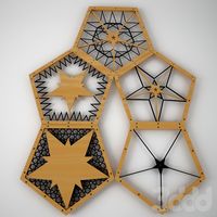
Rodin Star coil winding jig 12 point by jerid
...rodin star coil winding jig 12 point by jerid
thingiverse
jig for winding a 12 point rodin starship coil
thingiverse
free

Rodin Coil Formers (12 / 36 Point) by relic
...ertain freqs - could have a positive effect. imho, i believe that this therapy could be as simple as described.
happy winding !!!
thingiverse
free
Rodin Coil Jig by jerid
...rodin coil jig by jerid
thingiverse
torus with notches for winding a rodin coil.
print 2 then glue together.
grabcad
free

Rodin Coil Winder Revision 1
...cad
this was modelled by will green, and it is at this point incomplete. it is designed to automate the windings of rodin coils.
Spard001
thingiverse
free
Adjustable Tubular Arrow Quiver Stand by spard001
...e side of the tube.
the smaller part of the hook is for the tube and the longer is for the lid to make the cap stand up straight.
thingiverse
free
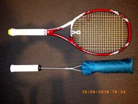
Tennis Serve Trainer Aid by spard001
...this guy's explanation how to use it https://www.youtube.com/watch?v=ovh7tsa2r6i
the grip size of this design is 4 3/8 or g3.
thingiverse
free
Helix RH clamp for BPE Pro arrow fletching jig (may suit other jigs as well) by spard001
...n the arrow slowly tighten the nobs and readjust if necessary and tighten it further until it is completely locked into position.
thingiverse
free

Spot Hogg Fast Eddie XL compound bow sight - single pin scope triple alignment ring by spard001
...omes with the sight are for yards and for us who use meters it does not help much. with these you can do your own meter sight in.
thingiverse
free
Nested ABHA Rodin Coil Frames - 1st & 3rd Order by spard001
...ill appear 'view original'. click on it and when the image appears right click on it and save the image to your computer.
Abha
thingiverse
free

ABHA coil support - Two pieces by StefanDanov
...oil with double overlying path for a perfect geometric shape.
many thanks to mr giancarlo ariazzi and his team for this design!
thingiverse
free
ABHA coil support - One piece by StefanDanov
...oil with double overlying path for a perfect geometric shape.
many thanks to mr giancarlo ariazzi and his team for this design!
thingiverse
free

ABHA Torus 18x36 Nested Vorticies by Vortex87
...s, sunflowers, the path of least resistance. this will be a difficult challenge for any 3d printer, if anyone can,, send me a pm.
blendswap
free

Parametric ABHA Torus
...tbln films, to premier december 25th 2013.http://www.randysdonutsmovie.com/latest change on 2013/12/23, 19:05:36added video demo.
thingiverse
free

ABHA Mini by Bloon
....com/watch?v=0wvdzsqhohk
enjoy, like, share and spread the word
please make it and share it and let's change the world :)
thingiverse
free

ABHA Torus 18X36 Printable by Vortex87
...n the extreme overhangs, so i created two halves. this way there will be no overhangs, special thanks to chris cecil for the tip!
thingiverse
free

36 x 36 ABHA Coil Bobbin by firepinto
... of the torus as on the outer parts.
https://www.youtube.com/watch?v=xdlkqtqjmxc
https://www.youtube.com/watch?v=r19agtppcko
thingiverse
free

ABHA Torus Pulse Motor by firepinto
...had tried to use a bedini circuit, but had no luck. you can see my final result here: http://www.youtube.com/watch?v=8z7jodtxlz4
thingiverse
free

Egg Donut by espen
...13 pieced egg donut attemt of replicating daniel nunez`s abha ...
thingiverse
free

Baha'i Prayer Ring by msprout
...baha'i prayer ring by msprout thingiverse allah-u-abha do your 95 in style with this baha'i prayer...
Rodin
turbosquid
$10

Rodin's Thinker
...el rodin's thinker for download as c4d, fbx, obj, and 3ds on turbosquid: 3d models for games, architecture, videos. (1690114)
turbosquid
$15

Auguste Rodin Eva Eve
...model auguste rodin eva eve for download as max, obj, and fbx on turbosquid: 3d models for games, architecture, videos. (1496129)
turbosquid
$25

Auguste Rodin - St. John The Baptist Preaching
...te rodin - st. john the baptist preaching for download as max on turbosquid: 3d models for games, architecture, videos. (1150179)
3ddd
$1
Без названия
...без названия 3ddd poltroncina , rodin rodin lounge...
3ddd
free

Огюст Роден Рука Бога
...(мрамор) the hand of god, 1898 (marble) , artist: rodin auguste...
3d_export
$169

David Statue 3D Model 3D Model
...3dexport david statue michelangelo sculpture sculpt donatello bernini auguste rodin the thinker mermaid masterpiece renaissance florence marble palazzo della...
3d_sky
free

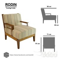
Rodin Lounge chair
...rodin lounge chair
3dsky
rodin lounge chair
sketchfab
$40

Rodin Museum Musee Rodin Paris France
...0 visitors annually.
modeling in blender - rodin museum musee rodin paris france - buy royalty free 3d model by cuankiproduction
unity_asset_store
$5

Rodin's Statues
...low with the rodin's statues asset from the new way museum. find this & other props options on the unity asset store.
3d_sky
free

Auguste Rodin The Hand Of God
...y
hand marble sculpture
auguste rodin the hand of god (marble)
the hand of god, 1898 (marble), artist: rodin, auguste (1840-1917)
Phi
3d_ocean
$25
MW3DHDR0029 Phi Phi Island Beach Thailand
...g without all the people and some long tail boats in the water. super hight resolution hdri with tonemapped background and sib...
3ddd
free

Carpet PHI by Artisan
...
карты bump (при близких увеличивать значение тайлинга, при дальних уменьшать )
вес геометрии ковра - 25 мб
размеры: d 2250мм
3d_export
$37

PH production 3D Model
...3dexport model3d 3d cinema4d c4d cinema4d robot war by phi ...
thingiverse
free

Phi by mumford237
...phi by mumford237
thingiverse
greek letter phi
thingiverse
free

Phi by Rhull
...phi by rhull
thingiverse
phi symbol - made in google sketchup
thingiverse
free

Phi tieu by Phong
...phi tieu by phong
thingiverse
phi tieu
thingiverse
free

Minion Phi by Friedzombie
...minion phi by friedzombie
thingiverse
minion phi suitable for a lasercutter
thingiverse
free

Letter phi by Armand_81
...letter phi by armand_81
thingiverse
le symbole phi de la france insoumise
artstation
$2

Phi Scissor by Hay
...phi scissor by hay
artstation
thingiverse
free

Gamma Phi Beta Logo
...gamma phi beta logo
thingiverse
gamma phi beta logo designed in solidworks
36X36
thingiverse
free

FrSky XSR Mount 36x36 by luivri
...frsky xsr mount 36x36 by luivri
thingiverse
.
sketchfab
$7

Stylex Cove Table Soft 36x36
...gh texel density. element ids for easy shader customization - stylex cove table soft 36x36 - buy royalty free 3d model by tmrwinc
thingiverse
free

Frsky XM+ POD 36x36 by Lillorillo
...frsky xm+ pod 36x36 by lillorillo
thingiverse
remouve antenna glue and place orizzontal
thingiverse
free

ZOHD Drift 36x36 FC holder by SLOWY
...in the lower equipment bay with this fc mount.
i used the matek f405-ctr.
you need two of these and 4x m3 nilon nuts for mounting
thingiverse
free

Basic 36x36 Box
...oard with 30.5mm hope spacing like flight controllers and such.
m3 screws of appropriate length (i used 6mm) to hold it together.
thingiverse
free

vtx reciever stack 36x36 by jr555se
...re bind button and cutouts for zipties prepared :) it's 1mm thick to reduce weight but also let the nylon absorb the shocks.
thingiverse
free

36x36 dummy plate for mini quadcopters stacks by ericmoritz
...opters stacks by ericmoritz
thingiverse
this is a dummy plate for your stack that lets you foam tape/zip tie receivers and vtxs.
thingiverse
free

OP Revolution 36x36 10mm spacer by ntthhtl
...ngiverse
10mm tall spacer for revo. can be stacked on top of pdb. holes for esc wires etc. hole for 2pos switch (eg. pololu en).
thingiverse
free

FrSky D4R-II Tray (36x36) by kcchen_00
...ethod to keep the rx in place... allows for quick glance at status led.
use zip tie / "rapstrap" to secure otherwise.
thingiverse
free

Graupner GR 18 Hott Matek Micro PDB 36x36 Mount by JOEFX
...mm. fasten the gr-18 and the matek pdb with double -sided tape. the best tape for that will be the foam like for example from 3m.
Coil
3d_export
$5

Tesla coil
...tesla coil
3dexport
detailed tesla coil model
archibase_planet
free

Fan coil
...fan coil unit air conditioning daikin conditioner
fan coil daikin n160915 - 3d model (*.gsm+*.3ds) for exterior 3d visualization.
cg_studio
$20

Coiled Rope3d model
...pe lasso coil bustermk2 coiled cord
.max - coiled rope 3d model, royalty free license available, instant download after purchase.
turbosquid
$8

Tesla Coil
...bosquid
royalty free 3d model tesla coil for download as fbx on turbosquid: 3d models for games, architecture, videos. (1458990)
turbosquid
$29

Mosquito Coil
...oyalty free 3d model mosquito coil for download as ma and obj on turbosquid: 3d models for games, architecture, videos. (1263002)
turbosquid
$2

electronic coil
...y free 3d model electronic coil for download as obj and blend on turbosquid: 3d models for games, architecture, videos. (1503485)
turbosquid
$2
ferrite coil
...alty free 3d model ferrite coil for download as blend and obj on turbosquid: 3d models for games, architecture, videos. (1588248)
turbosquid
$15
Tesla Coil
... available on turbo squid, the world's leading provider of digital 3d models for visualization, films, television, and games.
turbosquid
$10

coil gun
... available on turbo squid, the world's leading provider of digital 3d models for visualization, films, television, and games.
turbosquid
$4

The transition coil
... available on turbo squid, the world's leading provider of digital 3d models for visualization, films, television, and games.
Proportions
3ddd
$1
PROPORTION II
...proportion ii
3ddd
malabar emotional
консоль proportion ii
malabar emotional design
коллекция euphoria
turbosquid
$35

Proportional Divider
...l proportional divider for download as 3ds, obj, 3dm, and skp on turbosquid: 3d models for games, architecture, videos. (1304518)
3ddd
$1
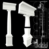
tuscan column with exact proportions
...tions from vignola book, with cad file and 3d model , you can use it in your scene , or in your book to explain the proportions ,
turbosquid
$4

Female Base Mesh with Anime Proportions
...th anime proportions for download as blend, fbx, dae, and obj on turbosquid: 3d models for games, architecture, videos. (1670928)
3d_export
$19

realistic female legs natural proportions base mesh
...t is provided for the compatibility with cad-oriented 3d software and its resolution may be insufficient for quality 3d printing.
3ddd
$1

tuscan temple
...is the tuscan temple and again it the exact proportions it is very useful for architects who is studding...
3d_export
$15

Stationwagon
...stationwagon
3dexport
volvo cross country concept model proportion : [1:5]
3d_export
$5

collection of lego bricks
...are 61 lego pieces of the same scale and proportions ...
3d_export
$5

pendulum of newton
...newton 3dexport newton's pendulum is made with respect to proportions and...
3d_export
$5

Black cello
...black cello 3dexport low-poly instrument. proportions are accurate, no f-holes, no...
Pattern
3d_export
$10

pattern
...pattern
3dexport
old carved pattern
3d_ocean
$4

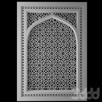
Window Pattern
...c4d cinema4d design element geometry geometry pattern grill pattern pattern vray vrayforc4d window pattern
window or wall pattern
design_connected
$18

Pattern
...pattern
designconnected
emu group pattern computer generated 3d model. designed by levy, arik.
3ddd
$1
pattern
...pattern
3ddd
решетка
1000x1000
3ddd
$1

Stucco pattern
...stucco pattern
3ddd
розетка
stucco pattern
3d_ocean
$10
Pattern
...pattern
3docean
extrude
national ornament
turbosquid
$6

Pattern
... available on turbo squid, the world's leading provider of digital 3d models for visualization, films, television, and games.
turbosquid
$25

Wall Pattern A05 (pattern only)
... available on turbo squid, the world's leading provider of digital 3d models for visualization, films, television, and games.
turbosquid
$25
Wall Pattern A04 (pattern only)
... available on turbo squid, the world's leading provider of digital 3d models for visualization, films, television, and games.
turbosquid
$25
Wall Pattern A03 (pattern only)
... available on turbo squid, the world's leading provider of digital 3d models for visualization, films, television, and games.
Frame
archibase_planet
free
Frame
...frame
archibase planet
frame photo frame
frame n190813 - 3d model (*.gsm+*.3ds) for interior 3d visualization.
archibase_planet
free

Frame
...frame
archibase planet
frame photo frame
frame n071113 - 3d model (*.gsm+*.3ds) for interior 3d visualization.
3ddd
$1

Frame
...frame
3ddd
frame
3ddd
free
Frame
...frame
3ddd
frame
archibase_planet
free

Frame
...frame
archibase planet
frame mirror frame ornament
frame n260113 - 3d model (*.gsm+*.3ds) for interior 3d visualization.
archibase_planet
free

Frame
...frame
archibase planet
frame photo frame
frame photo n190813 - 3d model (*.gsm+*.3ds) for interior 3d visualization.
archibase_planet
free
Frame
...frame
archibase planet
frame window window frame
frame 1 - 3d model (*.gsm+*.3ds) for interior 3d visualization.
archibase_planet
free
Frame
...frame
archibase planet
frame window frame window
frame 3 - 3d model (*.gsm+*.3ds) for interior 3d visualization.
archibase_planet
free
Frame
...frame
archibase planet
frame wall frame decoration
frame 1 - 3d model (*.gsm+*.3ds) for interior 3d visualization.
archibase_planet
free
Frame
...frame
archibase planet
frame window window frame
frame 2 - 3d model (*.gsm+*.3ds) for interior 3d visualization.