Thingiverse
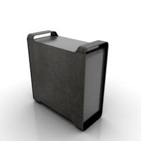
A300 thin case
by Thingiverse
Last crawled date: 4 years, 3 months ago
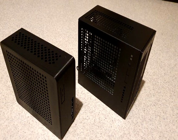
Thin case for ASRock A300 motherboard.
Dimensions for case are 150,9mm x 143,5mm x 54,4mm(not counting height of screws or taped pads if used).
Case is meant for use with Noctua NH-L9a-AM4(or Intel variant, Intel motherboard compatibility not checked) cooler and M.2 drive(s) (bottom M.2 has no ventilation). No room for SSD drives.
Different top models for different lenght M3 spacer nuts.
No stress testing done, so depending of material, might heat warp in heavy use.
Print in pictures done with Middle_with_supports.stl and Top_6mm.stl, bottom.stl made 0,5mm thicker after printing for rigidity, but not test printed after model change.
Things needed:
ASRock DeskMini A300 -> motherboard and power button+power button screw
Noctua NH-L9a-AM4 cooler or cooler with shorter height.
4 x M3 20mm screws.
4 x M3 female/female hex spacer nuts(hex size for the ones I used was 4,6mm)
4 x M3 washers, if not using countersunk ones.
Sharp knife to cut power button supports.
Print/STL notes:
TOP
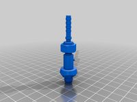
M3 hex spacers inserted in each leg, pausing print, before leg ends are capped. Each model from 4 to 12 have 0,5mm extra lenght (6mm has 6,5mm etc.), with layer height of 0,2mm there's 2 layers cap before end is sealed. If pausing print manually, instead of gcode, those 2 layers go by fast, so be ready.
If no female/female hex spacers available, motherboard standoff should also work, if correct lenght and paired with screw with same thread.
MIDDLE
3 different versions of STL provided.
Middle_with_supports.stl file has custom support stuctures for both IO ports and power button. Uses more material, but IO port supports touch only top side of ports and there should be minimal cleanup if at all.
Middle_PW_button_support_only.stl file, as named, only build in supports for power button.
Middle_no_supports.stl file, no in build supports.
BOTTOM
2 different files, one for countersink screws and other non countersunk one.
Assembly notes:
After printing middle parts remove supports and cut power button free.
From bottom up, components should go as followed. Bottom, motherboard, middle and top.
Old screw that holds power button in original case used to attach power button. Easiest to attach to middle part before assembly.
Notes:
Motherboard is tight fit in middle.stl, mine was lopsided before tightening top and bottom with it and it straightened with very little force. Scale if too tight.
Models with different supports for middle part. I printed mine with custom supports one, as I haven't had much success with Curas supports.
Supports for power button can be only cut to free it, no need to remove them completely, as it has only ~1mm travel distance.
Legs in top part of the case have M3 female/female hex spacer nuts inserted mid print in each leg, for assembly.
Cooler height under 38mm needed, Noctua NH-L9a-AM4 height is 37mm and has ~1mm clearance.
Bottom M.2 slot not tested, bottom slot might have heat issues, as it has no ventilation.
IO ports in middle-model moved a little and columns in between front IO removed(those broke off easily), after I printed my case, should be better fit, but not tested.
Bottom_countersink.stl countersink size not tested.
Dimensions for case are 150,9mm x 143,5mm x 54,4mm(not counting height of screws or taped pads if used).
Case is meant for use with Noctua NH-L9a-AM4(or Intel variant, Intel motherboard compatibility not checked) cooler and M.2 drive(s) (bottom M.2 has no ventilation). No room for SSD drives.
Different top models for different lenght M3 spacer nuts.
No stress testing done, so depending of material, might heat warp in heavy use.
Print in pictures done with Middle_with_supports.stl and Top_6mm.stl, bottom.stl made 0,5mm thicker after printing for rigidity, but not test printed after model change.
Things needed:
ASRock DeskMini A300 -> motherboard and power button+power button screw
Noctua NH-L9a-AM4 cooler or cooler with shorter height.
4 x M3 20mm screws.
4 x M3 female/female hex spacer nuts(hex size for the ones I used was 4,6mm)
4 x M3 washers, if not using countersunk ones.
Sharp knife to cut power button supports.
Print/STL notes:
TOP
M3 hex spacers inserted in each leg, pausing print, before leg ends are capped. Each model from 4 to 12 have 0,5mm extra lenght (6mm has 6,5mm etc.), with layer height of 0,2mm there's 2 layers cap before end is sealed. If pausing print manually, instead of gcode, those 2 layers go by fast, so be ready.
If no female/female hex spacers available, motherboard standoff should also work, if correct lenght and paired with screw with same thread.
MIDDLE
3 different versions of STL provided.
Middle_with_supports.stl file has custom support stuctures for both IO ports and power button. Uses more material, but IO port supports touch only top side of ports and there should be minimal cleanup if at all.
Middle_PW_button_support_only.stl file, as named, only build in supports for power button.
Middle_no_supports.stl file, no in build supports.
BOTTOM
2 different files, one for countersink screws and other non countersunk one.
Assembly notes:
After printing middle parts remove supports and cut power button free.
From bottom up, components should go as followed. Bottom, motherboard, middle and top.
Old screw that holds power button in original case used to attach power button. Easiest to attach to middle part before assembly.
Notes:
Motherboard is tight fit in middle.stl, mine was lopsided before tightening top and bottom with it and it straightened with very little force. Scale if too tight.
Models with different supports for middle part. I printed mine with custom supports one, as I haven't had much success with Curas supports.
Supports for power button can be only cut to free it, no need to remove them completely, as it has only ~1mm travel distance.
Legs in top part of the case have M3 female/female hex spacer nuts inserted mid print in each leg, for assembly.
Cooler height under 38mm needed, Noctua NH-L9a-AM4 height is 37mm and has ~1mm clearance.
Bottom M.2 slot not tested, bottom slot might have heat issues, as it has no ventilation.
IO ports in middle-model moved a little and columns in between front IO removed(those broke off easily), after I printed my case, should be better fit, but not tested.
Bottom_countersink.stl countersink size not tested.
Similar models
3dwarehouse
free

Noctua NH-L12S
... 70mm instead of 66mm height. heatpipes redone. heatsink is 25mm instead of 23mm from noctua l12. 120mm bottom fan mount support.
grabcad
free

Hex Spacers M3 Female-Female
...hex spacers m3 female-female
grabcad
hex spacers m3 female-female with length from 5mm to 60mm for printed circuit boards.
grabcad
free

NOCTUA NH-D9L NH-D9X CPU Cooler
...h-d14-cpu-cooler-1
https://grabcad.com/library/noctua-nh-d15-cpu-cooler-1
https://grabcad.com/library/noctua-nh-d15s-cpu-cooler-1
grabcad
free

NOCTUA NH-D15S CPU Cooler
...-l9x65-cpu-cooler-1
https://grabcad.com/library/noctua-nh-d14-cpu-cooler-1
https://grabcad.com/library/noctua-nh-d15-cpu-cooler-1
grabcad
free

NOCTUA NH-D15 CPU Cooler
...l9x65-cpu-cooler-1
https://grabcad.com/library/noctua-nh-d14-cpu-cooler-1
https://grabcad.com/library/noctua-nh-d15s-cpu-cooler-1
grabcad
free

Hex Spacers M3 Male-Female
...hex spacers m3 male-female
grabcad
hex spacers m3 male-female with length from 5mm to 60mm for printed circuit boards.
grabcad
free

Noctua NH-L9X65
...noctua nh-l9x65
grabcad
cooler noctua nh-l9x65
thingiverse
free
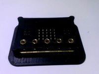
BBC microbit case by dbrockbank
...al spacer m3 7+4mm to fix micro:bit to the bottom part of the case. use the brass standoffs to attach crocodile clip test leads.
grabcad
free

M3 x10mm spacer
...m3 x10mm spacer
grabcad
m3*6l+10mm standoff spacer female male spacing screws threaded spacer hex spacer
grabcad
free

Noctua NH-L9i
...noctua nh-l9i
grabcad
cooler 37mm noctua nh-l9i
A300
cg_studio
$100
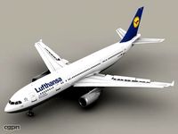
Airbus A300 Lufthansa3d model
...model
cgstudio
.3ds .max .obj - airbus a300 lufthansa 3d model, royalty free license available, instant download after purchase.
3d_export
$100
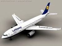
Airbus A300 Lufthansa 3D Model
...ansa plane planes airplane airplanes aircraft aircrafts airliner airliners
airbus a300 lufthansa 3d model behr bros 3554 3dexport
3d_export
$35
Mars - a300 spaceship
... stl extensions x-ray tests are clean. model polygons are triangles.models are low polygon. my own design style is also products.
cg_studio
$60
Airbus A3003d model
...ger industries jet civilian widebody
.mb - airbus a300 3d model, royalty free license available, instant download after purchase.
3d_export
$120

Airbus A330200 Air France 3D Model
...france 300 jet airline airways aircraft air plane commercial a300 airbus a330200 air france 3d model tartino 36083...
cg_studio
$130
Airbus A330-200 Air France3d model
...a330-200 air france 300 jet airline airways plane commercial a300 .3ds .c4d .dxf .obj - airbus a330-200 air france...
3dfindit
free

A300
...a300
3dfind.it
catalog: abb low voltage & systems
thingiverse
free
Airbus A300-600 by P6619
...airbus a300-600 by p6619
thingiverse
this is a airbus a300-600
thingiverse
free
A300 Bit
...e. this is a full piece, you will have to slice it in half to stick to your blaster. it is an exact copy of a screen used part.
thingiverse
free

ASRock A300 mainboard
...ingiverse
asrock a300 mainboard
measurement accuracy ~ 0,5mm
2 files, one only mainboard, and second - mainboard with components
Thin
3d_export
$5

Thin man
...thin man
3dexport
thin man with no eyes<br>.blend,
design_connected
$13
Thin-K
...thin-k
designconnected
kristalia thin-k computer generated 3d model. designed by bertoncini, luciano.
3d_export
$5

thin door knob
...thin door knob
3dexport
thin door knob
3d_ocean
$18
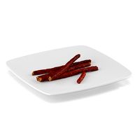
Thin sausage
... snack thin vray wooden
3d model of four thin sausages and one small. 3d scanned from real product. placed on white square plate.
turbosquid
$100

Cartoon thin
... available on turbo squid, the world's leading provider of digital 3d models for visualization, films, television, and games.
turbosquid
$99

Thin Boy
... available on turbo squid, the world's leading provider of digital 3d models for visualization, films, television, and games.
turbosquid
$35
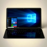
Thin Laptop
... model thin laptop for download as ma, c4d, max, fbx, and obj on turbosquid: 3d models for games, architecture, videos. (1710537)
turbosquid
$15

Thin Wheel
... available on turbo squid, the world's leading provider of digital 3d models for visualization, films, television, and games.
3ddd
$1
Thin фабрики Bonaldo
...thin фабрики bonaldo
3ddd
bonaldo
кровать thin итальянской фабрики bonaldo,постельное белье. polys-119097
3d_export
$20

Thin Tree 3D Model
...thin tree 3d model
3dexport
thin tree hi res
thin tree 3d model ifrost 7036 3dexport
Case
3d_export
$1
case
...case
3dexport
case
archibase_planet
free
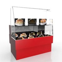
Case
...case
archibase planet
showcase show-case glass case
glass-case + cakes - 3d model for interior 3d visualization.
archibase_planet
free
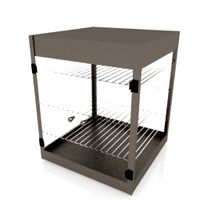
Case
...case
archibase planet
showcase show-case glass case
glass-case for chips - 3d model for interior 3d visualization.
archibase_planet
free
Case
...case
archibase planet
case shelving drawer
case - 3d model for interior 3d visualization.
archibase_planet
free
Case
...case
archibase planet
case rack locker
case - 3d model for interior 3d visualization.
archibase_planet
free
Case
...case
archibase planet
case drawer kitchen furniture
case - 3d model for interior 3d visualization.
archibase_planet
free
Case
...case
archibase planet
case cupboard shelving
glass case - 3d model for interior 3d visualization.
archibase_planet
free
Case
...case
archibase planet
case handbag suitcase
case - 3d model (*.gsm+*.3ds) for interior 3d visualization.
archibase_planet
free
Case
...case
archibase planet
case suitcase
case 5 - 3d model (*.gsm+*.3ds) for interior 3d visualization.
archibase_planet
free
Case
...case
archibase planet
locker case dresser
case - 3d model (*.gsm+*.3ds) for interior 3d visualization.