Thingiverse

Trigorilla pro schematics and reverse engineering by gerryc89
by Thingiverse
Last crawled date: 4 years ago
Anycubic Trigorilla pro specs and mcu pinout
32bit Cortex-M3 MCU (STM32F103ZET6) 8MHz crystal
Soldered 5x A4988 stepper drivers configured to 16 microsteps (MS all to 3v3)
WIFI slot for ESP-01S
Onboard Winbond W25Q16JV 16Mbit SPI Flash
Onboard 24C16 I2C 16Kbit EEPROM
1F SuperCapacitor for blackout data backup with a mosfet for pwm charge
Onboard SD Card slot and pin header
USB Serial communication
Buzzer, sw controlled internal led
Second Extruder-Hotend DaughterBoard predisposition
Mounted in Anycubic Predator, I3 Mega and ecc with 4 inch Touch LCD
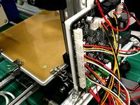
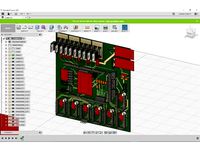
I have recostructed the schematics of this board from my predator, i hope that
in some time is possible to implement a custom firmware for this board without
change it. The schematics is designed with eagle cad free and is for only for
study purpose, only the foundamental signals are drawed, and some components
that i have selected are incorrect for the pcb, but for the digital wiring sense
is ok. The library for the drawing are all included, created from the
respectively authors.
Jumpers
JP1 = Bootloader, remove and power up for flashing
SW1 = 5V From usb or internal psu, is used for flash w/out psu
Stepper controllers and cpu pin cross table
X-MOTOR
DIR = PE6
STEP = PE5
nENABLE = PC13
Y-MOTOR
DIR = PE3
STEP = PE2
nENABLE = PE4
Z-MOTOR
DIR = PE0
STEP = PB8
nENABLE = PE1
EXTRUDER-MOTOR
DIR = PB5
STEP = PB4
nENABLE = PB9
Z2-MOTOR (not used in predator)
DIR = PC6
STEP = PC7
nENABLE = PG8
Digital Sensors all pull-upped to 5v
FILAMENT1 = PA15
Z- = PA14
Z+ = PA13 (autolevel removable switch un predator)
Y- = PA12
X- = PG10
Analog Sensors all pull-upped to 3v3
E-TEMP = PA1
B-TEMP = PA0
Fans
M-FAN = PD6 (internal motherboard for predator)
FAN0 = PG13 (duct blowers for predator)
FAN1 = PG14 (hotend fan for predator)
Heaters
HOT-END1 = PG12
HOTBED = PG11 (inverted)
Second Extruder-Hotend Headers (no signal conditioning, direct connected to cpu)
JP3
1-EXT = PC5 (Extruder STEP?)
2-RVO = PB1 (Extruder DIR?)
3-HOT2 = PG7 (HotEnd control out?)
4-COOL2 = PG6 (HotEnd fan control out?)
5-TEMP2 = PA2 (HotEnd ADC sensor in?)
JP6
1-GND
2-12/24V
3-12/24V
4-GND
5-GND
6-3V3
7-FILAMENT2 = PA3 (Second filament runout sensor?)
Voltage Alarm, SuperCapacitor and signaling
ALARM = PG2 (12/24V monitoring comparator output, to trigger backup)
PWM-OUT = PG4 (PWM generated from CPU for charge supercap w/out damange)
BUZZER = PB0 (frequency generated from cpu)
LED = PD3 (internal led inverted logic)
Memory
24C16
SCL = PG0
SDA = PG1
W25W16JV
nCS = PB12
CLK = PB13
DO = PB14
DI = PB15
SD Card slot and pin header JP2 (all pull-upped to 3v3 except CK)
CMD = PD2
CK PC12
D0 PC8
D1 PC9
D2 PC10
D3 PC11
Wi-Fi ESP01S ESP8266 Module socket J1
1 RX = PB10
2 3V3
3 GND
4 GPIO = PD12 (reset?)
5 NC
6 3V3
7 GND
8 TX PB11
orientation
|1|2| CPU
|3|4|
|5|6|
|7|8|
USB Serial communication
TX = PA9 (to RX pin of the PL2303)
RX = PA10 (to TX pin of the PL2303)
LCD Touch Display connector 39 pin start from X- connector
1 = 3V3
2 = NC
3 = NC
4 = NC
5 = GND
6 = PD14
7 = PD15
8 = PD0
9 = PD1
10 = PD7
11 = PD11
12 = PD5
13 = PD4
14 = PD13
15 = PE7
16 = PE11
17 = PE12
18 = PE13
19 = PE14
20 = PE15
21 = PD8
22 = PD9
23 = PD10
24 = PB6
25 = PA6
26 = PB7
27 = PA5
28 = PF11
29 = PE8
30 = PE9
31 = PE10
32 = GND
33 = GND
34 = GND
35 = 5V
36 = 5V
37 = 3V3
38 = 3V3
39 = 3V3
32bit Cortex-M3 MCU (STM32F103ZET6) 8MHz crystal
Soldered 5x A4988 stepper drivers configured to 16 microsteps (MS all to 3v3)
WIFI slot for ESP-01S
Onboard Winbond W25Q16JV 16Mbit SPI Flash
Onboard 24C16 I2C 16Kbit EEPROM
1F SuperCapacitor for blackout data backup with a mosfet for pwm charge
Onboard SD Card slot and pin header
USB Serial communication
Buzzer, sw controlled internal led
Second Extruder-Hotend DaughterBoard predisposition
Mounted in Anycubic Predator, I3 Mega and ecc with 4 inch Touch LCD
I have recostructed the schematics of this board from my predator, i hope that
in some time is possible to implement a custom firmware for this board without
change it. The schematics is designed with eagle cad free and is for only for
study purpose, only the foundamental signals are drawed, and some components
that i have selected are incorrect for the pcb, but for the digital wiring sense
is ok. The library for the drawing are all included, created from the
respectively authors.
Jumpers
JP1 = Bootloader, remove and power up for flashing
SW1 = 5V From usb or internal psu, is used for flash w/out psu
Stepper controllers and cpu pin cross table
X-MOTOR
DIR = PE6
STEP = PE5
nENABLE = PC13
Y-MOTOR
DIR = PE3
STEP = PE2
nENABLE = PE4
Z-MOTOR
DIR = PE0
STEP = PB8
nENABLE = PE1
EXTRUDER-MOTOR
DIR = PB5
STEP = PB4
nENABLE = PB9
Z2-MOTOR (not used in predator)
DIR = PC6
STEP = PC7
nENABLE = PG8
Digital Sensors all pull-upped to 5v
FILAMENT1 = PA15
Z- = PA14
Z+ = PA13 (autolevel removable switch un predator)
Y- = PA12
X- = PG10
Analog Sensors all pull-upped to 3v3
E-TEMP = PA1
B-TEMP = PA0
Fans
M-FAN = PD6 (internal motherboard for predator)
FAN0 = PG13 (duct blowers for predator)
FAN1 = PG14 (hotend fan for predator)
Heaters
HOT-END1 = PG12
HOTBED = PG11 (inverted)
Second Extruder-Hotend Headers (no signal conditioning, direct connected to cpu)
JP3
1-EXT = PC5 (Extruder STEP?)
2-RVO = PB1 (Extruder DIR?)
3-HOT2 = PG7 (HotEnd control out?)
4-COOL2 = PG6 (HotEnd fan control out?)
5-TEMP2 = PA2 (HotEnd ADC sensor in?)
JP6
1-GND
2-12/24V
3-12/24V
4-GND
5-GND
6-3V3
7-FILAMENT2 = PA3 (Second filament runout sensor?)
Voltage Alarm, SuperCapacitor and signaling
ALARM = PG2 (12/24V monitoring comparator output, to trigger backup)
PWM-OUT = PG4 (PWM generated from CPU for charge supercap w/out damange)
BUZZER = PB0 (frequency generated from cpu)
LED = PD3 (internal led inverted logic)
Memory
24C16
SCL = PG0
SDA = PG1
W25W16JV
nCS = PB12
CLK = PB13
DO = PB14
DI = PB15
SD Card slot and pin header JP2 (all pull-upped to 3v3 except CK)
CMD = PD2
CK PC12
D0 PC8
D1 PC9
D2 PC10
D3 PC11
Wi-Fi ESP01S ESP8266 Module socket J1
1 RX = PB10
2 3V3
3 GND
4 GPIO = PD12 (reset?)
5 NC
6 3V3
7 GND
8 TX PB11
orientation
|1|2| CPU
|3|4|
|5|6|
|7|8|
USB Serial communication
TX = PA9 (to RX pin of the PL2303)
RX = PA10 (to TX pin of the PL2303)
LCD Touch Display connector 39 pin start from X- connector
1 = 3V3
2 = NC
3 = NC
4 = NC
5 = GND
6 = PD14
7 = PD15
8 = PD0
9 = PD1
10 = PD7
11 = PD11
12 = PD5
13 = PD4
14 = PD13
15 = PE7
16 = PE11
17 = PE12
18 = PE13
19 = PE14
20 = PE15
21 = PD8
22 = PD9
23 = PD10
24 = PB6
25 = PA6
26 = PB7
27 = PA5
28 = PF11
29 = PE8
30 = PE9
31 = PE10
32 = GND
33 = GND
34 = GND
35 = 5V
36 = 5V
37 = 3V3
38 = 3V3
39 = 3V3
Similar models
thingiverse
free

Controller case Computer PC 6 Channel 8 Way 4 pin PWM Fan Speed Controller by Dmitry_Nikolaevich
...se
computer pc 6 channel 8 way 4 pin pwm 3 pin fan speed controller pci cover, 12v temperature control for cpu case fan radiator
grabcad
free

4 Pin Fan Header
...4 pin fan header
grabcad
4 pin fan header
thingiverse
free

raspberry pi fan NF-A4X20 5V PWM
...raspberry pi fan nf-a4x20 5v pwm
thingiverse
for a nf-a4x20 5v pwm fan & raspberry pi 3 (or 4)
thingiverse
free
2019 Mac Pro Drive Cage
... of the cable connector, with the tab on top, the pinout is as follows:
(gnd) (12v) (gnd) (5v) (gnd)
(gnd) (12v) (gnd) (5v) (gnd)
thingiverse
free
Velleman K8200 MKS Base Conversion by Middleman
...prap discount smart controller:
edit line 306 to:
define reprap_discount_smart_controller
5) save and upload new firmware changes
3dwarehouse
free
Common Motherboard Components
...1 slot 288 pin ddr4 dimm slot 240 pin ddr3 dimm slot lga 1151 cpu socket lga 1150 cpu socket sata 6gb/s ports capacitors standoff
thingiverse
free

3010 5v Fan Top for Orange Pi PC Case by madmike8
...
i wanted to add a 5v 3010 fan to my orange pi case. so i remixed cyryllo's top. fan connected to gpio pins 4(+5v) and 6(gnd)
thingiverse
free
Shadeling3D Printer Shield by Shadeling
...ilament runout sensor support pin
filament width sensor support pin
z probe sensor support pin
all parts rated for +30v or higher
thingiverse
free

Picoprobe case by OGe
...2x4 female header:
gnd swdio swdclk vsys
gnd rx tx vbus
of course you can decide by yourself which pins to connect to the header.
thingiverse
free
Brushless Motor using CPU FAN hall sensor circuit by Manders36
... brushless fan by harvesting the hall sensor and controller from a 12v cpu fan, hand wound coils, and 4 strong neodymium magnets.
Trigorilla
thingiverse
free

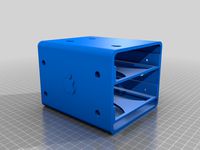
Trigorilla Case by Merlin2105
...trigorilla case by merlin2105
thingiverse
case for trigorilla board
40mm noctua lüftergschutz
thingiverse
free

Case trigorilla for anycubic by MakerDog1
...case trigorilla for anycubic by makerdog1
thingiverse
case trigorilla for anycubic
thingiverse
free

AnyCubic Trigorilla Case by Spacemanballz
...anycubic trigorilla case by spacemanballz
thingiverse
external trigorilla case
m3 nut fit
30mm fan fitting
thingiverse
free

Trigorilla port documentation by an_da_liu
...ocumentation by an_da_liu
thingiverse
additional documentation i made for the trigorilla controll board in the anycubic printer.
thingiverse
free

Trigorilla 2020 Mount by Mka0205
...by mka0205
thingiverse
i was in need of a simple way to mount my trigorilla board to my hypercube 2020 extrusion so i made this.
thingiverse
free
Fan 4010 for drivers trigorilla
...fan 4010 for drivers trigorilla
thingiverse
print vertical
thingiverse
free

TriGorilla board mockup by AlexWaveDiver
...ur cables and case setup without risking a real board.
feel free to comment. criticism is always welcome, as it helps me improve!
thingiverse
free

Anycubic Trigorilla Board Mount by hanser30
...t is specially made for the anycubic linear plus but it could be used in the non plus version and in the pulley version as well.
thingiverse
free

Anycubic Trigorilla Board Template by SirGed
...o an enclosure that mine went into for another build. included a plate as well if you just want to cover the bottom of the board.
thingiverse
free

Trigorilla MOSFET mount for 2020 extrusion by stormtrooperguy
...uy
thingiverse
i made this to mount a trigorilla mosfet on my reworked folgertech i3. should be suitable for any 2020 extrusion.
Schematics
3d_export
$39
Logic Schematic Symbol Collection 3D Model
...or amplifier inverter cob 3ds obj dxf directx visualmotion
logic schematic symbol collection 3d model visualmotion 79452 3dexport
3d_ocean
$17
Schematic city
...oon square cartoon street cartoon town city map road square street town
cartoon low-poly city, a simple model that is easy to use
3d_export
free
set of schematic vessels 3 pieces
..., fbx<br>- count of vertexes : 666000<br>- count of faces:651000<br>https://www.youtube.com/watch?v=nfmnprp0ese
3d_ocean
$10

DNA Model
...dna model
3docean
array dna genes health hi-poly hipoly hospital medicine schematic small
part of dna , schematic
3d_export
$7

Gas burner
...gas burner
3dexport
schematic model of the gas burner weishaupt g30 for boilers heating and hot water supply
3d_export
$10

samsung galaxy s21 ultra 5g
...<br>. this model was precisely created accordingly to the schematics ...
3d_export
$10

samsung galaxy s21 5g
...s21. it has been modeled precisely according to the schematics ...
3d_export
$30
Wind Turbine 3D Model
... alternative electric energy power renewable eco green generator interior schematic
wind turbine 3d model blacks3d 18897 3dexport
3d_export
$26

Oil chart
...olygons (3ds max file): 517 050. quantity of vertex: 585 078. version of the program: 3ds max 2018. type of render: coronarender.
3d_export
$60
Wind Turbine Land 3D Model
...native electric energy power renewable eco green generator interior schematic
wind turbine land 3d model behr bros 11372 3dexport
Reverse
3d_export
$6

auto-reverse
...auto-reverse
3dexport
sofa and chair auto-reverse, coffee table douglas
design_connected
$16

Reverse Chair
...reverse chair
designconnected
moroso reverse chair computer generated 3d model. designed by urquiola, patricia.
design_connected
$29

Auto-Reverse 241
...auto-reverse 241
designconnected
arketipo auto-reverse 241 computer generated 3d model. designed by viganò, giuseppe.
3ddd
$1

Кресло auto-reverse
...erse
фабрика arketipo
кресло auto-reverse
ширина x глубина x высота
1260 x 1030 x 600
плюс материалы для визуализации в короне
design_connected
$29

Auto-Reverse Dream
...ed
photo-realistic 3d models of the auto-reverse dream bed from arketipo for 3d architectural and interior design presentations.
turbosquid
$25

Ring and reverse gems
...yalty free 3d model ring and reverse gems for download as 3dm on turbosquid: 3d models for games, architecture, videos. (1229159)
turbosquid
$10

Reverse Vending Machine
...y free 3d model reverse vending machine for download as sldas on turbosquid: 3d models for games, architecture, videos. (1397437)
turbosquid
$15
reverse blade sword.max
... available on turbo squid, the world's leading provider of digital 3d models for visualization, films, television, and games.
turbosquid
free

Reversed Blade Sword
... available on turbo squid, the world's leading provider of digital 3d models for visualization, films, television, and games.
turbosquid
$150

reverse air filter 7500m3
...id
royalty free 3d model reverse air filter for download as on turbosquid: 3d models for games, architecture, videos. (1410897)
Pro
turbosquid
$29
Pro
...ree 3d model mac pro for download as obj, c4d, fbx, and blend on turbosquid: 3d models for games, architecture, videos. (1505782)
3d_export
$5

iphone 13 pro max and pro
...3 pro max and 13 pro the model is made in four colors (graphite, gold, silver, and blue), all of which are attached in the files.
3d_export
free
sapphire pro
...sapphire pro
3dexport
sapphire pro 3d printer head mask
3d_export
$4

macbook pro
...macbook pro
3dexport
macbook pro 13" inch 2020 years model
3ddd
free
GentleLase Pro
... syneron , candela
gentlelase pro аппарат для лазерной эпиляции
turbosquid
$25

PRO frame
...rbosquid
royalty free 3d model pro frame for download as max on turbosquid: 3d models for games, architecture, videos. (1148329)
turbosquid
$5

Alien pro
...osquid
royalty free 3d model alien pro for download as blend on turbosquid: 3d models for games, architecture, videos. (1678446)
turbosquid
$5

iphone11 pro
...uid
royalty free 3d model iphone11 pro for download as blend on turbosquid: 3d models for games, architecture, videos. (1562707)
3ddd
$1

Mac Pro (appel)
...mac pro (appel)
3ddd
компьютер , apple
mac pro
3ddd
$1
Aviation PRO
... aviation
http://www.oligo.de/en/products/system-luminaires/prod/st-aviation-pro-1.html
Engineering
3d_export
$5
engine
...engine
3dexport
engine
3d_export
free
Engine
...engine
3dexport
engine
archibase_planet
free
Engine
...engine
archibase planet
motor engine
engine - 3d model for interior 3d visualization.
archibase_planet
free
Engine
...engine
archibase planet
motor engine mover
engine n170708 - 3d model (*.3ds) for interior 3d visualization.
archibase_planet
free

Engine
...engine
archibase planet
engine locomotive train
locomotive - 3d model for interior 3d visualization.
turbosquid
$1
ENGINE
...osquid
royalty free 3d model ic engine for download as sldas on turbosquid: 3d models for games, architecture, videos. (1382781)
3d_export
$5

engine
...engine
3dexport
3d_export
free
engine
...engine
3dexport
turbosquid
$1
ENGINE
...y free 3d model engine for download as max, 3ds, stl, and fbx on turbosquid: 3d models for games, architecture, videos. (1673703)
3d_ocean
$16
Auto Engine
...e in inventor and autocad. it is not a complete engine, but contains the main parts of an engine and shows the working principle.