GrabCAD

Sustainapack SDD Rev B
by GrabCAD
Last crawled date: 1 year, 10 months ago
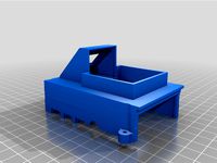
This is basically a revision of my earlier entry “sustainapack entry SDD”. It has been modified to remove material from the injection molded parts tray. This change required the addition of a cardboard box, (see FIG 1) with outside dimensions of 512 x 537 x 389mm, and 2 foam pads. (see FIG 2) This packaging holds 200 low pressure switches. They are arranged in a 5 x 5 (100 sq. mm) matrix and located into pockets formed into an injection molded tray. The trays have been extended on one end by 25 mm and are stacked 8 layers high, rotating alternating flats by 180 degrees. (see FIG 3) The extension and rotation of the flats allows for an interface of the trays making a 43 mm tray height posable. Note the part height is 63.4 high. This is a savings of 20.6mm per layer. The interface also assists in securing the switch inside the package. The parts positioned to the 3 nest pads. (see FIG 4) Located in the bottom of each pocket is pressure pad that works much the same as a snap. It applies pressure to the top of the switches plastic case in the layer below. (see FIG 5) There is no pressure applied to the sheet metal brackets, avoiding damaging. The weight or vertical pressure placed on the container is not applied to the switches. When the box is closed the 6.5mm thick foam sheet are compressed by 2/3 in the contact areas. This will apply constant pressure to the stack. The vertical pressure passes through the box and legs of the trays. The only place the vertical pressure passes though the part is the vertical flanges (variable brackets) on the top layer and passes directly to the tray.
The tray could have more material removed from it and still work. But I think this present design shows the concept. And that further refinement, by me, would only be a guess and a waste of time. I think this tray could easily have mold flow problems and needs mold flow analysis. The same would be true for FEA. I do not know how much force can be exerted if the package would be placed at the bottom of a shipping container? Another item not known is what is the ratio of scrape material generated and material used in the product? I estimate the two plastic parts use 17 cu. cm. of material each. Multiplying this by 25 gives us 425 cu. cm. The (rev B) tray design uses 451.5 cu. cm. of material. This gives a 51.5 % ratio scrape to product. This is probably is not so good. I have seen a 25% regrind used in most drawing that I have done. I assume this is an average lose dew to gates and runners? This would give us a target of 106.25 cu. cm. per tray. Could the regrind material be mixed with filler at 50% to70%? This project offers a big challenge?
The tray could have more material removed from it and still work. But I think this present design shows the concept. And that further refinement, by me, would only be a guess and a waste of time. I think this tray could easily have mold flow problems and needs mold flow analysis. The same would be true for FEA. I do not know how much force can be exerted if the package would be placed at the bottom of a shipping container? Another item not known is what is the ratio of scrape material generated and material used in the product? I estimate the two plastic parts use 17 cu. cm. of material each. Multiplying this by 25 gives us 425 cu. cm. The (rev B) tray design uses 451.5 cu. cm. of material. This gives a 51.5 % ratio scrape to product. This is probably is not so good. I have seen a 25% regrind used in most drawing that I have done. I assume this is an average lose dew to gates and runners? This would give us a target of 106.25 cu. cm. per tray. Could the regrind material be mixed with filler at 50% to70%? This project offers a big challenge?
Similar models
grabcad
free

sustainapack entry SDD
...8 flats =4000cu cm. cost of 25 mm extension is .25 x 50 x 40 cm = 500 cu cm. this gives a total saving of 3500 cu cm. 215 cu in.
grabcad
free

My sustainapack entry
...e of pp copolymer; mass loaded with lightest switch configuration (30 g) approximately 7.7 kg, with heaviest cofiguration 10.7 kg
grabcad
free

Sustainapack 25 pieces
...itches in the tray.
stack of trays - height x width x depth : 600 x 600 x 253mm
can accommodate all switch configuration changes.
grabcad
free

Vaccum formed style tray for 25 switches
...urface to create an injectable part. if anyone has any luck please get in touch.
inspired by tommy mueller's sustainapack e1
grabcad
free

sustainapack 1
...ptions:
https://grabcad.com/library/sustainapack-2-push-to-lock-v1-1
https://grabcad.com/library/sustainapack-3-push-to-lock-v2-1
grabcad
free

Hand Featuring Finger Pressure Pads
...ensors were developed using velostat resistive material between two layers of copper tape. pressure applied decreases resistance.
grabcad
free

Sustainapack Concept
...ation.
...
thanks totommy mueller for the compact switch file!
https://grabcad.com/library/challenge-helper-item-sustainapack-1
grabcad
free

Differential Pressure Switch NC/NO
...maining components to assemble (automatically or manually) are 3.
the weight is estimate at about 4,1 g (1,1g plastic, 3g metal)
grabcad
free

sustainapack 2 "Push to lock v1"
...e my other conceptions:
https://grabcad.com/library/sustainapack-3-push-to-lock-v2-1
https://grabcad.com/library/sustainapack-1-1
grabcad
free

Sustainapack Concept 2
...ay! :)
...
thanks totommy mueller for the compact switch file!
https://grabcad.com/library/challenge-helper-item-sustainapack-1
Sustainapack
grabcad
free

Sustainapack
...sustainapack
grabcad
work in progress!
grabcad
free
sustainapack 1
...ptions:
https://grabcad.com/library/sustainapack-2-push-to-lock-v1-1
https://grabcad.com/library/sustainapack-3-push-to-lock-v2-1
grabcad
free

Sustainapack by adil
...sustainapack by adil
grabcad
there are packing detail of sustainpack. this packing should be covered all around of suatainpack.
grabcad
free

The Sustainapack Challenge
...the sustainapack challenge
grabcad
20 units per tray.
stack of 5 trays = 382 x 365 x 403 mm
grabcad
free

Sustainapack
...capacity: 24 parts each tray
-tray weight: 0,66kg
-height of 8 trays (192pcs): 320mm
-it can accomodate all switch configurations
grabcad
free
sustainapack 2 "Push to lock v1"
...e my other conceptions:
https://grabcad.com/library/sustainapack-3-push-to-lock-v2-1
https://grabcad.com/library/sustainapack-1-1
grabcad
free

Sustainapack
...d 64 parts
height = 367mm 32 pieces
height = 724 mm 64 pieces
very easy to adapt to other parts amounts from 8-256 pieces per box
grabcad
free

sustainapack challenge entry-2
...sustainapack challenge entry-2
grabcad
details to follow
grabcad
free

sustainapack entry 4
...sustainapack entry 4
grabcad
dimensions
400x600 for 1 tray
for 200pcs of switch - 870mm total height
grabcad
free

sustainapack 3 "Push to lock V2"
...//grabcad.com/library/sustainapack-2-push-to-lock-v1-1
https://grabcad.com/library/sustainapack-1-1
-version light added in files
Sdd
thingiverse
free

enclosure Hdd Sdd usb3 by Maker-print3D
...enclosure hdd sdd usb3 by maker-print3d
thingiverse
enclosure hdd sdd usb3
thingiverse
free

HDD / SDD Caddy by mattjoyce
...ble two standard sdd devices to be mounted in a single caddy, which can be used in the same slot as a standard 3.5" ide hdd.
thingiverse
free

HTH SDD RRC HS by leeannbeattie
...hth sdd rrc hs by leeannbeattie
thingiverse
thingiverse
free

HDD / SDD HP Proliant Gen6 / Gen7 Drive Tray / Caddy by losinapetrovski
... hp proliant gen6 / gen7 drive tray / caddy by losinapetrovski
thingiverse
hdd / sdd hp proliant gen6 / gen7 drive tray / caddy
thingiverse
free

DELL Caddy 3.5 to 2.5 HDD/SDD by DIV115
...dell caddy 3.5 to 2.5 hdd/sdd by div115
thingiverse
3.5 caddy for server dell t440
thingiverse
free

SDD Hot Swap tray by vinnieB
...
to spare filament it hasn't the same height as 3.5", but since the scad file is included this could be easily adjusted.
thingiverse
free

3.5" to 2.5" HDD (SDD) adapter
....
i've printed mine with pla, but abs or petg could be used too. place it hdd-side up, and you don't really need support.
thingiverse
free
Raspberry Pi Enclosures - 4B HDD/SDD Server Cloud by peacho
...it now includes a fan 40x40 and lcd 0.96 oled display (128x64).
for lcd config, go to: https://www.thingiverse.com/thing:2974345
thingiverse
free

Raspberry Pi 4 NAS HDD SDD Case Enclosure Mini PC by kaju666
...d may things :)
-front with raspberry logo.
-inside mount have ventilation holes
-made enclosure higher to have 50x50 fan inside.
thingiverse
free

SDD - The Switch Dock Dock by disruptityourself
...idges somewhere.
if you'd like to see me do anything else let me know. i have some more ideas if people respond well to this.
Rev
3d_export
$5
Rev Gun 3D Model
...rev gun 3d model
3dexport
rev gun
rev gun 3d model sone93 52014 3dexport
3d_export
$15

Maverick REV-6
...n act as the main blaster of a nerfer, but due to the short range, it is recommended to use it as a secondary, additional weapon.
turbosquid
$84

Euro Pallet rev 2009
... available on turbo squid, the world's leading provider of digital 3d models for visualization, films, television, and games.
turbosquid
$9
Chandra rugs REV-15802
... available on turbo squid, the world's leading provider of digital 3d models for visualization, films, television, and games.
turbosquid
$60

rev"s drum set
... available on turbo squid, the world's leading provider of digital 3d models for visualization, films, television, and games.
3ddd
$1
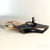
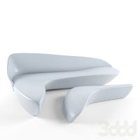
Sova Design/Rev coffee table
... table
3ddd
журнальный
https://www.facebook.com/media/set/?set=a.514295972031044.1073741841.343660145761295&type;=3
turbosquid
$30
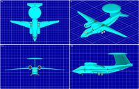
An-71 Madcap (Rev) AEW Aircraft Solid Assembly Model
... available on turbo squid, the world's leading provider of digital 3d models for visualization, films, television, and games.
turbosquid
$30

Yak-44 (Rev) AEW Aircraft Solid Assembly Model
... available on turbo squid, the world's leading provider of digital 3d models for visualization, films, television, and games.
turbosquid
$30

Mitsubishi Mu-2 Aircraft Solid Assembly Model(Rev)
... available on turbo squid, the world's leading provider of digital 3d models for visualization, films, television, and games.
turbosquid
$30

Antonov An-74 (Rev} STOL Transport Aircraft Solid Assembly Model
... available on turbo squid, the world's leading provider of digital 3d models for visualization, films, television, and games.
B
3ddd
$1
B&B
...b&b
3ddd
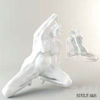
b&b italia
statue b&b italy
3ddd
$1
B&B Italia
...b&b italia
3ddd
b&b italia
b&b; italia
3ddd
$1

b&b italia
...b&b italia
3ddd
b&b italia
b&b; italia
3ddd
$1
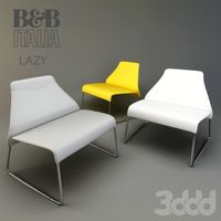
B&B LAZY
...b&b lazy
3ddd
b&b italia
b&b; lazy
3ddd
$1
B&B Italy
...b&b italy
3ddd
b&b italia
диван b&b; italy
3ddd
$1

b&b RAY
...b&b ray
3ddd
b&b italia , угловой
диван b&b; ray
3ddd
$1
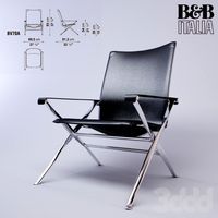
B&B Beverly
... b&b italia , beverly
cтул beverly от b&b.; текстуры в архиве
3ddd
$1

B&B ITALIA
...lia , журнальный , круглый
стол b&b; italia
3ddd
$1
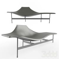
шезлонг B&B
...шезлонг b&b
3ddd
b&b italia , шезлонг
шезлонг b&b; terminal 1
3ddd
$1

B&B J.J
...b&b j.j
3ddd
b&b italia , журнальный
b&b;
j.j
45x40x49 cm