GrabCAD

STRATASATT - FDM ONE
by GrabCAD
Last crawled date: 7 years ago
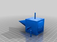
STRATASATT - FDM ONE (Stratasys Satellite Additive Technology Type - Fused Deposition Model One)
Update 6/24/15 - 12:01 Am
It's funny when you're under the gun and rush through a project the simple things you miss. I could've easily removed 75% of the assembly hardware just by putting in areas on the top and bottom panels so that they snap securely in place with the main body, leaving the only assembly hardware to be used on the front panel and to attach the solar panels to the sides. This could even have been done without compromising the design or how its 3D printed...interesting. I may have to print that bad boy out after all ; )
Entry Date:
-My entry for the Cubesat challenge.
MAIN POINTS:
-PARTS:
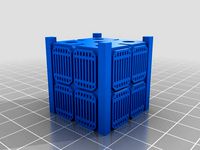
4 total FDM printed parts for structure
1 total required FDM printed switch pin for deployment operations
2-4 optional FDM printed switch pins for deployment operations
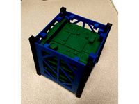
1 optional FDM printed PC/104 standoff plate
1 optional FDM printed 14mm or 27mm coupler for 2U structure
2 optional FDM printed 14mm or 27mm coupler for 3U structure
Assembly hardware - commercial over the counter nuts and bolts
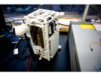
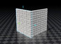
- SUPPORTLESS FDM 3D PRINTING taking advantage of such characteristics as the 45 degree overhang rule and hollow arc features. I did design however in my own support structures into the base of the main body to ensure proper printing and did a test on my own FDM printer to make sure it functioned as intended. I would imagine that the appropriate material to be used would be something that would meet the necessary criteria such as Ultem 9085 or 1010, but honestly I feel that decision should be left up to the folks with more experience using these types of materials.
- CHARACTERISTICS:
Center of Gravity: x:0.02 y:-0.70 z:0.88
Mass as Solid: 181.72 grams
Mass as FDM printed %20 infill with .2mm layer height with 2 shells: 161.57g (as per Makerware with PLA filament)
Volume: 178699.90 cubic mm
Surface area: 146936.56 square mm
-ASSEMBLY:
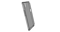
The structure was designed to be robust and strong and also able to be dissembled if necessary and inexpensive to put together. So rather than use heat stake fastening systems or create geometries that would either break off easily of create a permanently fastened structure, I opted to use COTS (commercial over the shelf) fasteners. The screws that hold the external devices such as the solar panels SELF_THREAD in the enclosure (this essentially operates similar to heat staking without the added cost and post processing time). The hardware that secures the structure together are 0-80 screws with 0-80 which are PRESS-FIT into the top and bottom panels and 2U&3U adapter plates. Stake fasteners CAN be used however I feel they are unnecessary. Another point I would like to make is on my reasoning for using nuts and bolts as opposed creating geometries that more or less "snap-fit" together. The material area available to create these types of features is very limited which in my opinion would naturally limit the strength of the fastening mechanisms' holding power. At the end of the day, if this was my payload going into space I personally would prefer solid steel nuts and bolts over plastic tabs or clips any day.
-SPECIFICATIONS:
PC/104 - The structure was designed to meet the PC/104 circuit board and module stack specification found here: http://pc104.org/wp-content/uploads/2015/02/PC104_Spec_v2_6.pdf
ISIPOD Deployment System - The structure was designed to meet the size requirements to fit with the size specifications found within the ISIPOD spec. found here: http://www.spaceflightindustries.com/wp-content/uploads/2015/05/SPUG-RevF.pdf
WEIGHT & SIZE: The structure was designed as per the cubesat specifications ver 12 found here: https://www.qb50.eu/index.php/tech-docs/category/13-extras?download=44:calpoly-cubesat-design-specification-rev-12
If I left off anything important, I'll update it here and in other images
A few thoughts:
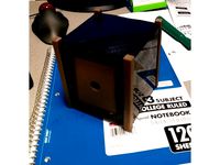
I wanted to create a solid structure using FDM printing methods that was both solid, functional, and adaptable as well as modern and very good looking (color printing readily available but even solid black would still look nice). Most if not all of the current structures (whether skeletonized or solid) are only made that way for practical purposes using typical technologies such as metal forming or stamping. They also have a pretty dated, tired and quite unattractive appearances. 3D printing opens up an entirely new opportunity within the Cubesat arena to not only possibly provide a new Cubesat structure, but one for the modern world. I chose to try and come up with an FDM solution and stayed away form the DMLS stuff simply because it's way too expensive (I imagine it would cost somewhere between $10,000-20,000 to create even a basic skeletonized structure using that method. My only issue with using an FDM model is that since it is essentially plastic, there is no radiation protection that can be had with 2mm thick sheet metal which is apparently the thinnest that folks are using to protect the internal components these days. Even though you can easily apply something like Electrolube to the body (except the rails) to protect against RF interference, I don't quite know what you can do about the radiation issue. In any case. This is my design. I'm very happy with it. Worst case it would make an awesome pencil holder for my desk.
Update 6/24/15 - 12:01 Am
It's funny when you're under the gun and rush through a project the simple things you miss. I could've easily removed 75% of the assembly hardware just by putting in areas on the top and bottom panels so that they snap securely in place with the main body, leaving the only assembly hardware to be used on the front panel and to attach the solar panels to the sides. This could even have been done without compromising the design or how its 3D printed...interesting. I may have to print that bad boy out after all ; )
Entry Date:
-My entry for the Cubesat challenge.
MAIN POINTS:
-PARTS:
4 total FDM printed parts for structure
1 total required FDM printed switch pin for deployment operations
2-4 optional FDM printed switch pins for deployment operations
1 optional FDM printed PC/104 standoff plate
1 optional FDM printed 14mm or 27mm coupler for 2U structure
2 optional FDM printed 14mm or 27mm coupler for 3U structure
Assembly hardware - commercial over the counter nuts and bolts
- SUPPORTLESS FDM 3D PRINTING taking advantage of such characteristics as the 45 degree overhang rule and hollow arc features. I did design however in my own support structures into the base of the main body to ensure proper printing and did a test on my own FDM printer to make sure it functioned as intended. I would imagine that the appropriate material to be used would be something that would meet the necessary criteria such as Ultem 9085 or 1010, but honestly I feel that decision should be left up to the folks with more experience using these types of materials.
- CHARACTERISTICS:
Center of Gravity: x:0.02 y:-0.70 z:0.88
Mass as Solid: 181.72 grams
Mass as FDM printed %20 infill with .2mm layer height with 2 shells: 161.57g (as per Makerware with PLA filament)
Volume: 178699.90 cubic mm
Surface area: 146936.56 square mm
-ASSEMBLY:
The structure was designed to be robust and strong and also able to be dissembled if necessary and inexpensive to put together. So rather than use heat stake fastening systems or create geometries that would either break off easily of create a permanently fastened structure, I opted to use COTS (commercial over the shelf) fasteners. The screws that hold the external devices such as the solar panels SELF_THREAD in the enclosure (this essentially operates similar to heat staking without the added cost and post processing time). The hardware that secures the structure together are 0-80 screws with 0-80 which are PRESS-FIT into the top and bottom panels and 2U&3U adapter plates. Stake fasteners CAN be used however I feel they are unnecessary. Another point I would like to make is on my reasoning for using nuts and bolts as opposed creating geometries that more or less "snap-fit" together. The material area available to create these types of features is very limited which in my opinion would naturally limit the strength of the fastening mechanisms' holding power. At the end of the day, if this was my payload going into space I personally would prefer solid steel nuts and bolts over plastic tabs or clips any day.
-SPECIFICATIONS:
PC/104 - The structure was designed to meet the PC/104 circuit board and module stack specification found here: http://pc104.org/wp-content/uploads/2015/02/PC104_Spec_v2_6.pdf
ISIPOD Deployment System - The structure was designed to meet the size requirements to fit with the size specifications found within the ISIPOD spec. found here: http://www.spaceflightindustries.com/wp-content/uploads/2015/05/SPUG-RevF.pdf
WEIGHT & SIZE: The structure was designed as per the cubesat specifications ver 12 found here: https://www.qb50.eu/index.php/tech-docs/category/13-extras?download=44:calpoly-cubesat-design-specification-rev-12
If I left off anything important, I'll update it here and in other images
A few thoughts:
I wanted to create a solid structure using FDM printing methods that was both solid, functional, and adaptable as well as modern and very good looking (color printing readily available but even solid black would still look nice). Most if not all of the current structures (whether skeletonized or solid) are only made that way for practical purposes using typical technologies such as metal forming or stamping. They also have a pretty dated, tired and quite unattractive appearances. 3D printing opens up an entirely new opportunity within the Cubesat arena to not only possibly provide a new Cubesat structure, but one for the modern world. I chose to try and come up with an FDM solution and stayed away form the DMLS stuff simply because it's way too expensive (I imagine it would cost somewhere between $10,000-20,000 to create even a basic skeletonized structure using that method. My only issue with using an FDM model is that since it is essentially plastic, there is no radiation protection that can be had with 2mm thick sheet metal which is apparently the thinnest that folks are using to protect the internal components these days. Even though you can easily apply something like Electrolube to the body (except the rails) to protect against RF interference, I don't quite know what you can do about the radiation issue. In any case. This is my design. I'm very happy with it. Worst case it would make an awesome pencil holder for my desk.
Similar models
grabcad
free

Palacita Tubegun
...>
<br />the file aren't accurate but feel free to improve my design and please upload here your design my friend
grabcad
free

Keyshot 4 Toon Render
...uot; rel="nofollow" target="_blank">steel construction factory</a> by kuntay cem tezcan
<br />
grabcad
free

rotary and linier motion
...uot;nofollow" target="_blank">http://members.westnet.com.au/dps/pistonandrotation/rotationpiston.html</a>
grabcad
free

Цифровой датчик температуры и влажности DHT22
...lt;a href="http://vk.com/simplab" rel="nofollow" target="_blank">http://vk.com/simplab</a>
grabcad
free

The Blue Angel
... /><br />likes are appreciated...<br />keep sharing fun and alive>>><br />download=like
grabcad
free

CNS ZN-15 36 CAL. RİFLİNG FULL ASSEMBİLİNG
...e.com/watch?v=vcw2mayopys</a>
<br />
<br />
<br />!!! videos of all the drawings of guns in this link !!!
grabcad
free

Круглый белый светодиод
...lt;a href="http://vk.com/simplab" rel="nofollow" target="_blank">http://vk.com/simplab</a>
grabcad
free

Дисплей OLED 1,3'
...lt;a href="http://vk.com/simplab" rel="nofollow" target="_blank">http://vk.com/simplab</a>
grabcad
free

Датчик пульса
...lt;a href="http://vk.com/simplab" rel="nofollow" target="_blank">http://vk.com/simplab</a>
grabcad
free

3D Monitor
...;a href="https://grabcad.com/library/uzi-pen-1" rel="nofollow" target="_blank">uzi pen</a>
Cubesat
thingiverse
free

CubeSat
...cubesat
thingiverse
cubesat structure w/ space for placing raspberry pi camera.
10x10x10cm
m3 screws.
thingiverse
free

CubeSat by 5665
...cubesat by 5665
thingiverse
cube sat
thingiverse
free
CubeSat by Novitas3d
... astronomy. i'm new in designing, so i hope that when i'll be better i'll publish a new version. print with supports.
thingiverse
free

Aerostat cubesat by michaelchen0220
...sat by michaelchen0220
thingiverse
modular aerostat instrument box. more parts coming up. general framework reference coming up.
thingiverse
free
1U CubeSat by TJEmsley
...terior of the satellite.
the brown panel in the cutaway side was a scrap from a previous design and not included in the stl file.
thingiverse
free

Universal 2U Cubesat by Juliano85
...d inserts for the raspberry pi cam v2 module.
please refer to the instructions below on assembly, and selection of configuration.
thingiverse
free
1U Cubesat model v3 by TJEmsley
...;ll need to print 5 or 6 circuit cards to fill the cube. you can use one of the circuit cards for the bottom instead of a cover.
thingiverse
free
SPEX Mini Cubesat Keychain by wkomm1
... dimensions, it is entirely made from scratch and my imagination.
here is a video of it in action: https://youtu.be/k6n3dkmdlpe
thingiverse
free
CubeSat HAB STRATO - MkV by rricup
...ter, magnetometer, compass, gps, and a 360 degree samsung camera. the flight footage is found here: https://youtu.be/-ry8s5ulqqc.
thingiverse
free

ArduSat - The Arduino CubeSat Satellite (full scale model) by MAKERFAM
...n-space?ref=live
https://www.facebook.com/pages/nanosatisfi/307866409295499
http://www.youtube.com/user/nanosatisfi?feature=watch
Fdm
3d_export
$15
old brick wall with corner version
...texture + corner version. miniatures printing - resin & fdm ...
3d_export
$5

shutter shade sunglasses
...shutter shade sunglasses 3dexport this model suitable for fdm printer, the gaps between two dynamic part is 0.4...
3d_export
$5

toggle clamp
...model to your favorite size. this model design for fdm 3d printing plus it design with standard sheet metal...
3d_export
$10

cute kitten v2 stl 3d print model
...kitten v2 stl 3d print model 3dexport solid type (fdm and hollow type (sla & dlp)<br>stl file for 3d...
3d_export
free

Articulated centipede
...actual scale is the smallest scale i've tried for fdm with perfect results. you can scale it up with...
3d_export
$5
groot con grabadora
...is recommended to print these models with a good fdm printer by using some supports enabled, however you can...
3d_export
$5

deer christmas 3
...is recommended to print these models with a good fdm printer by using some supports enabled, however you can...
3d_export
$5

deer christmas 2
...is recommended to print these models with a good fdm printer by using some supports enabled, however you can...
3d_export
$5

deer christmas
...is recommended to print these models with a good fdm printer by using some supports enabled, however you can...
3d_export
$5

deer christmas 5
...is recommended to print these models with a good fdm printer by using some supports enabled, however you can...
One
turbosquid
$2
one plus one
... available on turbo squid, the world's leading provider of digital 3d models for visualization, films, television, and games.
3ddd
$1
One
...one
3ddd
стул
офисный стул one
3ddd
free

one
...
palazetti one ,http://palazzetti.ca/index.php/component/virtuemart/seating/armchairs-lounges/one-chair-detail?itemid=0
turbosquid
$35

One A
... available on turbo squid, the world's leading provider of digital 3d models for visualization, films, television, and games.
turbosquid
free
One
... available on turbo squid, the world's leading provider of digital 3d models for visualization, films, television, and games.
3ddd
$1
Стул One
...стул one
3ddd
one , magis
кресло magis s.p.a , one
3ddd
$1
Стул One
...стул one
3ddd
one , magis
кресло one chair (4star), magis s.p.a.
3d_export
$20
xbox one
...xbox one
3dexport
xbox one
3ddd
$1
xbox one
... консоль , джойстик
xbox one + kinect + gamepad
3ddd
free
One
...nstantin grcic
артикул ct-284 (cosmorelax.ru)
размер l36xw41xh82.5, sh 77cm
цвет черный, красный
материал алюминий
вес 2,5 кг