Thingiverse
Revised Auger for Filastruder Auger Assisted Vertical Hopper by mrflippant
by Thingiverse
Last crawled date: 3 years, 3 months ago
ALERT!
This auger can be used with any version of the Auger Assisted Vertical Hopper (see Remix Source) parts, however, if you plan to use this auger, and have not already printed other hopper parts, printing the included bushing and hopper body will make your life measurably easier. Note that the hopper has channels to allow the screws in this auger to easily pass through, and the thread is reversed so that high torque does not unscrew the bushing. Consequently, the included bushing is required to mate with the reversed thread in the main body. Ideally, when using this auger, you are using the included hopper body and bushing models as well.
BACKGROUND
I prefer the vertical set up for efficient use of space, and because gravity becomes the pulling force to stretch out the hot filament, so a vertical hopper was the main option for my Filastruder. Recycled material, not being consistent in shape and size, would need assistance on it's way through the hopper and into the extruder. CNC Kitchen (YouTube) already showed that vibration is not enough to keep recycled scrap material moving into the extruder with this kind of arrangement. And so, the Auger Assisted Vertical Hopper by universaljoint was a "no-brainer" solution.
This is my third design after two previous revisions that didn't work so well. The first was not enough agitation and no movement at the bottom of the hopper, and the second was too much pressure. This iteration has a combination of those ideas, using pure agitation for the majority of the auger, but with a short amount of thread at the very end, right up near the Filastruder entry point, for the final push into the extruder auger.
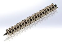
As you have probably already seen from the photographs, this auger uses screws through the shaft to agitate the material and half an auger thread at the end to make sure the material that gets that far is pushed into the Filastruder auger. In order to get the best, and most complete agitation of material by the screws, they must be nearly touching the inner wall of the hopper chamber, so as not to leave so much material hung up on the printed walls. The problem is, with the original hopper body, the auger won't fit into hopper if the screws are all the way out as far as they need to be. I've included an alternate hopper body to make this easier to assemble and service, but this auger can still be used if you printed another version of the hopper body. Here is the recommended process to be followed:
ASSEMBLY
IT IS RECOMMENDED that you print the included versions of the hopper main body and the auger bushing, instead of the originals. However, you can still use this auger with the original models, with a little extra work. You can also modify the original body by cutting into the threads to make channels. Refer to the hopper body model for my recommendation on where to put the channels.
Print the auger model. PLA is fine. I used PETG.
Assemble the two halves of the auger. Note that there are 2mm pin holes, one at the tip, and two at the base, to insert 1.75mm filament pins for easier alignment while gluing. Don't forget to install the square nut at the base before gluing!!
Using M3 screws of sufficient length (M3x25mm is good, round or button head recommended), drive them into the holes that go all the way through the shaft. If you printed the included hopper body (ABS!), the screws need to be driven through so that the top of the screw head is 11.5mm from the surface of the shaft. A depth pin on a set of calipers is a good way to gauge it. The top of the head will be brushing the inside of the hopper body, so if it's too high, it will bind. If it's too low, you might have material stuck on the inside of the hopper. Alternating which side you drive them in is also recommended.
Assemble the auger assembly, with the bushing and the large gear. A little bit of SuperLube (or similar) on the inside of the bushing, or the mating surface of the auger shaft, will make the system work nicely and with much less noise. Skip the next two steps if you printed the included hopper body.
If you did not print my updated hopper main body, you'll need to drive each screw until it is about halfway through the shaft. The goal is to make it fit through the threaded auger opening in the hopper main body. If you don't drive them far enough through the auger shaft, you won't be able to fit them through the threads. Depending on the type of screw head and length of the screw, you might need to insert the screws into the auger shaft AFTER it's in the hopper main body, through the hopper opening.
As you insert the auger into the hopper, use a long hex driver to UNSCREW the M3 screws, one at a time. Measure the distance between the top of the screw head and the surface of the auger shaft to be 11.5mm (less is ok, but more will cause binding problems) before moving to the next screw. Don't unscrew any of the next ones until you're confident that the ones you've already done are where you want them, because you'll have to screw them back in just to access a previously unscrewed screw. (LOL) Trust me, you'll figure this out quick. It was my idea, and I still had to mess around with each screw for a few minutes. Again, printing the included hopper body will make your life WAY easier.
Fully install the auger by screwing the bushing into the hopper main body. In the end, every screw should be just touching, or slightly above, the inside of the auger chamber as it turns around. This is to help keep material moving down the shaft rather than sticking to the walls.
Plug everything back together and get to extruding! And LMK if you run into any issues!
PHOTOS
In case any of the photos are not self explanatory, here's what they show:
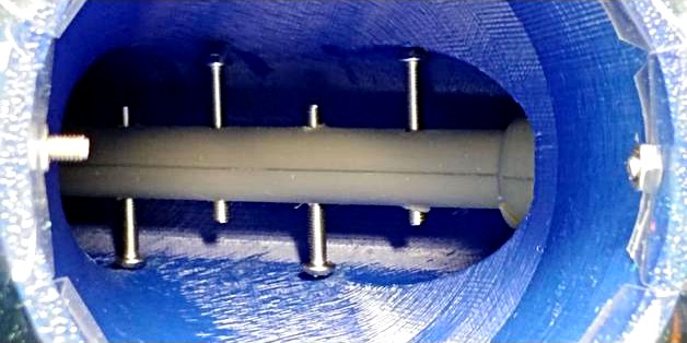
Installed auger, looking into the hopper. You can see that the screws protrude through the other side of the shaft. That's a good thing. We don't want more places for plastic particles to get stuck, and more agitation isn't a bad thing. The important thing is that the screw heads are not pressed against the inside of the hopper chamber, but merely skimming it.
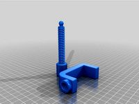
Printed auger model
Auger assembly with bushing and gear, ready to install. Note that the screws are pre-installed and set to the correct distance, for installation into the included hopper main body model with channels for the screw heads. If you're using this with an earlier hopper main body print, you'll need to install the screws as you insert the auger. I decided to go ahead and re-print the main body because it just makes this whole thing easier, not to mention cleaning and replacing things down the road.
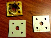
Print of revised hopper main body showing the channels for the screw heads to pass through the bushing threads.
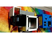
Inserting the auger with screws installed into the new main body. Easy peasy lemon squeezy! :)
When using the original hopper main body, this is showing how I install the screws with a long hex driver. Remember, start with the one nearest the tip, and test each one before moving to the next one! You can avoid this fiddly step if you print the included hopper main body (and the bushing!)
FILES
Hopper_Auger_Long_V2.stl - This is the operative part. It's in two parts in order for clean printing. With good elephant's foot compensation you should be able to print it, pull it off the plate, and assemble it with no trimming needed. Otherwise, remove any flashing.
Filastruder_vertical_auger_assisted_hopper_V1_main_G4.stl - This is a new version of the hopper main body with slots on two sides of the thread for the auger bushing to make it easier to assemble the whole system. If you haven't already printed the main body, and intend to use this auger, this is the main body model you want to print. I wish I'd printed it. ;-) ABS is recommended. The threads for the bushing have been reversed to help make sure it stays screwed tight during use.
Filastruder_vertical_auger_assisted_hopper_V1_auger_bushing_low-tolerance.stl - This is a revised bushing for the auger with a lower tolerance between the auger and the inner diameter of the bushing. This reduces the play in the auger, and can reduce (though not eliminate) the "crunching" of material in the hopper. A little bit of SuperLube (or similar) inside the bushing, or on the mating surface of the auger, will make this work nicely. This also has reversed threading, to match the reversed threading of the revised hopper main body.
EPILOGUE
If you're not already a member, and you're working on your own filament extrusion system, even if it's not a Filastruder, PLEASE join our 3D Printer Filament Recycler Group on Facebook!
Video of testing this version prior to successful extrusion run.https://youtu.be/vNp37S3AhYA
This auger can be used with any version of the Auger Assisted Vertical Hopper (see Remix Source) parts, however, if you plan to use this auger, and have not already printed other hopper parts, printing the included bushing and hopper body will make your life measurably easier. Note that the hopper has channels to allow the screws in this auger to easily pass through, and the thread is reversed so that high torque does not unscrew the bushing. Consequently, the included bushing is required to mate with the reversed thread in the main body. Ideally, when using this auger, you are using the included hopper body and bushing models as well.
BACKGROUND
I prefer the vertical set up for efficient use of space, and because gravity becomes the pulling force to stretch out the hot filament, so a vertical hopper was the main option for my Filastruder. Recycled material, not being consistent in shape and size, would need assistance on it's way through the hopper and into the extruder. CNC Kitchen (YouTube) already showed that vibration is not enough to keep recycled scrap material moving into the extruder with this kind of arrangement. And so, the Auger Assisted Vertical Hopper by universaljoint was a "no-brainer" solution.
This is my third design after two previous revisions that didn't work so well. The first was not enough agitation and no movement at the bottom of the hopper, and the second was too much pressure. This iteration has a combination of those ideas, using pure agitation for the majority of the auger, but with a short amount of thread at the very end, right up near the Filastruder entry point, for the final push into the extruder auger.
As you have probably already seen from the photographs, this auger uses screws through the shaft to agitate the material and half an auger thread at the end to make sure the material that gets that far is pushed into the Filastruder auger. In order to get the best, and most complete agitation of material by the screws, they must be nearly touching the inner wall of the hopper chamber, so as not to leave so much material hung up on the printed walls. The problem is, with the original hopper body, the auger won't fit into hopper if the screws are all the way out as far as they need to be. I've included an alternate hopper body to make this easier to assemble and service, but this auger can still be used if you printed another version of the hopper body. Here is the recommended process to be followed:
ASSEMBLY
IT IS RECOMMENDED that you print the included versions of the hopper main body and the auger bushing, instead of the originals. However, you can still use this auger with the original models, with a little extra work. You can also modify the original body by cutting into the threads to make channels. Refer to the hopper body model for my recommendation on where to put the channels.
Print the auger model. PLA is fine. I used PETG.
Assemble the two halves of the auger. Note that there are 2mm pin holes, one at the tip, and two at the base, to insert 1.75mm filament pins for easier alignment while gluing. Don't forget to install the square nut at the base before gluing!!
Using M3 screws of sufficient length (M3x25mm is good, round or button head recommended), drive them into the holes that go all the way through the shaft. If you printed the included hopper body (ABS!), the screws need to be driven through so that the top of the screw head is 11.5mm from the surface of the shaft. A depth pin on a set of calipers is a good way to gauge it. The top of the head will be brushing the inside of the hopper body, so if it's too high, it will bind. If it's too low, you might have material stuck on the inside of the hopper. Alternating which side you drive them in is also recommended.
Assemble the auger assembly, with the bushing and the large gear. A little bit of SuperLube (or similar) on the inside of the bushing, or the mating surface of the auger shaft, will make the system work nicely and with much less noise. Skip the next two steps if you printed the included hopper body.
If you did not print my updated hopper main body, you'll need to drive each screw until it is about halfway through the shaft. The goal is to make it fit through the threaded auger opening in the hopper main body. If you don't drive them far enough through the auger shaft, you won't be able to fit them through the threads. Depending on the type of screw head and length of the screw, you might need to insert the screws into the auger shaft AFTER it's in the hopper main body, through the hopper opening.
As you insert the auger into the hopper, use a long hex driver to UNSCREW the M3 screws, one at a time. Measure the distance between the top of the screw head and the surface of the auger shaft to be 11.5mm (less is ok, but more will cause binding problems) before moving to the next screw. Don't unscrew any of the next ones until you're confident that the ones you've already done are where you want them, because you'll have to screw them back in just to access a previously unscrewed screw. (LOL) Trust me, you'll figure this out quick. It was my idea, and I still had to mess around with each screw for a few minutes. Again, printing the included hopper body will make your life WAY easier.
Fully install the auger by screwing the bushing into the hopper main body. In the end, every screw should be just touching, or slightly above, the inside of the auger chamber as it turns around. This is to help keep material moving down the shaft rather than sticking to the walls.
Plug everything back together and get to extruding! And LMK if you run into any issues!
PHOTOS
In case any of the photos are not self explanatory, here's what they show:
Installed auger, looking into the hopper. You can see that the screws protrude through the other side of the shaft. That's a good thing. We don't want more places for plastic particles to get stuck, and more agitation isn't a bad thing. The important thing is that the screw heads are not pressed against the inside of the hopper chamber, but merely skimming it.
Printed auger model
Auger assembly with bushing and gear, ready to install. Note that the screws are pre-installed and set to the correct distance, for installation into the included hopper main body model with channels for the screw heads. If you're using this with an earlier hopper main body print, you'll need to install the screws as you insert the auger. I decided to go ahead and re-print the main body because it just makes this whole thing easier, not to mention cleaning and replacing things down the road.
Print of revised hopper main body showing the channels for the screw heads to pass through the bushing threads.
Inserting the auger with screws installed into the new main body. Easy peasy lemon squeezy! :)
When using the original hopper main body, this is showing how I install the screws with a long hex driver. Remember, start with the one nearest the tip, and test each one before moving to the next one! You can avoid this fiddly step if you print the included hopper main body (and the bushing!)
FILES
Hopper_Auger_Long_V2.stl - This is the operative part. It's in two parts in order for clean printing. With good elephant's foot compensation you should be able to print it, pull it off the plate, and assemble it with no trimming needed. Otherwise, remove any flashing.
Filastruder_vertical_auger_assisted_hopper_V1_main_G4.stl - This is a new version of the hopper main body with slots on two sides of the thread for the auger bushing to make it easier to assemble the whole system. If you haven't already printed the main body, and intend to use this auger, this is the main body model you want to print. I wish I'd printed it. ;-) ABS is recommended. The threads for the bushing have been reversed to help make sure it stays screwed tight during use.
Filastruder_vertical_auger_assisted_hopper_V1_auger_bushing_low-tolerance.stl - This is a revised bushing for the auger with a lower tolerance between the auger and the inner diameter of the bushing. This reduces the play in the auger, and can reduce (though not eliminate) the "crunching" of material in the hopper. A little bit of SuperLube (or similar) inside the bushing, or on the mating surface of the auger, will make this work nicely. This also has reversed threading, to match the reversed threading of the revised hopper main body.
EPILOGUE
If you're not already a member, and you're working on your own filament extrusion system, even if it's not a Filastruder, PLEASE join our 3D Printer Filament Recycler Group on Facebook!
Video of testing this version prior to successful extrusion run.https://youtu.be/vNp37S3AhYA
Similar models
thingiverse
free

Filastruder alignment cone by tonycstech
...he drillbit rotate around the center and not scraping off the walls creating flakes that get extruder nozzle stuck when printing.
thingiverse
free

Cooling Unit for Filastruder Fume Extraction Enclosure by mrflippant
...print without support.
you'll need parts from the fume extraction enclosure that this is remixed from to complete the system.
thingiverse
free

Vanagon Front Lower Grill Clip by fhferret
... through the plastic grill and then through the hole in the body. tighten up the screw to expand the clip and you should be good.
thingiverse
free

Cam/Light Tripod Pivot Head by Thomllama
... i'll likely edit the pivot so all the crappy supports aren't needed that scar up the bottom (as you can see in my image)
thingiverse
free

Removable Filastruder Hopper With Bottle Fitting by imageit
...imageit
thingiverse
removable filastruder hopper with bottle fitting.
allows regular cylindrical top fitting or screw in bottle.
grabcad
free

Screwdriver
...typical simple screwdriver has a handle and a shaft, ending in a tip the user puts into the screw head before turning the handle.
thingiverse
free

Filastruder Hopper with Window by Celcius1
...to clear the main body of the filastruder. i also put a locating collar on the bracket to ensure it stays in the right position.
grabcad
free

Hopper Assembly
...or transferring bolts from heading machines to the threading machines. this machine is used for automation in bolt manufacturing.
thingiverse
free
Revised Clamp by Hank106
...lamp body to stabilize the threaded shaft. extended the threaded shaft. use foot from original author's design to complete.
thingiverse
free

Zeepro Bushing by scherle
...#39;t need the nuts at all).
just install 1 bushing at each end of each rod to prevent it from sliding and you're good to go.
Mrflippant
thingiverse
free

Auger Fail V1 by mrflippant
...int or use this model! it doesn't work as well as i'd wanted.
use this instead: https://www.thingiverse.com/thing:4687089
thingiverse
free

Pancasila Ear Saver Mask Relief Strap by mrflippant
...pancasila ear saver mask relief strap by mrflippant
thingiverse
pancasila ear saver mask relief strap
thingiverse
free

Altoids Tin Nozzle Holder by mrflippant
... wanted one with the variety i had, plus more nozzles, and more for 0.4mm nozzles, as well as lines between them. here we are. :)
thingiverse
free

1/32 The Stig with chin support and standing base by mrflippant
...single support for the chin of the helmet. i printed this as-is on my elegoo mars pro and had only to remove that single support.
thingiverse
free

Transformers Autobot Ear Saver Mask Relief Strap by mrflippant
....thingiverse.com/thing:1131435
(for some reason, my original thing doesn't show up in my list of creations, so i re-upped it)
thingiverse
free

Dog Bone Magnet Fidget by mrflippant
...r you do one of the halves, otherwise it will be the same polarity between the two faces, and the fidget won't work properly.
thingiverse
free

Filastruder Drilling Templates by mrflippant
... bolts.
hopefully this doesn't happen to you, but this will make it easy to add new holes to remedy the situation if it does.
thingiverse
free
Filastruder Skeleton Frame by mrflippant
... won't let me link the back plate model i used for the fan bracket, so here that is.https://www.thingiverse.com/thing:2781444
thingiverse
free

Ninco Go Kart Parts by mrflippant
... frame. most of the parts will need some kind of glue, either for assembly (the wing) or to the kart to keep it on during racing.
thingiverse
free

Pelletizer for 3/4" Router Bit by mrflippant
...l press so that it's all nice and solid.
bosch 3/4-in carbide-tipped straight router bithttps://www.amazon.com/dp/b000gybtiw
Filastruder
thingiverse
free
filastruder by Ulises
...filastruder by ulises
thingiverse
soporte para sujetar la camisa de la filastruder
thingiverse
free

Filastruder hopper extension by jesse
...filastruder hopper extension by jesse
thingiverse
doubles the height of the rectangular filastruder hopper
thingiverse
free

Official Filastruder Enclosure by OSPrinting
...e official filastruder enclosure. this is everything you need to turn your diy filastruder kit into a lean mean fighting machine.
thingiverse
free

Filastruder Vertical Chute by kayo
...filastruder vertical chute by kayo
thingiverse
just yet another chute for filastruder with extended sink.
thingiverse
free

Filastruder simple Guide by Baselalmualim
...filastruder simple guide by baselalmualim
thingiverse
filastruder simple guide use a wier to guide your filament easily
thingiverse
free

Filastruder Tripod Adapter by kbowen99
... for an adjustable angle to find the best mount. it uses an m8 bolt & nut to mount the filastruder. it is surprisingly secure
thingiverse
free

Compact Electronics Enclosure for Filastruder by fyzasidek
...compact electronics enclosure for filastruder by fyzasidek
thingiverse
compact electronics enclosure for filastruder
thingiverse
free

Filastruder Hopper Version 2 by deflore
...filastruder hopper version 2 by deflore
thingiverse
this was designed to use with filastruder v2 vertically
thingiverse
free

Filastruder Electronics Faceplate by cahorton
...mperature regulator and two switches that make up the filastruder v1 controls. it is designed to be screwed onto the base board.
thingiverse
free

FIlastruder Electronics cover by ObfuscatedDevices
... of a cover design for the filastruder electronics cover. i've included a support structure so it can be printed in one pass.
Auger
3d_export
$10
auger screw
...auger screw
3dexport
this stainless steel auger screw is used for inclined screw conveyors.
turbosquid
$6

Auger Dining Room Set
... available on turbo squid, the world's leading provider of digital 3d models for visualization, films, television, and games.
3d_export
$49

auger header-tin fronts
... in this model, please do not hesitate to contact us, we are looking forward to continuously dealing with you.<br>markos 3d
3d_export
$21
hole digger auger soil drill hand held machine for earth ground
... consists of a rotating vertical metal rod or pipe with one or more blades attached at the lower end, that cut or scrape the soil
archibase_planet
free
Drill
...drill archibase planet perforator drill auger drill 3 - 3d model (*.gsm+*.3ds) for interior 3d...
archive3d
free

Drill 3D Model
...drill 3d model archive3d perforator drill auger drill 3 - 3d model (*.gsm+*.3ds) for interior 3d...
3d_export
$10

BOSCH cordless screwdriver IXO 3D Model
...ixo screws construction worker house work bricolage screwing drill auger borer burr wimble gimlet percussion bosch cordless screwdriver ixo...
3d_export
$149

S96 Combine with Corn Harvester Head
...row units transmission<br>crop divider (cutting bar fingers)<br>harvester lights<br>header platform<br>platform auger (helical conveyor)<br>row units transmission<br>rubber pipes for feeder house<br>tilt feeder...
thingiverse
free

Auger by bsikes09
...auger by bsikes09
thingiverse
auger
thingiverse
free
Auger by johannchopper
...uger by johannchopper
thingiverse
auger that will fit a pvc t-piece. will be used in a doggy feeder project that i am busy with.
Hopper
3d_export
$5

hopper
...hopper
3dexport
hopper
design_connected
$16

Hopper
...hopper
designconnected
minotti hopper lounge chairs computer generated 3d model. designed by rodolfo dordoni.
turbosquid
$73

Hopper
...
turbosquid
royalty free 3d model hopper for download as obj on turbosquid: 3d models for games, architecture, videos. (1464144)
turbosquid
free

hopper
... available on turbo squid, the world's leading provider of digital 3d models for visualization, films, television, and games.
3ddd
$1
Extremis HOPPER
... hopper , скамья
высота: 750мм
ширина: 2400мм
глубина: 690мм
3d_export
$6
hopper roller conveyor
...hopper roller conveyor
3dexport
hopper roller conveyor
turbosquid
$6
twister hopper
...uid
royalty free 3d model twister hopper for download as stl on turbosquid: 3d models for games, architecture, videos. (1338460)
turbosquid
$40

Hopper Cars
... available on turbo squid, the world's leading provider of digital 3d models for visualization, films, television, and games.
turbosquid
$20

Miedema Hopper
... available on turbo squid, the world's leading provider of digital 3d models for visualization, films, television, and games.
turbosquid
free

Garbage Hopper
... available on turbo squid, the world's leading provider of digital 3d models for visualization, films, television, and games.
Revised
turbosquid
$40

counter display revised
... available on turbo squid, the world's leading provider of digital 3d models for visualization, films, television, and games.
3d_export
$10

room interior design model 001
...for the revision by contact me with email, i will do it with pleasure.<br>thanks for support<br>i hope you like it :)
3d_export
$15

engineering drone scifi
...gged in blender. textured in substance painter.<br>textures: main mat, second mat - 4096x4096<br>glass mat - 512x512.
cg_studio
$30

Apple iphone 4 Cell Phone LAST revision3d model
...4d .wrl .wrz - apple iphone 4 cell phone last revision 3d model, royalty free license available, instant download after purchase.
3d_export
$7

ficus alii plant
...lt;br>color:<br>description<br>ficus plants ,,, small revisions in modeling ,,, max2015,2012 & fbx ,, enjoyyyy
3d_export
$10

antonio lupi design timbro
...quotation of the fifties but the style has been revised in a contemporary design. romantic and elegant taste is...
3d_export
free

bed - sample
...gt;- reupload with new fbx format.<br>- edge loops added for better shading.<br>- fix flipped uv map in certain area.
3d_export
$60

mitsubishi galant 1996 - 1999 -- 8th generation -- sedan
...the 7th generation (compared to the 6th), the concern revised the design of the new generation of the galant,...
3d_export
$27

the latest automatic n95 mask machine production line drawings
...automatic n95 mask machine production line drawings<br>this set of revised drawings with complete circuit diagram + electrical equipment bom...
3d_export
$10
antonio lupi design timbro
...quotation of the fifties but the style has been revised in a contemporary design. romantic and elegant taste is...
Assisted
3d_export
$5

painting assistant
...painting assistant
3dexport
draw samples
3d_export
$5

assistive cane
...assistive cane
3dexport
aristocratic cane for characters
3d_export
$10

Assist bike 3D Model
...assist bike 3d model
3dexport
assist bike
assist bike 3d model modelix 59218 3dexport
turbosquid
$1

Robot Assistant
...d
royalty free 3d model 3d robot human for download as blend on turbosquid: 3d models for games, architecture, videos. (1599434)
turbosquid
$30

Galaxy Assistant's Stool
... available on turbo squid, the world's leading provider of digital 3d models for visualization, films, television, and games.
3d_export
$15

Prototype version of the robot assistant
...ersion of the robot assistant, designed to help a person in a variety of tasks, both in helping in the garden and in armed escort
turbosquid
$69

Droid Assistant
... robot guard for download as blend, dae, fbx, obj, stl, and x on turbosquid: 3d models for games, architecture, videos. (1624852)
turbosquid
free

Free Realistic Grass Assistant
...3d model free realistic grass assistant for download as blend on turbosquid: 3d models for games, architecture, videos. (1454100)
turbosquid
free

Realistic Tree Assistance Pack
...3d model realistic tree assistance pack for download as blend on turbosquid: 3d models for games, architecture, videos. (1386578)
turbosquid
$10

Generic Lab Worker / Assistant
...el generic lab worker / assistant for download as max and obj on turbosquid: 3d models for games, architecture, videos. (1212746)
Vertical
3ddd
$1
Vertical curtain
...vertical curtain
3ddd
роллеты
vertical curtain
modern curtain
design_connected
$11
Mr.Tubes Vertical
...mr.tubes vertical
designconnected
tonone mr.tubes vertical computer generated 3d model.
3ddd
free

Vertical gardening
... фитомодуль , фитостена
vertical gardening
2000x1000x165
vizpark
$5

Einstein Vertical
...tical is a set of 3d brick textures for modern buildings, including mulit-textures and 4k tileable textures with material layers.
turbosquid
$5

brazier vertical
... free 3d model brazier vertical for download as sldas and ige on turbosquid: 3d models for games, architecture, videos. (1647570)
3d_export
$40

vertical stirling engine
...vertical stirling engine
3dexport
vertical stirling engine
turbosquid
$50

Vertical Garden
... available on turbo squid, the world's leading provider of digital 3d models for visualization, films, television, and games.
turbosquid
$20

vertical flag
... available on turbo squid, the world's leading provider of digital 3d models for visualization, films, television, and games.
turbosquid
$4

vertical plant
... available on turbo squid, the world's leading provider of digital 3d models for visualization, films, television, and games.
design_connected
$11

Mr.Tubes Vertical Tapered
...mr.tubes vertical tapered
designconnected
tonone mr.tubes vertical tapered computer generated 3d model.