GrabCAD

NASA CHALLENGE - HANDRAIL CLAMP ASSEMBLY
by GrabCAD
Last crawled date: 1 year, 10 months ago
HANDRAIL CLAMP ASSEMBLY (HCA) DESCRIPTION
In the design of the handrail clamp, the following points were taken into consideration in their order of importance.
1. Safety
a. Sharp edge human factors were carefully adhered to as per CHAMP requirements with all edges rounded to appropriate radii
b. Pinch areas between moving parts were avoided wherever possible, otherwise anti-pinch shields were built-in.
c. A rigid connection between the clamp and rail was vital as described under point 2 below.
2. Function & strength
a. It was deemed of paramount importance that the assembly has a positive grip on the rail. This point is interleaved with Safety as sudden slippage or opening of the bracket is considered unsafe for the astronaut. This would be quite easily achieved with a 3 or 4 piece assembly by using cams, as is the case with the ISS current clamp assembly for example.
This design has two parts (see point 3) and this was achieved by a design with special arrangement of the clamp elements as described under OPERATION below. The object was to achieve rigidity of the clamp-rail connection at least to the level of the rail interface strength achievable with the ABS printed part.
3. Mass and form
It was decided to limit the assembly to two printed parts for simplicity of assembly for minimum astronaut time.
The shape envelope of 1” around the rail has been adhered to.
The volume of the HCA assembly is 5.42 in³, and the weight is 0.2 lb.
4. Both parts comply with the maximum print size of 2.36” x 2.36” x 4.72”.
OPERATION
The HCA is shown in Figure 1 with depicted names of various parts. Figure 1(a) is an isometric view while Figure 1(b) shows the assembly end-view as positioned on the rail in the locked position.
The part with the seat track interface is named ‘L-Track, while the bottom part is named ‘Clamp’.
After the two parts have been printed they are assembled as per Figure 2(a). The Clamp is hand-pressed into the L-Track until it snaps into position as per Figure 3(a). This is only done once, thereafter the assembly may be manipulated as an integral unit. This obviates mislaying or loosing parts.
The assembled unit may now be placed over the handrail as shown in Figure 2(c) and positioned axially on the rail as required – Figure 2(d).
Attaching the HCA assembly to the rail
The clamp is closed by pushing the Clamp on the Lock Serrations into the locked position, see Figure 1(b).
In the closing of the clamp around the rail, there are several clamping and wedging factors taking place. As the clamp ‘cam follower’ (Figure 3(c)) enters the space between the Latch and the cam surface several processes take place:
1. The Latch springs open driven by the cam follower larger radius.
2. The Clamp cam-following element, due to offset ‘e’ (Figure 3(a)), forces the cam surface element to flex and wedge its Rail Grip under the rail.
3. The lower Rail Grips (Figure 2(b)) wedge themselves at a shallow 35° (Arrows B), this in turn causes the assembly to float and wedge its tow Rail Grips on the rail at even shallower 25° (Arrows C).
The angles were more or less determined intuitively and proved satisfactory in tests on actual printed assemblies.
Similarly, the Latch spring thickness was determined during tests. These tests were done with an average female (at the risk of my wife being labeled 'average').
4. The Clamp is pushed further until the Latch snaps into the Locked position.
Figure 3(b) shows the relative position of the Latch landing to the Clamp pivot and it can be clearly seen that it would be quite difficult to force the latch open by pushing on the unlock serrations (Figure 1(b)) short of causing breakage.
5. It was found during testing that a very strong and stable attachment to the rail is achieved with normal hand pressure.
Detaching the HCA assembly
To dismount the HCA assembly from the rail it is necessary to pull the Latch while pressing down on the Unlock Serrations of the Clamp.
One easy way, it was found, is to use the thumb on the latch and the fore and middle finger, thereby unlocking the assembly with on hand.
General
It was found during tests that the snapping close of the Latch would not cause an injury of concern, however to prevent any possible discomfort, an anti-pinch shield was built in, see Figure 1(a).
Serrations were added on the Clamp to prevent finger slippage during mounting and dismounting the assembly.
There is a mid-groove on each side of the Clamp (Figure 1(a)) introduced to prevent finger slippage. This also helped in the attainment of the correct radii as required in the competition rules.
Similar models
grabcad
free

NASA CHALLENGE - HANDRAIL CLAMP ASSEMBLY
...next to the rail than further away from it. similary, the clamp widens away from the rail. this results...
grabcad
free

CHAMP 3 - NASA Handrail Clamp
...t within the build envelope in the orientation shown in the attached pictures. the print has a total volume of 2.29 cubic inches.
grabcad
free

HAL CLAMP BY GUY RAZ
...ernal stress in the assembly while increasing friction between the clamp halves and the handrail, thus immobilizing the assembly.
grabcad
free

NASA Handrail Clamp (Version 1.1)
...bending features. i think, a dimension tolerance compensation for all components is relative easy, because of using a wedge only.
grabcad
free

2 piece handrail clamp
...rs. check out the video to see how the clamp clips on and then slides along the rail and how it is secured by the locking slider.
grabcad
free

Nasa hand rail clamp assembly
...sed by astronauts on iss to provide rigid mounting locations required in a microgravity environment for normal daily operations.
grabcad
free

CHAMP-X3 NASA Handrail Clamp
...champ-x3 nasa handrail clamp
grabcad
handrail clamp with a cam-lock- 1/4 turn fastener.
grabcad
free

NASA Handrail Clamp Assembly (CHAMP)
...ction:
print each component in vertical axis or along the longest axis of the rail.
i gave my design a name, “bulldog clamp” :-p
grabcad
free

Reuleaux Triangle NASA CHAMP v1.0 and v2.0 (latest)
...functional connection points. the proposed design is using a similar to the hca opposite-to-opening locking mechanism. the decision is...
grabcad
free

CHAMP QR
.... measures 73420.47 cubic millimeters in volume.
6. self driving locating and locking mechanism, just push and lock in position.
Handrail
archive3d
free
Handrail 3D Model
...iling guard-rail
handrail stair n030114 - 3d model (*.gsm+*.3ds) for interior 3d visualization.
archive3d
free

Railing 3D Model
...railing 3d model archive3d railing handrail fence guard-rail railing n140314 - 3d model (*.gsm+*.3ds+*.max) for...
archive3d
free
Handrail 3D Model
...e3d
railing handhold parapet
handrail n050710 - 3d model (*.3ds) for interior 3d visualization.
archive3d
free
Baluster 3D Model
...baluster 3d model archive3d baluster banister handrail baluster n140911 - 3d model (*.gsm+*.3ds) for interior 3d...
archive3d
free
Rack 3D Model
...rack 3d model archive3d rack baluster banister handrail rack for stair n131011 - 3d model (*.3ds) for...
archive3d
free

Baluster 3D Model
...baluster 3d model archive3d baluster banister handrail baluster 6 - 3d model (*.gsm+*.3ds) for interior 3d...
archive3d
free

Baluster 3D Model
...baluster 3d model archive3d baluster banister handrail baluster 2 - 3d model (*.gsm+*.3ds) for interior 3d...
archive3d
free
Handrail 3D Model
...ters hand-rail railing
handrail n020710 - 3d model (*.gsm+*.3ds) for interior 3d visualization.
archive3d
free

Handrail 3D Model
...banisters railing guard-rail
handrail n070710 - 3d model (*.3ds) for interior 3d visualization.
archive3d
free
Baluster 3D Model
...baluster 3d model archive3d baluster banister handrail baluster n270313 - 3d model (*.gsm+*.3ds) for interior 3d...
Nasa
3d_ocean
$15
Stratosphere HDRI
...astronaut earth emu eva eva missions hdr hdri highres nasa outer space panorama planet refraction skydome space spaceship stars...
3d_ocean
$9

HD Earth Model
...hd earth model 3docean atmosphere clouds earth mars moon nasa ocean photorealistic planet poly realistic rock sky solar space...
3d_ocean
$9

Realistic HD Earth Model
...earth model 3docean 3dmodel atmosphere clouds earth mars moon nasa ocean photorealistic plane poly realistic rock sky solar stars...
3d_ocean
$29

Spaceship Progress Soyuz
...spaceship progress soyuz 3docean 3d cosmos iss launch mir nasa orbital rocket russian satellite ship solar space spacecraft sputnik...
3d_ocean
$5

Sun Model
...sun model 3docean atmosphere clouds mars moon nasa ocean photorealistic planet poly realistic rock sky solar space...
3d_ocean
$49
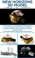
New Horizons Space Probe
...3docean astronomy astrophysics c4d cinema 4d element 3d mission nasa new horizons obj pluto satellite space space probe spacecraft...
3d_ocean
$3

Sun
...sun 3docean cosmos earth galaxy milky moon nasa planet sky space sun system universe a sun model...
3d_ocean
$6

HD Saturn Model
...hd saturn model 3docean atmosphere clouds mars moon nasa ocean photorealistic planet poly realistic rock saturn sky solar...
3d_ocean
$5

Uranus Model
...uranus model 3docean atmosphere clouds mars moon nasa ocean photorealistic planet poly realistic rock sky solar space...
3d_ocean
$12

Photoreal Earth Model
...earth model 3docean atmosphere clouds continent earth globe iss nasa ocean orbit planet science space terra turkey usa 21k...
Challenge
3d_export
$10

Dodge Challenger 1970 3D Model
...challenger 1970 3d model
3dexport
dodge challenger auto model classic old
dodge challenger 1970 3d model chernikov 64678 3dexport
3d_export
$39

Dodge Challenger 3D Model
...dodge challenger 3d model
3dexport
dodge challenger car muscle fast
dodge challenger 3d model godzik 18503 3dexport
3d_export
$99

Dodge Challenger hardtop 1970 3D Model
...ation hardtop plymouth barracuda muscle sport racing race mustang
dodge challenger hardtop 1970 3d model humster3d 50000 3dexport
3d_ocean
$25

Mopar Dodge Challenger wheel
... has got physically accurate materials. it is separated on parts and they are correctly named. so it is easy to use and modify...
3d_ocean
$85

Mad Max Fight Interceptor Dodge Challenger 2015
...lly imagined. it is created in mad max fury road style. it is unique and it hasn’t got any analogues in real life. it has been...
3d_ocean
$18

Mopar Dodge Challenger rim
...as got physically accurate materials. it is separated on parts and they are correctly named. so it is easy to use and modify t...
3d_ocean
$35
Dodge Challenger silver
...étails from windows to doors to wheels & dodge’s logo avery part is made separatelly to achieve maximum of reaction perfor...
3ddd
$1
Neighbourhood Chair Pearl ByALEX
...neighbourhood chair pearl byalex 3ddd byalex he design challenge for alex swain was to find a sustainable alternative...
3d_ocean
$85

Dodge Challenger RT Scat Pack LC 2015
...at pack lc 2015 with high detail. dodge challenger – a cult car manufactured by dodge, owned concern chrysler corporation. was...
3d_ocean
$6
Go Game
...go game 3docean ancient baduk black board bowl challenge chinese death desk entertainment field fun game go japanes...
Clamp
3d_export
$250
Clamp 3D Model
...rt
clamp machines project 3d model
clamp 3d model download .c4d .max .obj .fbx .ma .lwo .3ds .3dm .stl vagabond32 109618 3dexport
3ddd
$1
Светильник Clamp
...светильник clamp
3ddd
clamp
стеганый светильник clamp в двух цветах в черном и белом.
3d_ocean
$9
Jerrycan
...accurate dimensions and sizes of elements. cap and lock clamp are separate objects and can be...
3d_export
$15
Terminal Block 3D Model
...3dexport electrical connector terminal block strip modular connect screw clamp barrier wiring electrician light fixture insulation voltage plastic electronic...
3ddd
$1
Clamp
...ricо zanolla , капитоне
дизайнеры
enrico zanolla
andrea di filippo
модель clamp
dzstudio
3ddd
free

Clamp
... enricо zanolla , капитоне
дизайнерenrico zanollмодель clamp
3ddd
$1

Светильник Restoration Hardware ATELIER TASK TABLE CLAMP LAMP BRONZE
...e
3ddd
restoration hardware
светильник restoration hardware atelier task table clamp lamp bronze. в архиве есть файл 3dsmax 2010.
3ddd
free
Bench Vise Clamp Tabletop
...bench vise clamp tabletop
3ddd
тиски
bench vise clamp tabletop
3ddd
$1

Adjustable Clamp Pendant Small
...
dimensions
includes one 8', one 12' and one 19½' extension rod
8¼' diam., 10½'h
weight: 6 lbs.
3ddd
$1
Clamp / DZstudio
... dzstudio , капитоне
люстра clamp от dzstudio/enrico zanolla(италия).
Assembly
3d_export
$15

Ratchet Socket Wrench 3D Model
... nut torque tighten spanner screw extension hex assemble mechanic craftsman
ratchet socket wrench 3d model firdz3d 88311 3dexport
3ddd
$1

IKEA SODERHAMN
...ene, polyester hollow fibre wadding
armrest cover/ three-seat section cover:
40% polyester, 16% cotton, 40% modacrylic, 4% nylon
3d_ocean
$15

Robot
...robot 3docean 3d arm assembly factory-robot hydraulic-machine industrial-robot max mechanical model nano sci-fi worker-robot...
3d_ocean
$2

Jigsaw Puzzle
...s puzzle tiles toy
simple jigsaw puzzle model. modeled nicely in 3ds max and include mulitiple format (.obj, .max, .3ds and.fbx).
3d_export
$10
Kids tricycle 3D Model
...3d model 3dexport kids vehicle tricucle cycle bicycle 3d assembly solidworks kids tricycle 3d model download .c4d .max .obj...
3ddd
$1

IKEA SMYG
...ikea smyg
3ddd
ikea
assembled size
width: 195 mm
cord length: 250 cm
3ddd
$1
Nomades Authentic Ceilin Lights
... khaki, black or transparent, according tot the models
- the heights are adaptable and the chandeliers can be assembled together.
3ddd
$1
Встраиваемые светильники delta light 5 видов 02
...светильники delta light 5 видов 02 3ddd delta light http://www.deltalight.com/en/products/detail/imax-50-401-60-00 http://www.deltalight.com/en/products/detail/tweeter-trimless-111-206-21-11 http://www.deltalight.com/en/products/light/diro/diro-st-ok?form=searchform&reference;_nr=&location;=1&fixation;=1&assembly=2&new;=0&type;=light®ion;=int http://www.deltalight.com/en/products/light/imax/imax-wallwash?form=searchform&reference;_nr=&location;=1&fixation;=1&assembly;=2&new;=0&type;=light®ion;=int http://www.deltalight.com/en/products/detail/downforce-r-202-42-23 ...
3ddd
$1
Spider Light
...t is easy to transport, easy to assemble and had enough structural strength, but at the same time was endowed with colorful form.
3ddd
$1

Carl HansenSon CH410 Peter's Chair
...in the war years quality furniture was hard to find - so he made his own. dimensions: 42 cm (width), 32 cm (depth), 47 cm (height